Surgical Hand Wrap And Sterile Connector
Zahynacz; Daniel ; et al.
U.S. patent application number 16/181432 was filed with the patent office on 2019-05-09 for surgical hand wrap and sterile connector. This patent application is currently assigned to Smith & Nephew, Inc.. The applicant listed for this patent is Smith & Nephew, Inc.. Invention is credited to William D. Obendorf, Graham Smith, Scott Trenhaile, Daniel Zahynacz.
| Application Number | 20190133808 16/181432 |
| Document ID | / |
| Family ID | 64427223 |
| Filed Date | 2019-05-09 |


| United States Patent Application | 20190133808 |
| Kind Code | A1 |
| Zahynacz; Daniel ; et al. | May 9, 2019 |
SURGICAL HAND WRAP AND STERILE CONNECTOR
Abstract
Devices to secure the hand of a patient to a limb positioning device while evenly distributing the applied traction load across the patient's hand and wrist are disclosed. The hand is placed in the open position into a soft mitten, while an anatomically-shaped plate is attached to the mitten for supporting the palm of the hand in the open position. Straps are then secured around the patient's wrist and hand. Finally, the entire device is overwrapped an elastic bandage and secured to the limb positioning device. When traction is applied, the shape of the plate, the construction of the mitten, and the straps combine to allow low-contact pressure across the patient's hand and wrist.
| Inventors: | Zahynacz; Daniel; (Somerville, MA) ; Obendorf; William D.; (Chelmsford, MA) ; Smith; Graham; (Newburyport, MA) ; Trenhaile; Scott; (Memphis, TN) | ||||||||||
| Applicant: |
|
||||||||||
|---|---|---|---|---|---|---|---|---|---|---|---|
| Assignee: | Smith & Nephew, Inc. Memphis TN |
||||||||||
| Family ID: | 64427223 | ||||||||||
| Appl. No.: | 16/181432 | ||||||||||
| Filed: | November 6, 2018 |
Related U.S. Patent Documents
| Application Number | Filing Date | Patent Number | ||
|---|---|---|---|---|
| 62582989 | Nov 8, 2017 | |||
| 62703126 | Jul 25, 2018 | |||
| Current U.S. Class: | 1/1 |
| Current CPC Class: | A61B 46/20 20160201; A61G 13/1235 20130101; A61F 5/0118 20130101; A61L 31/048 20130101; A61B 46/00 20160201; A61G 13/0045 20161101; A61G 13/0072 20161101; A61L 31/146 20130101; A61B 17/025 20130101; A61F 5/3761 20130101; A61F 5/3769 20130101; A61L 31/049 20130101; A61B 46/10 20160201; A61B 46/27 20160201; A61B 2046/201 20160201; A61G 13/124 20130101; A61L 31/06 20130101; A61B 46/23 20160201 |
| International Class: | A61F 5/37 20060101 A61F005/37; A61L 31/06 20060101 A61L031/06; A61L 31/04 20060101 A61L031/04; A61L 31/14 20060101 A61L031/14 |
Claims
1. A surgical hand wrap for attaching a patient's arm to a limb positioning device, the hand wrap comprising: a flexible mitten portion having an interior side and an exterior side, the mitten portion configured to enclose at least a hand of the patient in an open position; an anatomically-shaped plate for supporting a palm of the hand in the open position; and at least one closeable strap for wrapping around the exterior side of the mitten portion; wherein, when traction is applied to the patient's arm, the plate, the mitten portion, and the at least one strap combine to allow low-contact pressure across the hand of the patient.
2. The surgical hand wrap of claim 1, wherein the mitten portion is comprised of at least one of urethane foam and polyester fabric.
3. The surgical hand wrap of claim 1, wherein the interior side of the mitten portion comprises an anti-slip material.
4. The surgical hand wrap of claim 3, wherein the anti-slip material is one of SBR bonded foam, rubber, and urethane foam.
5. The surgical hand wrap of claim 1, wherein an end of the at least one strap is attached to the mitten portion.
6. The surgical hand wrap of claim 1, wherein the at least one strap is free-floating.
7. The surgical hand wrap of claim 1, wherein the at least one strap is secured to the plate.
8. The surgical hand wrap of claim 1, wherein the hand wrap is enclosed within a bandage.
9. The surgical hand wrap of claim 1, wherein the plate is comprised of polycarbonate.
10. The surgical hand wrap of claim 1, wherein the plate comprises a distal portion configured to attach to the limb positioning device.
11. The surgical hand wrap of claim 1, wherein the plate comprises a curved center portion for supporting the palm of the hand in the open position.
12. The surgical hand wrap of claim 1, wherein the plate comprises at least one slot configured for the passage of the at least one strap.
13. The surgical hand wrap of claim 1, further comprising a padding disposed within the mitten portion for securing about a wrist of the patient, a thickness of the padding selected to be greater than a thickness of the mitten portion.
14. A sterile connector for attaching a surgical hand wrap to a limb positioning device, the connector comprising: a T-fitting at a distal end configured to couple to a support member of a sterile hand wrap; and a shaft at a proximal end configured to mate with a receiver of the limb positioning device; wherein the connector is attached to a flexible dam portion at a distal end of a sterile covering, the covering configured to cover at least a portion of the limb positioning device.
15. The connector of claim 14, wherein the connector is comprised of polymers or metals.
16. The connector of claim 14, wherein the covering is comprised of a clear, polyethylene plastic.
17. The connector of claim 14, wherein the flexible darn portion is comprised of rubber.
18. The connector of claim. 14, wherein a proximal end of the covering is open to rover at least a portion of the limb positioning device.
19. The connector of claim 14, wherein the covering is configured to fold in a telescopic fashion.
20. The connector of claim 14, wherein the connector is attached to the flexible dam portion in an interference fit.
Description
CROSS-REFERENCE TO RELATED APPLICATIONS
[0001] This application claims priority to and benefit of U.S. Provisional Application No. 62/582,989, filed Nov. 8, 2017, and U.S. Provisional Application No. 62/703,126, filed Jul. 25, 2018, both entitled SURGICAL HAND WRAP AND STERILE CONNECTOR, the contents of which are incorporated by reference herein in their entirety for all purposes.
FIELD
[0002] This disclosure relates generally to devices which are used to position a limb of a patient during a medical procedure and, more particularly, to devices which are used to position the shoulder and arm of a patient during shoulder surgery.
BACKGROUND
[0003] Orthopedic shoulder surgery involves complexities not encountered in other surgeries, such as knee surgery. For example, during shoulder surgery, ports or incisions are placed through a patient's shoulder joint in order to provide access for instruments such as light sources, visual scopes, and surgical tools. However, it is sometimes desirable for a surgeon to gain access to a different area of the joint, without creating new ports, by rotating the operative limb and holding it in a new position. This distraction is achieved by applying traction to the arm via the hand and/or the forearm while it is secured to a limb positioning device.
[0004] Traction loads of up to 30 lbs generally require that the hand be tightly secured to the limb positioning device. To accomplish this, the hand may be attached to a handle or bar and secured over the bar into a balled fist. The arm and hand are typically draped or covered in a sleeve and the entire arm is wrapped with an elasticated bandage. The distal end of the sleeve is then attached to the limb positioning device. However, this method of securing the hand can lead to numbness in the patient's hand and fingers, and furthermore reduces control of the rotation of the hand and wrist.
[0005] Another problem inherent to the use of limb positioning devices is that the non-sterile limb positioning device is usually clamped to the operating room table. A sterile connection is typically made to the patient by passing a sterile rope with a hook attached to its distal end through the limb positioning device, while the sleeve covering the patient's arm and hand is attached to the hook. However, this procedure requires a non-sterile operating assistant outside of the sterile field to pass the rope to a sterile operating assistant inside the sterile field, which leads to the possibility of cross-contamination.
BRIEF SUMMARY
[0006] Described herein is a device to secure the hand of a patient to a limb positioning device while evenly distributing the applied traction load across the patient's hand and wrist. The hand is placed in the open position into a soft mitten, while an anatomically-shaped plate is attached to the mitten, supporting the palm of the hand. Straps are then secured around the patient's wrist and hand. Finally, the entire device is overwrapped an elastic bandage and secured to the limb positioning device. When traction is applied, the shape of the plate, the construction of the mitten, and the straps advantageously combine to allow low-contact pressure across the patient's hand and wrist. Further described herein is a sterile drape with a sterile connector and its distal end, which advantageously allows a sterile operating assistant to connect and disconnect the surgical hand wrap of this disclosure from the limb positioning device. This in turn allows for faster turnover between procedures by eliminating the need for re-usable (i.e., autoclaveable) interfaces.
[0007] Further examples of the surgical hand wrap and sterile connector of this disclosure may include one or more of the following, in any suitable combination.
[0008] In examples, the surgical hand wrap of this disclosure includes a flexible mitten portion having an interior side and an exterior side. The mitten portion is configured to enclose at least a hand of the patient in an open position. The hand wrap also includes an anatomically-shaped plate for supporting a palm of the hand in the open position and at least one closeable strap for wrapping around the exterior side of the mitten portion. When traction is applied to the patient's arm, the plate, the mitten portion, and the at least one strap combine to allow low-contact pressure across the hand of the patient.
[0009] In further examples, the mitten portion is comprised of at least one of urethane foam and polyester fabric. In examples, the interior side of the mitten portion includes an anti-slip material, which may be one of SBR bonded foam, rubber, and urethane foam. In examples, an end of the at least one strap is attached to the mitten portion. In other examples, the at least one strap is free-floating. In further examples, the at least one strap is secured to the plate and the hand wrap is enclosed within a bandage. In examples, the plate is made of polycarbonate plate. In examples, the plate has a distal portion configured to attach to the limb positioning device and a curved center portion for supporting the palm of the hand in the open position. In examples, the plate includes at least one slot configured for the passage of the at least one strap. In further examples, a padding is disposed within the mitten portion for securing about a wrist of the patient. A thickness of the padding is selected to be greater than a thickness of the mitten portion.
[0010] In examples, the sterile connector of this disclosure includes a T-fitting at a distal end configured to couple to a support member of a sterile hand wrap and a shaft at a proximal end configured to mate with a receiver of the limb positioning device. The connector is attached to a flexible dam portion at a distal end of a sterile covering, the covering configured to cover at least a portion of the limb positioning device. In examples, the connector is made of polymers or metals. In examples, the covering is made of a clear, polyethylene plastic. In examples, the flexible dam portion is made of rubber. In examples, a proximal end of the covering is open to cover at least a portion of the limb positioning device. In examples, the covering is configured to fold in a telescopic fashion. In examples, the connector is attached to the flexible dam portion in an interference fit. In other examples, the connector is attached to the distal end of the covering.
[0011] These and other features and advantages will be apparent from a reading of the following detailed description and a review of the associated drawings. It is to be understood that both the foregoing general description and the following detailed description are explanatory only and are not restrictive of aspects as claimed.
BRIEF DESCRIPTION OF THE DRAWINGS
[0012] The disclosure will be more fully understood by reference to the detailed description, in conjunction with the following figures, wherein:
[0013] FIGS. 1A and 1B illustrate a prior art surgical hand wrap;
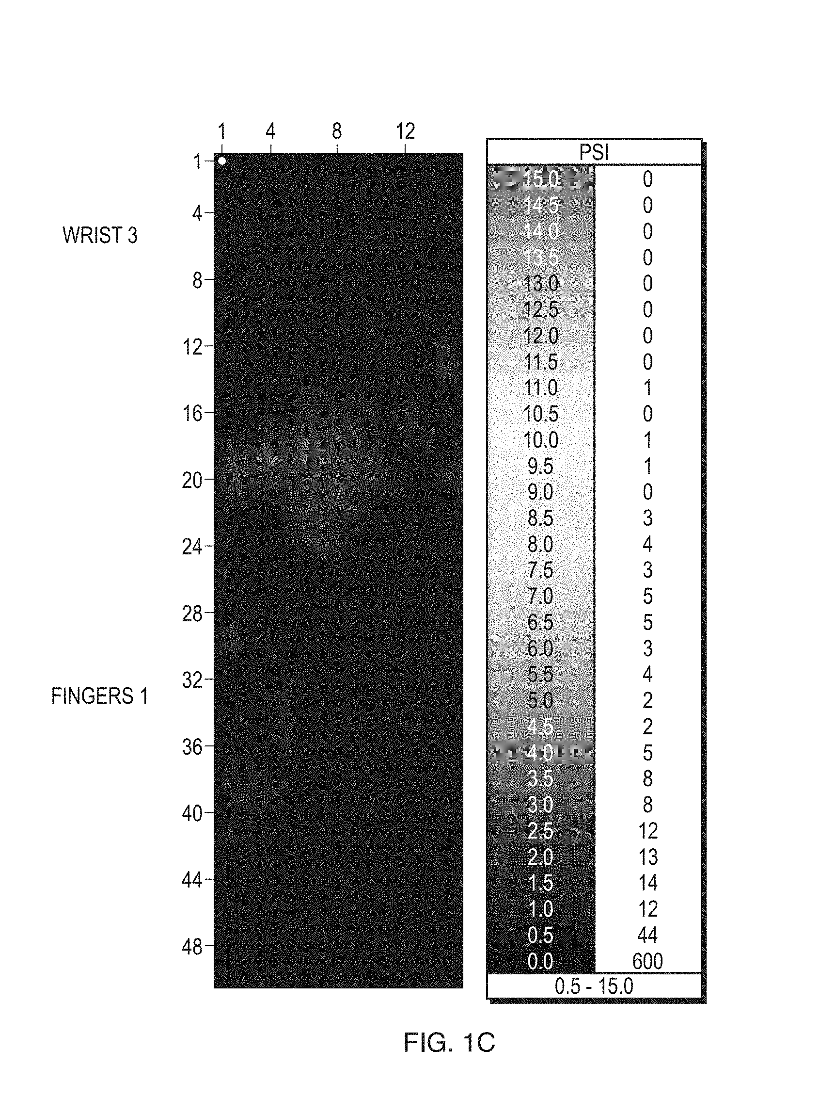
[0014] FIG. 1C shows the pressure distribution across the hand and wrist under a typical traction load;
[0015] FIG. 2 is a cut-away view of an exemplary mitten portion of the hand wrap of this disclosure;
[0016] FIG. 3A illustrates an exemplary palm support plate of the hand wrap of this disclosure;
[0017] FIG. 3B illustrates an exemplary wrist support of the hand wrap of this disclosure;
[0018] FIG. 4 shows an exemplary overwrapping of the hand wrap of this disclosure;
[0019] FIG. 5A is a schematic illustration of a limb positioning device for applying traction to the hand wrap of this disclosure; and
[0020] FIGS. 5B-E show an exemplary sterile connector and drape for connecting the hand wrap of this disclosure to the limb positioning device of FIG. 5A.
DETAILED DESCRIPTION
[0021] In the description that follows, like components have been given the same reference numerals, regardless of whether they are shown in different examples. To illustrate example(s) in a clear and concise manner, the drawings may not necessarily be to scale and certain features may be shown in somewhat schematic form. Features that are described and/or illustrated with respect to one example may be used in the same way or in a similar way in one or more other examples and/or in combination with or instead of the features of the other examples.
[0022] As used in the specification and claims, for the purposes of describing and defining the invention, the terms "about" and "substantially" are used represent the inherent degree of uncertainty that may be attributed to any quantitative comparison, value, measurement, or other representation. The terms "about" and "substantially" are also used herein to represent the degree by which a quantitative representation may vary from a stated reference without resulting in a change in the basic function of the subject matter at issue. "Comprise," "include," and/or plural forms of each are open ended and include the listed parts and can include additional parts that are not listed. "And/or" is open-ended and includes one or more of the listed parts and combinations of the listed parts.
[0023] FIGS. 1A and 1B illustrate a prior art surgical hand wrap for attaching a patient's arm 2 and hand 4 to a limb positioning device. Typically, before being secured to the limb positioning device, the patient's hand 4 is attached to a handle or bar 6 and secured into a balled fist, as shown in FIG. 1A. Portions of the arm 2 and the hand 4 are draped or covered in a flexible sleeve 8 and secured in place with straps 5. The entire arm 2 is then wrapped with an elasticated bandage 9, as shown in FIG. 1B. The distal end of the bandage 9 is attached to weights via a rope 7 and a series of pulleys on a limb positioning device, such as the limb positioning device illustrated in FIG. 5A. However, this method of securing the hand 4 can lead to numbness in the patient's hand 4 and fingers 1. FIG. 1C shows the high-contact pressure points across the fingers 1 and wrist 3 of the patient under traction load when the hand 4 and arm 2 are attached to the limb positioning device in this manner. Such high-contact pressure points can lead to the numbing effect of the hand 4 and fingers 1.
[0024] Turning now to FIG. 2, a cut-away view of an exemplary surgical hand wrap 10 of this disclosure is shown. As illustrated in FIG. 2, the hand wrap 10 may include a flexible mitten portion 12 having an interior side 14 and an exterior side 16. The mitten portion 12 may be made of a variety of flexible plastic or fabric materials, including, but not limited to, urethane foam and polyester fabric. The mitten portion 12 is configured to enclose at least the hand 4 of a patient in an open position, which advantageously reduces the possibility of numbness developing in the patient's hand 4 and fingers 1 during the surgical procedure. In examples, the interior side 14 of the mitten portion 12 adjacent to the palm of the hand 4 comprises an anti-slip material, such as styrene-butadiene rubber (SBR) bonded foam, rubber, or urethane foam. The hand 4 is secured within the mitten portion 12 by at least one closeable strap 20 (such as Velcro.RTM. straps) wrapped around the exterior side 16 of the mitten portion 12. For example, the straps 20 may be wrapped around the mitten portion 12 adjacent the patient's hand 4 and wrist 3. The straps 20 may be secured to the mitten portion 12 at one end or they may be free floating. The straps 20 are used to hold the hand 4 and wrist 3 firmly but not tightly within the mitten portion 12 to prevent any substantial movement of the hand 4 and wrist 3 in either rotation or translation.
[0025] Once the hand 4 is secured within the mitten portion 12, the mitten portion 12 may be attached to an anatomically-shaped plate 22, shown in more detail to FIG. 3A. The plate 22 is configured to support the palm of the hand 4 in the open position. In examples, the plate 22 is comprised of a material which has adequate strength and resistance to sterilization using radiation, such as polycarbonate plate. Notably, the plate 22 can take a variety of sizes and shapes as long as it is configured to support the palm in the open position. In the example of FIG. 3A, the plate has a distal portion 23 configured to attach to a limb positioning device. The plate 22 also includes a center portion 24 which is curve-shaped to support the fingers 1 of the hand 4. Finally, the plate 22 includes a proximal portion 25. The proximal portion 25 may include one or more slots 27 through which the straps 20 may be passed to attach the mitten portion 12 to the plate 22 near the patient's wrist 3. In order to reduce slippage and pressure on the ulnar and radial sides of the wrist, which may lead to nerve injury, the hand wrap 10 may be provided with additional padding 29 within the mitten portion 12 for wrapping around the wrist of the patient, as shown in FIG. 3B. In examples, the padding may be a foam padding, and may be secured to the wrist by a strap 31 wrapped around the wrist. A thickness of the padding 29 is selected to be greater than a thickness of the mitten portion 12. Finally, the hand wrap 10 is overwrapped with an elastic bandage 26, as shown in FIG. 4. It is also contemplated by this disclosure that the hand 4 of the patient could be secured to the plate 22 without the use of the mitten portion 12.
[0026] Turning now to FIG. 5A, a limb positioning device 28 is illustrated, the component parts of which are described in more detail below. In FIG. 5A, a patient 30 is shown lying on a standard operating table 32 and prepared for a surgical operation. The forearm of the arm 2 to be operated upon is encased within the hand wrap 10 of this disclosure. The distal end of the hand wrap 10 is then attached to weights 40 via a series of ropes 42 and pulleys 44 on the limb positioning device 28. Advantageously, when traction is applied to the hand wrap 10 by the limb positioning device 28, the shape of the plate 22, the construction of the mitten portion 12, and the straps 20 combine to allow low-contact pressure across the hand 4 and the wrist 3 of the patient 30. In examples, various components of the limb positioning device may contain telescoping or other features for lengthening or shortening the components, and/or height adjusting features for raising or lowering the components.
[0027] As shown in FIG. 5B, once the hand wrap 10 has been secured to the plate 22. The distal portion 23 of the plate 22 is connected to the limb positioning device 28 by means of an exemplary sterile connector 34 of this disclosure, shown in more detail in FIG. 5C. The sterile connector 34 may be made of polymers, metals or other suitable materials and is intended to be disposed of after use. As shown in FIG. 5C, the sterile connector 34 has a T-fitting 36 at its distal end and a keyed shaft 38 at its proximal end. The T-fitting 36 is configured to couple to the distal portion 23 of the plate 22 of the limb positioning device 28. The shaft 38 is configured to mate with a receiver 40 permanently attached to the distal end of the limb positioning device 28, as shown in FIG. 5D.
[0028] Also shown in FIG. 5D, attached to the sterile connector 34 is a flexible dam portion 42 of a sterile drape or covering 44. In examples, the proximal end of the covering 44 is open such that the covering 44 is configured to cover at least a portion of the limb positioning device 28. The covering 44 may be fabricated from a variety of different materials that may be sterilized and which are preferably latex-fee, such as polyethylene plastics. In examples, the covering 44 may be formed from a pre-formed tubular sheet of the plastic material or from plural sheets of plastic material formed into a tube with longitudinal seams. It will be appreciated that the dimensions and configuration of the covering 44 will vary depending upon the type and structure of the limb positioning device or other equipment that the covering 44 is designed to cover. The dam portion 42 is attached to the covering 44 in an appropriate manner such as sonic welding or adhesives. The dam portion 42 may be fabricated from any number of flexible, non-slip materials, such as rubber. In examples, the sterile connector 34 is held in the dam portion 42 in an interference fit due to the elastic nature of the rubber. As shown in FIG. 5E, in use, the covering 44 may be folded in telescopic fashion to allow for visualization of the shaft 38 of the sterile connector 34 for easing insertion into the receiver 40 of the limb positioning device 28.
[0029] In other examples, not shown, the shape of the T-fitting 36 and the shaft 38 could be changed to suit different applications. For example, the shaft 38 could be reconfigured to make it symmetrical to the T-fitting 36. In other examples, the sterile connector 34 could be clamped or glued in place, or held by a fastening ring. In addition, the dam portion 42 could be eliminated, allowing the covering 44 to be directly attached to the sterile connector 34. Advantageously, the sterile connector 34 of this disclosure allows for a sterile operator to attach the sterile hand wrap 10 to the limb positioning device 28 in the sterile field without the need for a non-sterile operator. This in turn allows for faster turnover between procedures by eliminating the need for re-usable (i.e., autoclaveabie) interfaces.
[0030] While this disclosure has been particularly shown and described with references to preferred embodiments thereof, it will be understood by those skilled in the art that various changes in form and details may be made therein without departing from the spirit and scope of the present application as defined by the appended claims. Such variations are intended to be covered by the scope of this present application. As such, the foregoing description of embodiments of the present application is not intended to be limiting, the full scope rather being conveyed by the appended claims.
* * * * *
D00000
D00001
D00002
D00003
D00004
D00005
D00006
D00007
XML
uspto.report is an independent third-party trademark research tool that is not affiliated, endorsed, or sponsored by the United States Patent and Trademark Office (USPTO) or any other governmental organization. The information provided by uspto.report is based on publicly available data at the time of writing and is intended for informational purposes only.
While we strive to provide accurate and up-to-date information, we do not guarantee the accuracy, completeness, reliability, or suitability of the information displayed on this site. The use of this site is at your own risk. Any reliance you place on such information is therefore strictly at your own risk.
All official trademark data, including owner information, should be verified by visiting the official USPTO website at www.uspto.gov. This site is not intended to replace professional legal advice and should not be used as a substitute for consulting with a legal professional who is knowledgeable about trademark law.