An Electrosurgical Illuminating Instrument
Blus; Theodore C. ; et al.
U.S. patent application number 16/090954 was filed with the patent office on 2019-05-09 for an electrosurgical illuminating instrument. The applicant listed for this patent is Kester J. BATCHELOR, Theodore C. BLUS, Gyrus ACMi, Inc., d.b.a. Olympus Surgical Technolo, Jyue Boon LIM. Invention is credited to Kester J. Batchelor, Theodore C. Blus, Jyue Boon Lim.
| Application Number | 20190133710 16/090954 |
| Document ID | / |
| Family ID | 55754457 |
| Filed Date | 2019-05-09 |

| United States Patent Application | 20190133710 |
| Kind Code | A1 |
| Blus; Theodore C. ; et al. | May 9, 2019 |
AN ELECTROSURGICAL ILLUMINATING INSTRUMENT
Abstract
An electrosurgical instrument includes a light source, a first conductor, a second conductor, an insulation material positioned between the first conductor and the second conductor, and a light pipe that carries light from the light source to the insulation material.
| Inventors: | Blus; Theodore C.; (Shoreview, MN) ; Lim; Jyue Boon; (New Brighton, MN) ; Batchelor; Kester J.; (Mound, MN) | ||||||||||
| Applicant: |
|
||||||||||
|---|---|---|---|---|---|---|---|---|---|---|---|
| Family ID: | 55754457 | ||||||||||
| Appl. No.: | 16/090954 | ||||||||||
| Filed: | April 4, 2016 | ||||||||||
| PCT Filed: | April 4, 2016 | ||||||||||
| PCT NO: | PCT/US2016/025849 | ||||||||||
| 371 Date: | October 3, 2018 |
| Current U.S. Class: | 1/1 |
| Current CPC Class: | A61B 90/30 20160201; A61B 18/148 20130101; A61B 2018/00589 20130101; A61B 2090/0807 20160201; A61B 2018/00898 20130101; A61B 90/08 20160201; A61B 2018/00982 20130101; A61B 2090/308 20160201; A61B 18/14 20130101; A61B 2090/306 20160201; A61B 2018/00595 20130101; A61B 18/1482 20130101 |
| International Class: | A61B 90/30 20060101 A61B090/30; A61B 90/00 20060101 A61B090/00; A61B 18/14 20060101 A61B018/14 |
Claims
1.-35. (canceled)
36. An electrosurgical instrument comprising: a light pipe, configured to transmit light between a proximal end configured to receive light from a light source and a distal end configured to emit light; and an insulation material disposed between a first conductor and a second conductor and configured to transmit light from an incident surface in optical communication with the distal end of the light pipe to an emitting surface-configured to emit light.
37. The electrosurgical instrument of claim 36 wherein the insulation material is translucent.
38. The electrosurgical instrument of claim 36 further comprising: a handpiece comprising the light source; and an extension comprising a proximal end connected to the handpiece and a distal end positioned at the distal end of the light pipe.
39. The electrosurgical instrument of claim 38 wherein the insulation material is configured to illuminate a surgical site with light transmitted via the light pipe from the light source.
40. The electrosurgical instrument of claim 38 wherein the emitting surface is located at the distal ends of the first and second conductors, the lateral sides of the first and second conductors, or both the distal ends and the lateral sides of the first and second conductors.
41. The electrosurgical instrument of claim 38 wherein the insulation material is configured to display an instrument state of the electrosurgical instrument.
42. The electrosurgical instrument of claim 41 wherein the emitting surface comprises a diffuser surface to diffuse light.
43. An electrosurgical instrument comprising: an insulation material comprising: an incident surface configured to receive light from a light source; an emitting surface configured to emit light and positioned relative to a location selected from a group consisting of: distal ends of a first conductor and a second conductor; and lateral sides of the first conductor and the second conductor.
44. The electrosurgical instrument of claim 43 wherein the emitting surface is located at the distal ends of the first and second conductors.
45. The electrosurgical instrument of claim 43 further comprising: a handpiece comprising the light source; and an extension comprising a proximal end connected to the handpiece, the first conductor and the second conductor being positioned at the distal end of the extension.
46. The electrosurgical instrument of claim 43 wherein the emitting surface is configured to display an instrument state of the electrosurgical instrument and the emitting surface comprises a diffuser surface.
47. A surgical instrument comprising: a handpiece; a surgical end; and a light pipe configured to selectively transmit light between a proximal end configured to receive light from a light source positioned in the handpiece and a distal end configured to emit light.
48. The surgical instrument of claim 47 wherein, in a first illumination state, the proximal end of the light pipe is in optical communication with the light source to receive light and transmit the light to the distal end of the light pipe; and wherein, in a second illumination state, the proximal end of the light pipe is not in optical communication with the light source.
49. The surgical instrument of claim 48 wherein in the first illumination state the surgical instrument is configured to transmit light to the surgical end to provide localized illumination of a surgical site and in the second illumination state the surgical instrument is configured to provide wide illumination of the surgical site.
50. The surgical instrument of claim 49 wherein the light pipe comprises an insulation material disposed between a first conductor and a second conductor comprising: an incident surface configured to receive light from a light source; and an emitting surface configured to emit light for localized illumination of the surgical site when the surgical instrument is in the first illumination state and positioned relative to a location selected from a group consisting of: distal ends of the first conductor and the second conductor, and the lateral sides of the first conductor and the second conductor.
51. The surgical instrument of claim 50 further comprising: an extension comprising a proximal end connected to the handpiece and a distal end positioned at the distal end of the extension.
52. The surgical instrument of claim 49 further comprising an insulation material disposed between a first conductor and a second conductor and configured to transmit light from an incident surface in optical communication with the distal end of the light pipe to an emitting surface configured to emit light.
53. The surgical instrument of claim 52 further comprising an extension comprising a proximal end connected to the handpiece and a distal end positioned at the distal end of the extension.
54. The surgical instrument of claim 48 further comprising an insulation material disposed between a first electrode and a second electrode and configured to transmit light from an incident surface in optical communication with the distal end of the light pipe to an emitting surface configured to emit light, wherein in the first illumination state the insulation material is configured to display an instrument state of the surgical instrument, and in the second illumination state the surgical instrument is configured to provide wide illumination of the surgical site.
55. The surgical instrument of claim 54 wherein the emitting surface comprises a diffuser surface to diffuse light.
Description
FIELD
[0001] The present disclosure relates to an electrosurgical instrument. More specifically, the present disclosure relates to an electrosurgical illuminating instrument.
BACKGROUND
[0002] The statements in this section merely provide background information related to the present disclosure and may or may not constitute prior art.
[0003] Electrosurgical illuminating instruments have become widely employed by medical professionals in recent years. A number of electrosurgical illuminating instruments have been developed whereby an active electrode is attached to an insulated handle and a high frequency current is applied thereto. Accordingly, electrosurgical illuminating instruments are used by medical professionals in various types of surgical procedures. A common surgical procedure involves cauterizing a patient's tissue. Typically, cauterizing is employed to sterilize and cut tissue as well as to kill certain tissue that has been infected with disease such as cancer and the like. To accurately perform the surgical procedure, the medical professional needs to be able to illuminate and view the local tissue area to be cauterized. Thus, it is imperative that adequate lighting be provided to the affected regions during the surgical procedure. Overhead surgery room lighting, however, is rarely sufficient. Accordingly, various types of supplemental lighting equipment have been developed that suits different medical illumination requirements, for example, the incorporation of a lighting source to a surgical instrument.
[0004] Most existing surgical light sources involve fiber optic cable or bundles that are permanently attached to a particular surgical instrument with one end of the fiber optic cable or bundle connected to a source of illumination. These types of surgical instrument lights are disclosed in U.S. Pat. Nos. 6,585,727; 5,376,087; and 4,688,569. Such instruments, however, are cumbersome to manufacture and to use in a surgery room setting.
[0005] Accordingly, there is need for a surgical instrument that incorporates an effective light source.
SUMMARY
[0006] The present invention provides an electrosurgical illuminating instrument.
[0007] Accordingly, pursuant to one aspect of the present invention, an electrosurgical instrument includes a light source, a first conductor, a second conductor, an insulation material positioned between the first conductor and the second conductor, and a light pipe that carries light from the light source to the insulation material.
[0008] Accordingly, pursuant to another aspect of the present invention, an electrosurgical instrument includes a light source, a first conductor, a second conductor, and an insulation material positioned between the first conductor and the second conductor, the insulation material being a light pipe that carries light from the light source.
[0009] The above aspects of the present invention can be further characterized by one or any combination of the features described herein, such as: the insulation material is translucent, transparent or both translucent and transparent; a portion of the insulation material is opaque; a handpiece, the light source being positioned in the handpiece; an extension with a proximal end and a distal end, the proximal end of the extension being connected to the handpiece, the first conductor and the second conductor being positioned at the distal end of the extension; the first conductor, the second conductor and the insulation material are configured to illuminate a surgical site; the insulation material has an exterior surface that transmits the incident light; the surface that transmits the incident light is located at the distal ends of the first and second conductors, the lateral sides of the first and second conductors, or both the distal ends and the lateral sides of the first and second conductors; the first conductor, the second conductor and the insulation material are configured to display an instrument state of the electrosurgical instrument; the electrosurgical instrument is capable of delivering a therapy current between the first conductor and the second conductor; the insulation material has a frosted surface to diffuse the light; at least of a portion of the insulation material is an indicator that displays an instrument state of the electrosurgical instrument; the insulation material is made from a material selected from a group consisting of ceramic, silicon rubber, glass, and titanium dioxide; the light source is an LED; and the first conductor is a first electrode and the second conductor is a second electrode.
[0010] Accordingly, pursuant to another aspect of the present invention, an electrosurgical instrument includes a handpiece, a surgical end, a light source positioned in the handpiece, and a light pipe with a proximal end and distal end. The proximal end of the light pipe selectively engages optically with the light source to transmit light to the distal end of the light pipe such that light is transmitted to the surgical end which converts from wide illumination to tip illumination of a surgical site.
[0011] This aspect of the present invention can be further characterized by one or any combination of the features described herein, such as: the surgical end includes a first electrode, a second electrode, and an insulation layer positioned between the first electrode and the second electrode; the light pipe transmits light from the light source to the insulation layer; the insulation material is translucent, transparent or both translucent and transparent; a portion of the insulation material is opaque; the first conductor, the second conductor, and the insulation material are configured to display an instrument state of the electrosurgical instrument; the insulation material has a frosted surface to diffuse the light; the insulation material is made from a material selected from a group consisting of ceramic, silicon rubber, glass, and titanium dioxide; the light source is an LED.
[0012] Accordingly, pursuant to yet another aspect of the present invention, an electrosurgical instrument includes a handpiece, a light source positioned in the handpiece, a surgical end with a first electrode, a second electrode, and an insulation material positioned between the first electrode and the second electrode; and a light pipe that carries light from the light source to the insulation material.
[0013] This aspect of the present invention can be further characterized by one or any combination of the features described herein, such as: the light pipe has a proximal end and distal end, the proximal end of the light pipe selectively engaging optically with the light source to transmit light to the distal end of the light pipe such that light is transmitted to the surgical end which converts from wide illumination to tip illumination of a surgical site; the insulation material is translucent, transparent or both translucent and transparent; a portion of the insulation material is opaque; an extension with a proximal end and a distal end, the proximal end of the extension being connected to the handpiece, the first electrode and the second electrode being positioned at the distal end of the extension; the first electrode, the second electrode and the insulation material are configured to illuminate a surgical site; the first electrode, the second electrode and the insulation material are configured to display an instrument state of the electrosurgical instrument; the insulation material has a frosted surface to diffuse the light; the insulation material is made from a material selected from a group consisting of ceramic, silicon rubber, glass, and titanium dioxide; and the light source is an LED.
[0014] Further features, advantages, and areas of applicability will become apparent from the description provided herein. It should be understood that the description and specific examples are intended for purposes of illustration only and are not intended to limit the scope of the present disclosure.
DRAWINGS
[0015] The drawings described herein are for illustration purposes only and are not intended to limit the scope of the present disclosure in any way. The components in the figures are not necessarily to scale, emphasis instead being placed upon illustrating the principles of the invention. In the drawings:
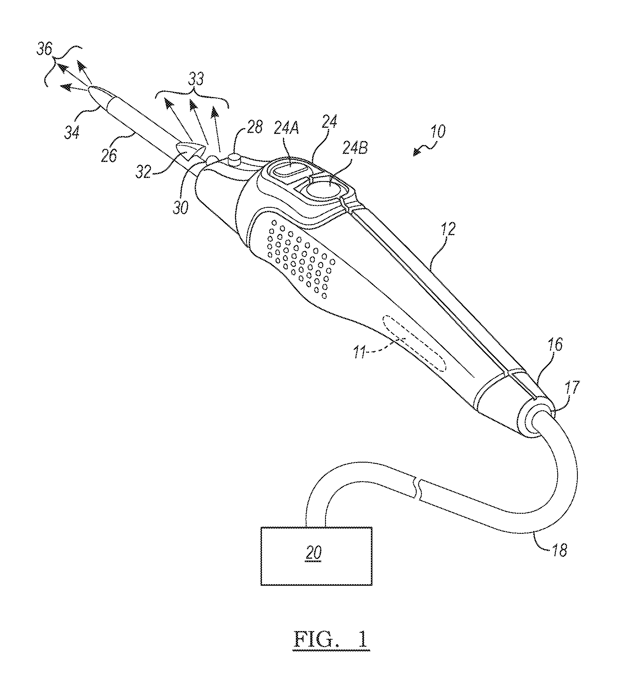
[0016] FIG. 1 is a perspective view of an electrosurgical illuminating instrument in accordance with the principles of the present invention;
[0017] FIG. 2 is a side view of the electrosurgical illuminating instrument; and
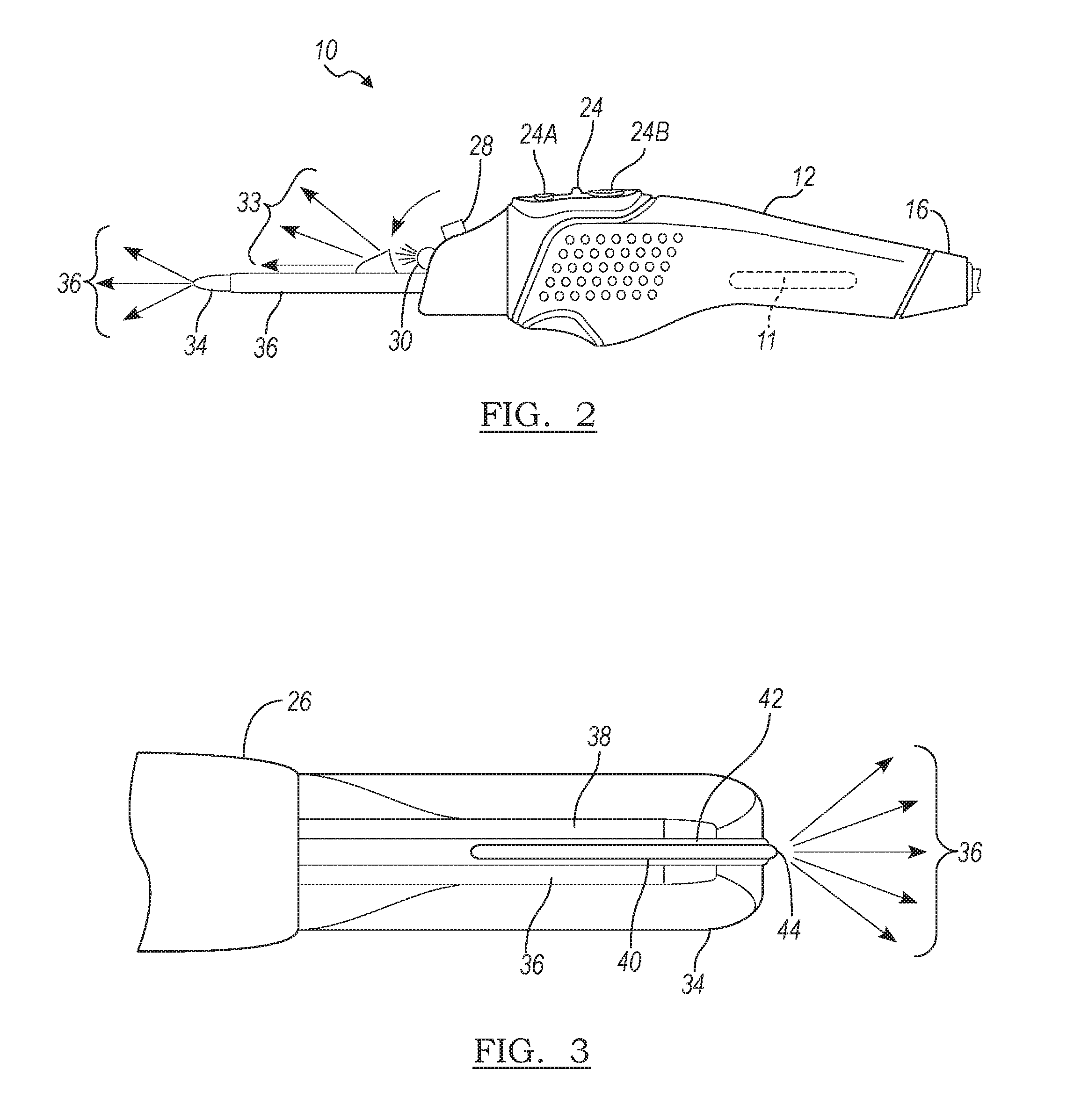
[0018] FIG. 3 is a close-up view of a distal end of the electrosurgical illuminating instrument.
DETAILED DESCRIPTION
[0019] The following description is merely exemplary in nature and is not intended to limit the present disclosure, application, or uses.
[0020] With reference to FIG. 1, an electrosurgical illuminating instrument embodying the principles of the present invention is illustrated therein and designated at 10. The electrosurgical illuminating instrument 10 is self-powered by one or more batteries 11 or receives electrical energy from an electrical energy source 20, or is powered by both the batteries 11 and the electrical energy source 20. The proximal end 16 of the electrosurgical illuminating instrument 10 includes a connector 17 that connects the electrosurgical illuminating instrument 10 to the energy source 20 with a lead 18.
[0021] The electrosurgical illuminating instrument 10 includes a main body 12, a light pipe 26, a light source 30, and a directing light cover 32. The light source 30 can be any suitable light source, such as, for example, one or more LEDs. If more than one LED is employed, the LEDs can be multicolored. In various arrangements, the light pipe 26 is a bundle of fiber optics.
[0022] The electrosurgical illuminating instrument 10 further includes a switch 24 that turns the electrosurgical illuminating instrument 10 on and off. For example, in a particular arrangement the switch includes a first switch 24a that turns the light source 30 on and off and a second switch 24b that activates the energy source 20 to deliver RF electrical energy to a distal end 34 of the electrosurgical illuminating instrument 10. In particular arrangements, the one or more batteries 11 provides electrical energy to the light source 30 and the energy source 20 provides RF electrical energy to the distal end 34 to treat tissue in proximity of the distal end 34.
[0023] The electrosurgical illuminating instrument 10 also includes a button 28 that toggles the electrosurgical illuminating instrument 10 from wide illumination of the surgical site to narrow illumination of the site from the distal end 34 of the electrosurgical illuminating instrument 10. More specifically, when the button 28 is in the wide illumination position, the light source 30 is uncovered by the light cover 32 to provide wide illumination of the surgical site as indicated by the arrows 33, and when the button 28 is in the narrow illumination position, the light source 30 rotates downward towards the light cover 32 such that the light cover 32 directs light from the light source 30 to the distal end 34 through the light pipe 26 to provide localized illumination (as indicated by the arrows 36) at the surgical site. Accordingly, a medical professional is able to illuminate and view local tissue to be treated to accurately perform a surgical procedure with the electrosurgical illuminating instrument 10. Further, the electrosurgical illuminating instrument 10 meets the strict waterproofing and sanitizing requirements of a surgery room.
[0024] Referring now to FIG. 3, the distal end 34 of the electrosurgical illuminating instrument 10 is shown in greater detail. As described above the distal end 34 receives light from the light pipe 26. Hence, the distal end 34 can be a second light pipe that optically communicates with the light pipe 26 or an extension of the light pipe 26. The distal end 34 of the electrosurgical illuminating instrument 10 includes a first conductor 36, a second conductor 38, and an insulation material 40, 42 positioned between the first conductor 36 and 38. In some arrangements, the insulation material 40, 42 can be a single piece of insulation material or in other arrangements the insulation material 40, 42 can include a portion separated by a spacer 44.
[0025] In various arrangements, the insulation material 40, 42 is translucent, whereas in other arrangements the insulation material 40, 42 is transparent. In particular arrangements, the insulation material includes a transparent portion and a translucent portion. Some portion or portions of the insulation material 40, 42 may be opaque so that light is not transmitted from the opaque portions. All or a portion of the insulation material 40, 42 may be frosted to diffuse the light.
[0026] The insulation material can be made from any suitable material, such as, for example, ceramic, silicone rubber, glass, or titanium dioxide, or any combination of these materials.
[0027] The first conductor 36 and the second conductor 38 can operate as bipolar electrodes of the electrosurgical illumination instrument 10. In such arrangements, the first and second conductors receive RF electrical energy from, for example, the energy source 20 such that a voltage potential is generated between the first conductor 36 and the second conductor 38, which causes a current to pass from one conductor to the other through tissue being treated by the electrosurgical illuminating instrument 10. This current heats the tissue to coagulate or cauterize the tissue depending on the amount of RF energy supplied to the conductors 36 and 38.
[0028] In some arrangements, a portion of the insulation material 40, 42 acts as an indicator to provide visual feedback to the medical profession about the instrument state of the electrosurgical illuminating instrument 10. For example, the color of the light can change from one color to another color after a particular procedure (such as coagulation or cauterization of tissue) is completed. In particular arrangements, the light source 30 is configured to blink, for example, at different frequencies, to indicate various instrument states of the electrosurgical illuminating instrument 10.
[0029] The description of the invention is merely exemplary in nature and variations that do not depart from the gist of the invention are intended to be within the scope of the invention. Such variations are not to be regarded as a departure from the spirit and scope of the invention.
* * * * *
D00000
D00001
D00002
XML
uspto.report is an independent third-party trademark research tool that is not affiliated, endorsed, or sponsored by the United States Patent and Trademark Office (USPTO) or any other governmental organization. The information provided by uspto.report is based on publicly available data at the time of writing and is intended for informational purposes only.
While we strive to provide accurate and up-to-date information, we do not guarantee the accuracy, completeness, reliability, or suitability of the information displayed on this site. The use of this site is at your own risk. Any reliance you place on such information is therefore strictly at your own risk.
All official trademark data, including owner information, should be verified by visiting the official USPTO website at www.uspto.gov. This site is not intended to replace professional legal advice and should not be used as a substitute for consulting with a legal professional who is knowledgeable about trademark law.