Modular Physiological Sensors
Al-Ali; Ammar ; et al.
U.S. patent application number 16/182388 was filed with the patent office on 2019-05-09 for modular physiological sensors. The applicant listed for this patent is MASIMO CORPORATION. Invention is credited to Ammar Al-Ali, Kevin Forrest.
| Application Number | 20190133525 16/182388 |
| Document ID | / |
| Family ID | 54337897 |
| Filed Date | 2019-05-09 |


| United States Patent Application | 20190133525 |
| Kind Code | A1 |
| Al-Ali; Ammar ; et al. | May 9, 2019 |
MODULAR PHYSIOLOGICAL SENSORS
Abstract
Modular physiological sensors that are physically and/or electrically configured to share a measurement site for the comfort of the patient and/or to ensure proper operation of the sensors without interference from the other sensors. The modular aspect is realized by providing outer housing shapes that generally conform to other physiological sensors; mounting areas for attachment of one sensor to another sensor; providing release liners on the overlapping sensor attachment areas; and/or providing notches, tabs or other mechanical features that provide for the proper placement and interaction of the sensors.
| Inventors: | Al-Ali; Ammar; (San Juan Capistrano, CA) ; Forrest; Kevin; (Rancho Santa Margarita, CA) | ||||||||||
| Applicant: |
|
||||||||||
|---|---|---|---|---|---|---|---|---|---|---|---|
| Family ID: | 54337897 | ||||||||||
| Appl. No.: | 16/182388 | ||||||||||
| Filed: | November 6, 2018 |
Related U.S. Patent Documents
| Application Number | Filing Date | Patent Number | ||
|---|---|---|---|---|
| 14876307 | Oct 6, 2015 | 10154815 | ||
| 16182388 | ||||
| 62061132 | Oct 7, 2014 | |||
| Current U.S. Class: | 1/1 |
| Current CPC Class: | A61B 5/14553 20130101; A61B 2562/06 20130101; A61B 5/1455 20130101; A61B 5/0478 20130101; A61B 2562/04 20130101; A61B 5/684 20130101; A61B 5/6833 20130101; A61B 5/0476 20130101; A61B 2560/0443 20130101; A61B 5/6814 20130101 |
| International Class: | A61B 5/00 20060101 A61B005/00; A61B 5/1455 20060101 A61B005/1455; A61B 5/0478 20060101 A61B005/0478; A61B 5/0476 20060101 A61B005/0476 |
Claims
1-22. (canceled)
23. A modular physiological sensor comprising: an electroencephalogram (EEG) sensor comprising a stem, a left branch, and a right branch, the left branch and the right branch extending generally perpendicularly from the stem so as to form a branch intersection, wherein the branch intersection includes a left corner defined by an intersection of the left branch and the stem of the EEG sensor and a right corner defined by an intersection of the right branch and the stem of the EEG sensor; a plurality of EEG electrodes disposed along the left branch and the right branch; a ground electrode and a reference electrode disposed proximate the branch intersection; a first mounting zone extending along an edge of the left corner of the branch intersection and configured for removable attachment of a first portion of a first regional oximetry (rO2) sensor; and a second mounting zone extending along an edge of the right corner of the branch intersection and configured for removable attachment of a first portion of a second rO2 sensor.
24. The modular physiological sensor according to claim 23, wherein, when the first portion of the first rO2 sensor is attached to the first mounting zone along the edge of the left corner of the branch intersection, a second portion of the first rO2 sensor contacts tissue of a wearer of the modular physiological sensor, the tissue being proximate to the first mounting zone, and wherein, when the first portion of the second rO2 sensor is attached to the second mounting zone along the edge of the right corner of the branch intersection, a second portion of the second rO2 sensor contacts tissue of the wearer of the modular physiological sensor, the tissue being proximate to the second mounting zone, and wherein the first and second rO2 sensors each comprise a pair of light emitting and light detecting elements located in the second portions of the first and second rO2 sensors.
25. The modular physiological sensor according to claim 24, wherein a skin-side surface of the EEG sensor is colored black so as to prevent the EEG sensor from reflecting light emitted from the first and second rO2 sensors.
26. The modular physiological sensor according to claim 23, wherein the first mounting zone comprises a first positioning line configured to aid attachment of the first portion of the first rO2 sensor, and wherein the second mounting zone comprises a second positioning line configured to aid attachment of the first portion of the second rO2 sensor.
27. The modular physiological sensor according to claim 23, wherein the edge of the left corner of the branch intersection has a first curvature and the first portion of the first rO2 sensor has an edge with a second curvature equal to the first curvature such that, when the first portion of the first rO2 sensor is attached to the first mounting zone, the edge of the first portion of the first rO2 sensor aligns with the edge of the left corner of the branch intersection.
28. The modular physiological sensor according to claim 23, wherein: the first rO2 sensor has a plurality of notches along a perimeter of the first portion of the first rO2 sensor and the second rO2 sensor has a plurality of notches along a perimeter of the first portion of the second rO2 sensor; the first mounting zone includes a plurality of notch markings configured to align with the plurality of notches of the first rO2 sensor so as to aid attachment of the first portion of the first rO2 sensor on the first mounting zone; and the second mounting zone includes a plurality of notch markings configured to align with the plurality of notches of the second rO2 sensor so as to aid attachment of the first portion of the second rO2 sensor on the second mounting zone.
29. The modular physiological sensor according to claim 23, wherein each of the first portions of the first and second rO2 sensors comprises a curved perimeter, and wherein the first and second mounting zones are shaped to accommodate the curved perimeters of each of the first portions of the first and second rO2 sensors.
30. A method of attaching a modular physiological sensor to a patient, the method comprising: attaching an electroencephalogram (EEG) sensor on a forehead tissue site, the EEG sensor comprising a stem, a left branch, and a right branch, wherein the left branch and the right branch extend generally perpendicularly from the stem so as to form a branch intersection, the branch intersection including a left corner defined by the intersection of the left branch and the stem of the EEG sensor and a right corner defined by the intersection of the right branch and the stem of the EEG sensor, the EEG sensor further comprising a first mounting zone extending along an edge of the left corner of the branch intersection; and attaching a first portion of a first regional oximetry sensor to the first mounting zone of the EEG sensor.
31. The method according to claim 30, further comprising attaching a second portion of the first regional oximetry sensor to tissue at the forehead tissue site proximate to the first mounting zone.
32. The method according to claim 31, wherein the EEG sensor further comprises a second mounting zone extending along an edge of the right corner of the branch intersection, and wherein the method further comprises attaching a first portion of a second regional oximetry sensor to the second mounting zone of the EEG sensor and attaching a second portion of the second regional oximetry sensor to tissue at the forehead tissue site proximate to the second mounting zone.
33. The method according to claim 31, wherein the step of attaching the first portion of the first regional oximetry sensor to the first mounting zone of the EEG occurs prior to the step of attaching a second portion of the first regional oximetry sensor to tissue at the forehead tissue site proximate to the first mounting zone.
34. The method according to claim 30, wherein the step of attaching the first portion of the first regional oximetry sensor to the first mounting zone of the EEG occurs after the step of attaching the EEG sensor on the forehead tissue site.
35. The method according to claim 30, wherein the first portion of the first regional oximetry sensor comprises a plurality of notches, and wherein the first mounting zone comprises a plurality of notch markings, the method further comprising aligning the plurality of notches of the first portion of the first regional oximetry sensor with the plurality of notch markings on the first mounting zone.
36. The method according to claim 30, wherein the edge of the left corner of the branch intersection of the EEG sensor is curved, and wherein, when the first portion of the first regional oximetry sensor is attached to the first mounting zone of the EEG sensor, a curved edge of the first portion of the first regional oximetry sensor aligns with the curved edge of the left corner of the branch intersection.
37. A modular physiological sensor comprising: an electrical sensor configured to passively measure an EEG signal, the electrical sensor comprising a generally T shape including a first mounting zone positioned adjacent to an edge of a left corner of a left side of a vertical middle of the T shape and a second mounting zone positioned adjacent to an edge of a right corner of a right side of the vertical middle of the T shape; an optical sensor configured to detect an oxygen saturation, the optical sensor comprising a plurality of notches along a perimeter of the first portion of the optical sensor, wherein each of the plurality of notches extends from the perimeter of the first portion of the optical sensor inwardly toward an interior of the optical sensor; and wherein at least one of the first mounting zone and the second mounting zone includes a plurality of notch markings configured to align with the plurality of notches of the optical sensor when the first portion of the optical sensor is attached to either the first or second mounting zone.
38. The modular physiological sensor according to claim 37, wherein, when the first portion of the optical sensor is attached to either the first mounting zone or the second mounting zone of the electrical sensor, a second portion of the optical sensor is configured to attach to a skin surface, the optical sensor comprising a pair of light emitting and light detecting elements positioned within the second portion of the optical sensor.
39. The modular physiological sensor according to claim 38, wherein a skin-side surface of the electrical sensor is colored black so as to prevent the electrical sensor from reflecting light emitted from the optical sensor.
40. The modular physiological sensor according to claim 37, wherein the perimeter of the first portion of the optical sensor is curved, and wherein the first and second mounting zones are shaped to accommodate the curved perimeter of the first portion of the optical sensor.
41. The modular physiological sensor according to claim 37, wherein at least one of the edge of the left corner of the left side of the vertical middle of the T shape and the right corner of the right side of the vertical middle of the T shape has a first curvature, and wherein the first portion of the optical sensor has an edge with a second curvature equal to the first curvature such that, when the first portion of the optical sensor is attached to the first or second mounting mounting zone, the edge of the first portion of the optical sensor aligns with the edge of the left or right corner of the vertical middle of the T shape.
42. The modular physiological sensor according to claim 37, wherein the optical sensor is egg-shaped.
Description
INCORPORATION BY REFERENCE TO ANY PRIORITY APPLICATIONS
[0001] Any and all applications for which a foreign or domestic priority claim is identified in the Application Data Sheet as filed with the present application are hereby incorporated by reference under 37 CFR 1.57.
[0002] The present application is a continuation of U.S. patent application Ser. No. 14/876,307 filed Oct. 6, 2015, which claims priority benefit under 35 U.S.C. .sctn. 119(e) to U.S. Provisional Patent Application Ser. No. 62/061,132 filed Oct. 7, 2014, titled Regional Oximetry-EEG Sensor. The above-cited provisional patent application is hereby incorporated in its entirety by reference herein.
FIELD OF THE DISCLOSURE
[0003] The present disclosure relates to physiological sensors. More specifically, the present disclosure relates to configurations for modular physiological sensors.
BACKGROUND
[0004] Pulse oximetry is a widely accepted noninvasive procedure for measuring the oxygen saturation level of arterial blood, an indicator of a person's oxygen supply. A typical pulse oximetry system utilizes an optical sensor attached to a fingertip to measure the relative volume of oxygenated hemoglobin in pulsatile arterial blood flowing within the fingertip. Oxygen saturation (SpO2), pulse rate and a plethysmograph waveform, which is a visualization of pulsatile blood flow over time, are displayed on a monitor accordingly.
[0005] Conventional pulse oximetry assumes that arterial blood is the only pulsatile blood flow in the measurement site. During patient motion, venous blood also moves, which causes errors in conventional pulse oximetry. Advanced pulse oximetry processes the venous blood signal so as to report true arterial oxygen saturation and pulse rate under conditions of patient movement. Advanced pulse oximetry also functions under conditions of low perfusion (small signal amplitude), intense ambient light (artificial or sunlight) and electrosurgical instrument interference, which are scenarios where conventional pulse oximetry tends to fail.
[0006] Advanced pulse oximetry is described in at least U.S. Pat. Nos. 6,770,028; 6,658,276; 6,157,850; 6,002,952; 5,769,785 and 5,758,644, which are assigned to Masimo Corporation ("Masimo") of Irvine, Calif. and are incorporated in their entireties by reference herein. Corresponding low noise optical sensors are disclosed in at least U.S. Pat. Nos. 6,985,764; 6,813,511; 6,792,300; 6,256,523; 6,088,607; 5,782,757 and 5,638,818, which are also assigned to Masimo and are also incorporated in their entireties by reference herein. Advanced pulse oximetry systems including Masimo SET.RTM. low noise optical sensors and read through motion pulse oximetry monitors for measuring SpO2, pulse rate (PR) and perfusion index (PI) are available from Masimo. Optical sensors include any of Masimo LNOP.RTM., LNCS.RTM., SofTouch.TM. and Blue.TM. adhesive or reusable sensors. Pulse oximetry monitors include any of Masimo Rad 8.RTM., Rad 5.RTM., Rad.RTM.-5v or SatShare.RTM. monitors.
[0007] Advanced blood parameter measurement systems are described in at least U.S. Pat. No. 7,647,083, filed Mar. 1, 2006, titled Multiple Wavelength Sensor Equalization; U.S. Pat. No. 7,729,733, filed Mar. 1, 2006, titled Configurable Physiological Measurement System; U.S. Pat. Pub. No. 2006/0211925, filed Mar. 1, 2006, titled Physiological Parameter Confidence Measure and U.S. Pat. Pub. No. 2006/0238358, filed Mar. 1, 2006, titled Noninvasive Multi-Parameter Patient Monitor, all assigned to Cercacor Laboratories, Inc., Irvine, Calif. (Cercacor) and all incorporated in their entireties by reference herein. Advanced blood parameter measurement systems include Masimo Rainbow.RTM. SET, which provides measurements in addition to SpO2, such as total hemoglobin (SpHbTM), oxygen content (SpOCTM), methemoglobin (SpMet.RTM.), carboxyhemoglobin (SpCO.RTM.) and PVI.RTM.. Advanced blood parameter sensors include Masimo Rainbow.RTM. adhesive, ReSposable.TM. and reusable sensors. Advanced blood parameter monitors include Masimo Radical-7.TM., Rad-87.TM. and Rad-57.TM. monitors, all available from Masimo. Such advanced pulse oximeters, low noise sensors and advanced blood parameter systems have gained rapid acceptance in a wide variety of medical applications, including surgical wards, intensive care and neonatal units, general wards, home care, physical training, and virtually all types of monitoring scenarios.
SUMMARY
[0008] The present disclosure relates to modular physiological sensors. In some situations in the clinical environment, it is necessary to use multiple physiological sensors in the same general measurement site of a patient. For example, the forehead, arm, hand, ear, and noes are all common areas where multiple physiological sensors may be used at the same time. The present disclosure provides for modular physiological sensors that are physically and/or electrically configured to share the measurement site for the comfort of the patient and to ensure proper operation of the sensors without interference from other sensors. The modular aspect is realized by providing outer housing shapes that generally conform to other physiological sensors; mounting areas for attachment of one sensor to another sensor; providing release liners on the overlapping sensor attachment areas; and/or providing notches, tabs or other mechanical features that provide for the proper placement and interaction of the sensors.
[0009] For example, regional oximetry (rO2), also referred to as tissue oximetry and cerebral oximetry, enables the continuous assessment of tissue oxygenation beneath a regional oximetry optical sensor. Regional oximetry helps clinicians detect regional hypoxemia that pulse oximetry alone can miss. In addition, the pulse oximetry capability in regional oximetry sensors can automate a differential analysis of regional to central oxygen saturation. Regional oximetry monitoring is as simple as applying regional oximetry sensors to any of various body sites including the forehead, forearms, chest, upper thigh, upper calf or calf, to name a few. Up to four sensors are connected to a conventional patient monitor via one or two regional oximetry pods. The pods advantageously drive the sensor optics, receive the detected optical signals, perform signal processing on the detected signals to derive regional oximetry parameters and communicate those parameters to a conventional patient monitor through, for example, standard USB ports. Although much of the present disclosure is explained by way of example with respect to EEG and rO2 sensors, it is to be understood that the modular configurations of the sensors can be applied to other types of physiological sensors and are not limited to EEG and rO2 sensors.
[0010] In some embodiments, an EEG sensor is advantageously shaped and marked on either side of a connector stem so as to allow regional oximetry (rO2) sensors to be placed in close proximity to the EEG sensor and so as to guide the proper placement of one or more rO2 sensors compactly next to the EEG sensor. The proper placement assistance and joint operation of the sensors provides for improved patient comfort and improved monitoring by ensuring the sensors do not interfere with each other. In some embodiments, the body shape of the EEG sensor is designed to the egg-shaped contours of the rO2 sensor heads. Further, markings on EEG contours correspond to notches on the rO2 sensor heads. These notches allow the rO2 sensor heads to conform to the curvature of a person's forehead. This integrated rO2-EEG sensor combination allows for measuring cerebral regional oximetry in conjunction with EEG parameters, such as depth of consciousness. The EEG sensor is applied first, as the EEG sensor electrodes have particular placement criteria. The EEG sensor markings, as described above, guide placement of the rO2 sensors, as these too require a particular placement for cerebral regional oximetry measurements. The EEG sensor skin-side is advantageously colored black so as to prevent the EEG sensor from reflecting the rO2 sensor-emitted light into the sensor detectors, which would degrade rO2 sensor performance.
[0011] In some embodiments, the rO2 sensors connect with a single rO2 pod and cable and the EEG sensor connects with a separate EEG pod and cable. In various other embodiments, a combination rO2-EEG sensor pod houses a single rO2 analog/digital signal processing board and a single EEG signal processing board and the rO2-EEG sensors each connect to the single rO2-EEG sensor pod.
[0012] One aspect of a brain analysis sensor is an EEG sensor having a stem, a left branch and a right branch. The left branch and the right branch extend generally perpendicularly from the stem so as to form a branch intersection. A plurality of right and left active electrodes are disposed along the left branch and the right branch. A ground electrode and reference electrode are disposed proximate the branch intersection. A mounting zone is disposed proximate the branch intersection for removable attachment of at least one regional oximetry (rO2) sensor.
[0013] In various embodiments, the mounting zone accommodates a regional oximetry sensor head having light emitting and light detecting elements. The mounting zone is marked with a curved line generally indicating a shape of the regional oximetry sensor head. The mounting zone comprises a release layer so that the regional oximetry sensor head removably attaches to the mounting zone. The regional oximetry sensor head has notches that accommodate a curved surface and the mounting zone has notch markings that generally align with the sensor head notches so as to aid regional oximetry sensor placement. The mounting zone is configured to removably attach two regional oximetry sensor heads. A first regional oximetry sensor head is mounted proximate a EEG sensor left branch and a second regional oximetry sensor head is mounted proximate a EEG sensor right branch.\
[0014] Another aspect of a brain analysis sensor is a sensor method comprising mounting an EEG sensor on a forehead tissue site, mounting a first regional oximetry sensor on the forehead tissue site so as to at least partially overlap a first portion of the EEG sensor and mounting a second regional oximetry sensor on the forehead tissue site so as to at least partially overlap a second portion of the EEG sensor.
[0015] In various embodiments, the first portion and the second portion of the EEG sensor are marked for placement of the first and second regional oximetry sensors. A release liner is disposed on the first portion and the second portion for aiding removal of the regional oximetry sensors. The shape of the marked portions conform to shape of the regional oximetry sensors. The marked portions also designate the location of notches on head portions of the regional oximetry sensors.
[0016] A further aspect of a brain analysis sensor is an electrical sensor means for passively measuring an EEG signal, an optical sensor means for detecting an oxygen saturation and a placement means for at least partial overlapping the electrical sensor means and the optical sensor means on a tissue site. In an embodiment, the placement means comprises a marking means for designating the partial overlapping. In an embodiment, the marking means comprises at least a partial duplication of the optical sensor means shape on the electrical sensor means.
[0017] Regional oximetry sensors and pods are disclosed in U.S. patent application Ser. No. 14/507,620, titled Regional Oximetry Sensor, filed Oct. 6, 2014 by Masimo Corporation, Irvine, Calif. and incorporated in its entirety by reference herein. An EEG sensor and monitor are disclosed in U.S. patent application Ser. No. 14/470,819, titled Depth of Consciousness Monitor, filed Aug. 27, 2014 by Masimo Corporation, Irvine, Calif. and incorporated in its entirety by reference herein.
BRIEF DESCRIPTION OF THE DRAWINGS
[0018] FIG. 1 is a perspective view of a brain analysis system having an advantageous modular brain analysis sensor applied to a forehead site and in communications with a physiological monitor for generating simultaneous electroencephalogram (EEG) and left and right forehead regional oximetry (rO2) parameter values and waveforms;
[0019] FIGS. 2-3 are perspective views, respectively, of a regional oximetry (rO2) sensor and cable assembly and an EEG sensor and cable assembly;
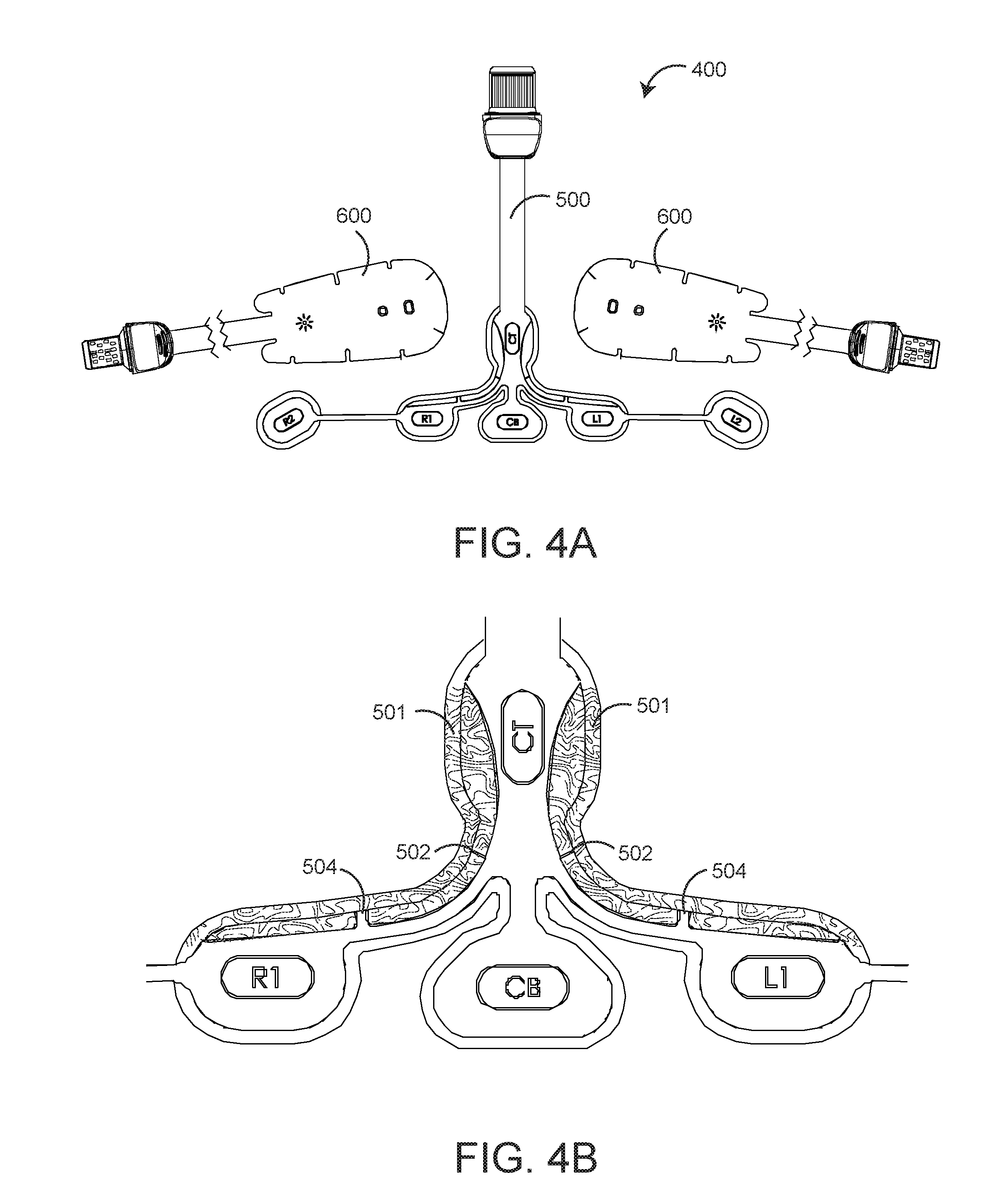
[0020] FIGS. 4A-B are an exploded plan view (FIG. 4A) and a detailed plan view (FIG. 4B), respectively, of a modular brain analysis sensor having an advantageous keyed mounting zone (shaded) for precise, overlaid placement of dual rO2 sensors on an rO2-configured EEG sensor;
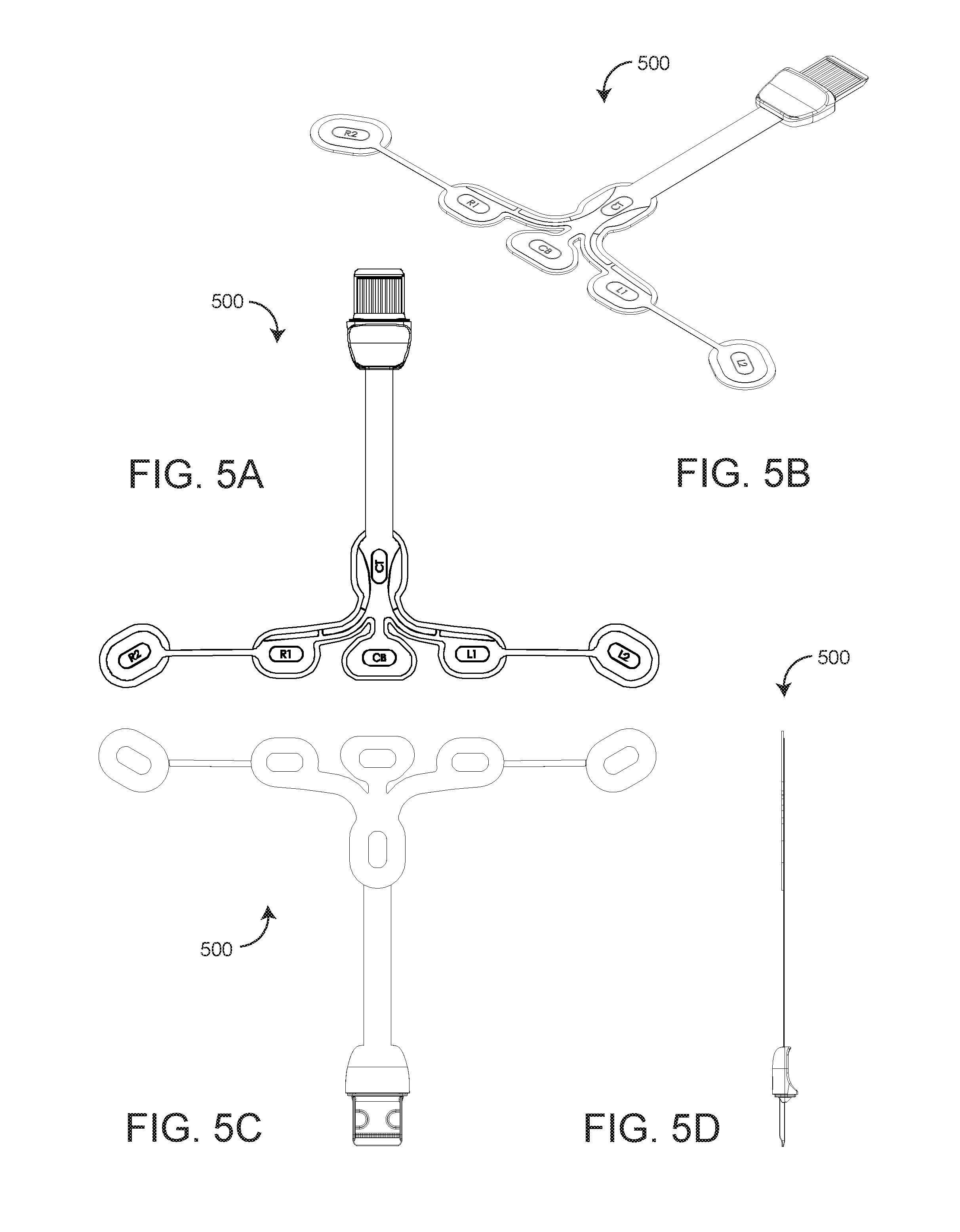
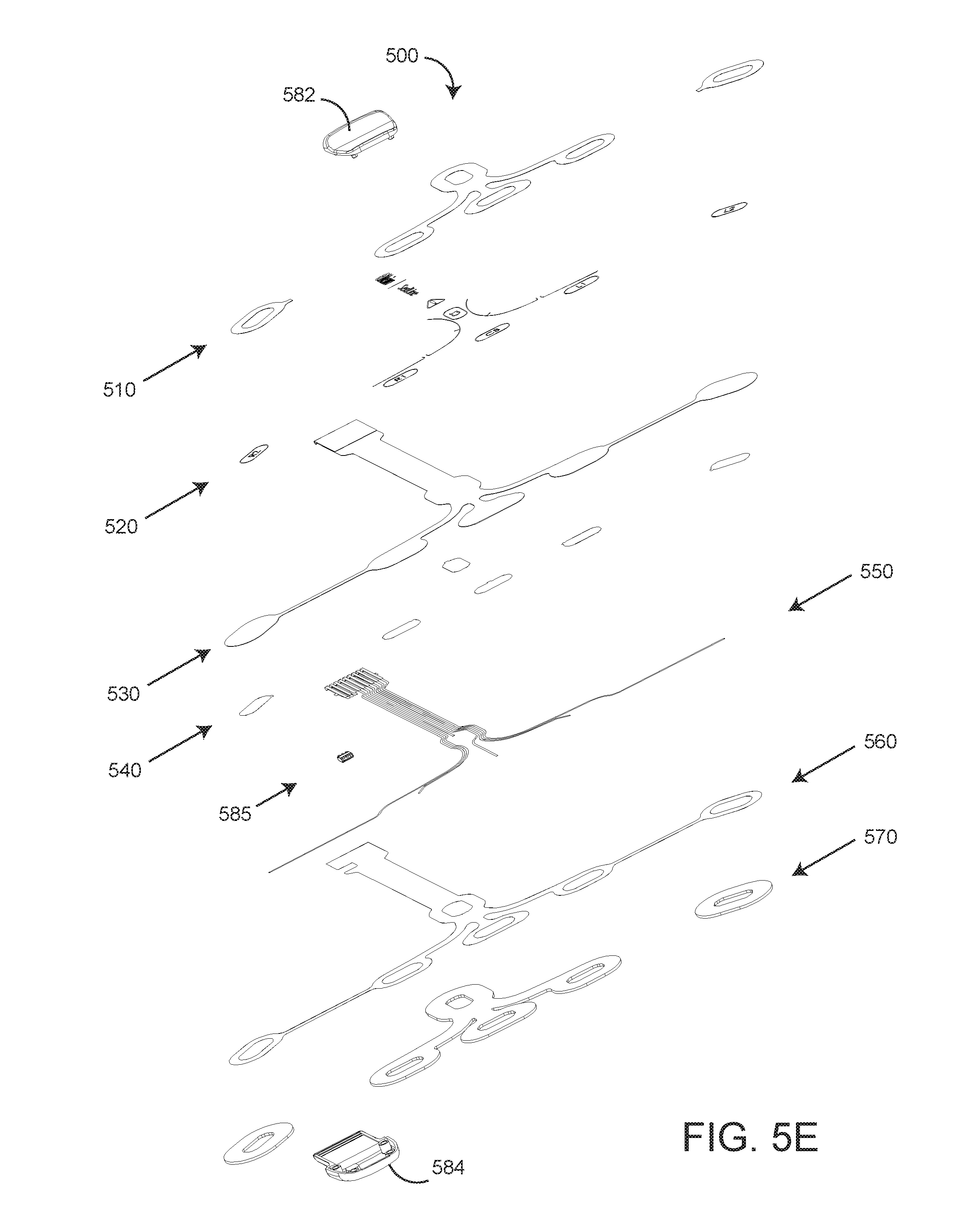
[0021] FIGS. 5A-E are top, perspective, bottom, side and exploded perspective views, respectively, of an rO2-configured EEG sensor; and
[0022] FIGS. 6A-E are top, side, bottom and exploded top perspective views, respectively, of a rO2 sensor and an enlarged perspective view of rO2 sensor optical elements.
DETAILED DESCRIPTION OF THE PREFERRED EMBODIMENT
[0023] FIG. 1 illustrates a brain analysis system 100 having an advantageous modular brain analysis sensor 400 applied to a forehead tissue site in communications with a physiological monitor 101 for measuring and generating simultaneous electroencephalogram (EEG) and left and right forehead regional oximetry (rO2) parameter values and waveforms. The modular brain analysis sensor 400 can be advantageously assembled and placed within a limited-area forehead site. Also, the rO2 components 600 and EEG component 500 can be advantageously purchased, stocked and used separately and individually, saving hospital and medical care center costs over other, more specialized brain analysis sensors not having separately useable regional oximetry and EEG sensor functions. The same cost savings is realized by modular designs for any and all types of physiological monitoring sensors.
[0024] As shown in FIG. 1, the brain analysis sensor 400 has an EEG sensor (FIGS. 4-5) that co-mounts dual regional oximetry (rO2) sensors. Each of these sensor functions are in communications with a physiological monitor 101 having a main display 120 and a (removable) handheld monitor 130 having a handheld display 132. The main display 120 provides EEG waveforms and parameter values 122 in addition to forehead left 124 and forehead right 125 regional oximeter waveforms and parameters. The handheld display 132 provides a 3-D man graphic displaying green, yellow and red organ symbols (brain, lung and kidneys) corresponding to EEG and/or rO2 parameter values. Similar displays can be provided for other physiological parameters as well.
[0025] Also shown in FIG. 1, a modular brain analysis sensor 400 advantageously has dual rO2 sensors 600 that overlap right- and left-side portions of a specially-configured and marked (rO2-configured) EEG sensor 500 so as to compactly fit these modular sensors 500, 600 within a limited-space forehead site, as described in detail with respect to FIGS. 2-4, below. An rO2-configured EEG sensor 500 is described in detail with respect to FIGS. 5A-E, below. An regional oximetry sensor 600 is described in detail with respect to FIGS. 6A-E, below.
[0026] Further shown in FIG. 1, in an EEG screen portion 122, the physiological monitor 101 display 120 shows 4 simultaneous EEG channels along with a patient state index (PSI) readout versus time so as to enable continuous assessment of both sides of the brain, such as for improved anesthetic management. In addition, forehead left 124 and forehead right 125 regional oximetry waveforms and readouts enable monitoring of brain tissue oxygen saturation and detect regional hypoxemia.
[0027] FIGS. 2-3 illustrate, respectively, a regional oximetry (rO2) sensor and cable assembly and an EEG sensor and cable assembly. As shown in FIG. 2, the regional oximetry (rO2) cable assembly 200 interconnects dual rO2 sensors 600 to a physiological monitor 101 (FIG. 1). The rO2 cable assembly has dual sensor connectors at a sensor end, a monitor connector (MOC9) at a monitor end and a rO2 pod mounted between and in communications with the sensor connectors and the monitor connector. Also shown in FIG. 2, the rO2 pod has regional oximetry analog and digital boards. The analog board communicates with one or more of the regional oximetry sensors 600. The digital board enables the pod to perform the sensor communications and signal processing functions of a conventional patient monitor. This allows pod-derived regional oximetry parameters to be displayed on a variety of monitors ranging from simple display devices to complex multiple parameter patient monitoring systems.
[0028] As shown in FIG. 3, the EEG cable assembly 300 interconnects an EEG sensor 500 to a physiological monitor 101 (FIG. 1). The EEG cable assembly 300 has an EEG connector at a sensor end, a monitor connector (MOC9) at a monitor end and a EEG pod mounted between and in communications with the sensor connectors and the monitor connector.
[0029] FIGS. 4A-B illustrate a modular brain analysis sensor 400 having advantageous keyed mounting zones 501 (shaded) for precise, overlaid placement of dual rO2 sensors on an EEG sensor. In particular, the EEG sensor 500 has two mounting zones 501, one on either side of the interconnected between the EEG electrodes and the EEG sensor connector. Each mounting zone accommodates one of two rO2 sensors (see FIG. 1 and FIG. 4A). Further, each mounting zone 501 (FIG. 4B) is shaped and printed to conform to a top and side portion of an rO2 sensor head 610 (FIGS. 6A-D). Further, each mounting zone has printed notches 502, 504 corresponding to actual notches in the rO2 sensor heads 610 (FIG. 6A) that accommodate curved tissue site surfaces. These printed notches 502, 504 further aid in the alignment of rO2 sensors to the mounting zones 501.
[0030] FIGS. 5A-E further illustrate an rO2 configured EEG sensor 500 having a generally "T" shape with six electrodes including two right electrodes R1, R2; two left electrodes L1, L2; a ground electrode CB and a reference electrode CT. As shown in FIG. 5A, the R1, R2, L1, L2 and CB electrodes are disposed across the horizontal top of the "T." The reference electrode CT is disposed on the vertical middle of the "T." The advantageous mounting zone 501 (FIG. 4B) is disposed on either side of the vertical middle of the "T" proximate the horizontal top of the "T."
[0031] As shown in FIG. 5E, the EEG sensor 500 has multiple layers including a release liner 510 that allows an attached rO2 sensor 600 (FIG. 1) to be removed and repositioned; artwork 520 including rO2 sensor positioning lines 502 (FIG. 4B); a polyester substrate 530; silver pads 540 (electrodes); silver ink traces 550; a dielectric layer 560 that isolates and protects the traces 550 and a foam pad 570 that contacts a user's skin. The EEG sensor connector includes a top shell 582 and a bottom shell 584. An information element 585 mechanically and electrically connects to the trace layer 550.
[0032] FIGS. 6A-E further illustrate a rO2 sensor and its optical elements having a sensor head 610, a stem 620 and a connector 630. The sensor head 610 houses an emitter 682, a near-field detector 684 and a far-field detector 688 within a layered tape having a top side (FIG. 6A) and an adhesive bottom side (FIG. 6C) disposed on a release liner. The release liner is removed so as to adhere the bottom side to a skin surface. The emitter 682 and detectors 684,688 have lens that protrude from the bottom side (FIG. 6E) advantageously providing a robust optics-skin interface. The top side has printed emitter/detector indicators so as to aid precise sensor placement on a patient site. A connector 630 terminates the interconnect 620 at the connector contacts 632.
[0033] Also shown in FIG. 6D, a sensor head assembly 610 has a face tape 612, a flex circuit 622, a stem tape 620, a base tape 624, a connector top 634 and a connector base 636. The face tape 612 and base tape 622 encase the flex circuit 622 and corresponding emitter and detectors 682-688.
[0034] A modular physiological sensor has been disclosed in detail in connection with various embodiments. These embodiments are disclosed by way of examples only and are not to limit the scope of this disclosure and the claims herein. One of ordinary skill in art will appreciate many variations and modifications. It should be understood specifically that the present mounting zones, tabs, relative shapes and modular configuration can be applied to other physiological sensors including, for example, ear, nose, hand, harm, and/or chest sensors or any other types of physiological sensors where the sensors are configured to jointly measure the same measurement site of a patient.
* * * * *
D00000
D00001
D00002
D00003
D00004
D00005
D00006
D00007
XML
uspto.report is an independent third-party trademark research tool that is not affiliated, endorsed, or sponsored by the United States Patent and Trademark Office (USPTO) or any other governmental organization. The information provided by uspto.report is based on publicly available data at the time of writing and is intended for informational purposes only.
While we strive to provide accurate and up-to-date information, we do not guarantee the accuracy, completeness, reliability, or suitability of the information displayed on this site. The use of this site is at your own risk. Any reliance you place on such information is therefore strictly at your own risk.
All official trademark data, including owner information, should be verified by visiting the official USPTO website at www.uspto.gov. This site is not intended to replace professional legal advice and should not be used as a substitute for consulting with a legal professional who is knowledgeable about trademark law.