Battery Assembly And Electronic Cigarette Having Same
CHEN; Wen
U.S. patent application number 16/034455 was filed with the patent office on 2019-05-09 for battery assembly and electronic cigarette having same. This patent application is currently assigned to SHENZHEN IVPS TECHNOLOGY CO., LTD.. The applicant listed for this patent is SHENZHEN IVPS TECHNOLOGY CO., LTD.. Invention is credited to Wen CHEN.
| Application Number | 20190133185 16/034455 |
| Document ID | / |
| Family ID | 62975867 |
| Filed Date | 2019-05-09 |


| United States Patent Application | 20190133185 |
| Kind Code | A1 |
| CHEN; Wen | May 9, 2019 |
BATTERY ASSEMBLY AND ELECTRONIC CIGARETTE HAVING SAME
Abstract
A battery assembly for an electronic cigarette includes a housing, a bracket, and a fastening member. The housing defines an opening, and a receiving space communicating with the opening. The bracket loads an object and is inserted into the receiving space via the opening. The fastening member is mounted to the housing, and configured to fasten the bracket inside the housing. The fastening member is operated from outside of the housing to release the bracket, the bracket with the object thus drops out of the housing via the opening.
| Inventors: | CHEN; Wen; (Shenzhen, CN) | ||||||||||
| Applicant: |
|
||||||||||
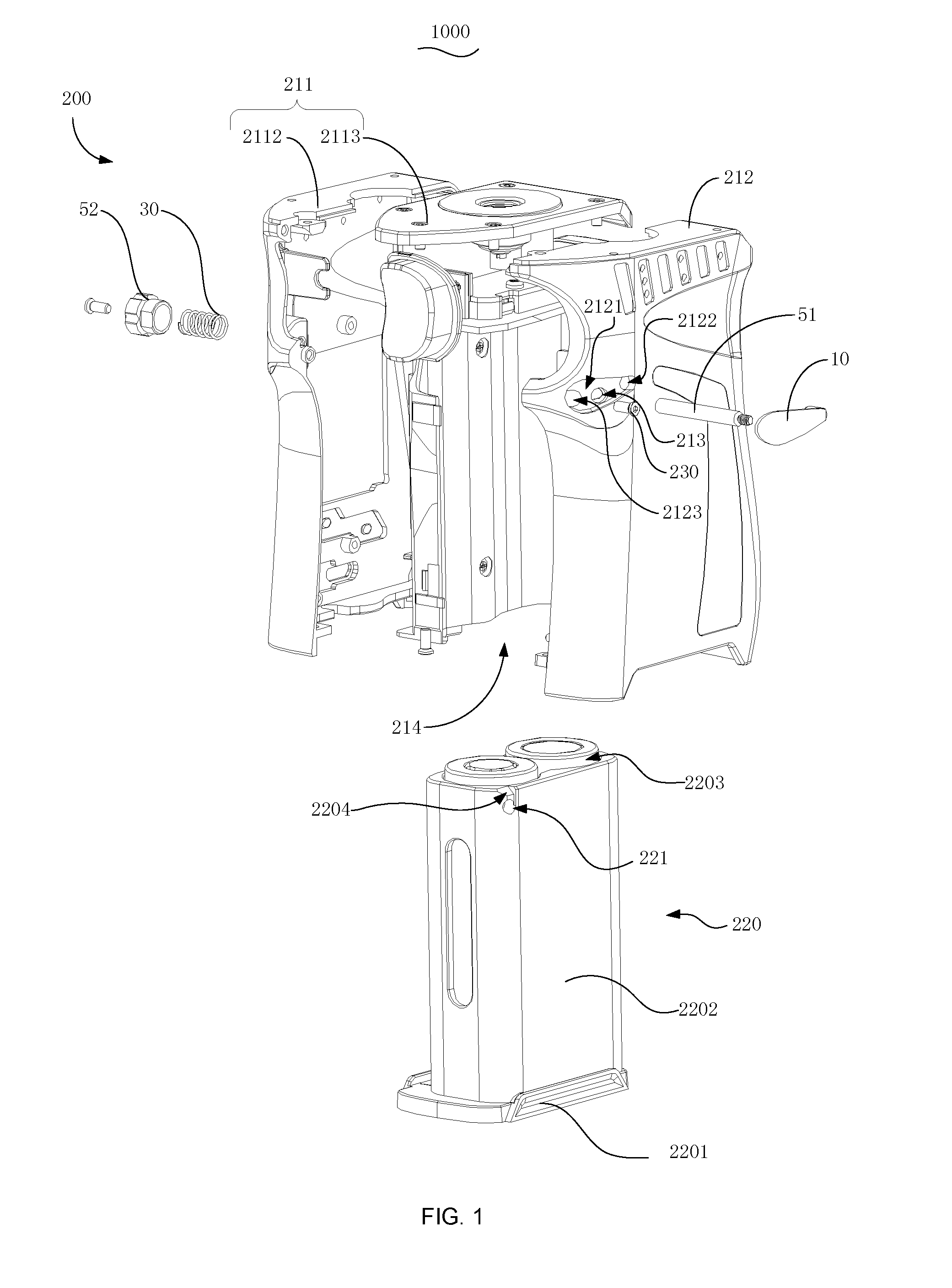
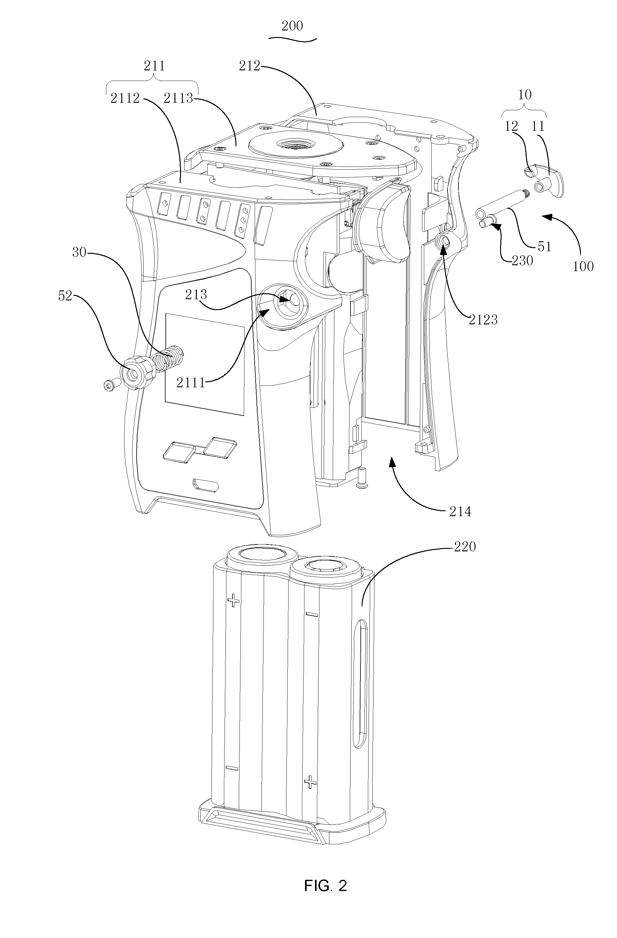
|---|---|---|---|---|---|---|---|---|---|---|---|
| Assignee: | SHENZHEN IVPS TECHNOLOGY CO.,
LTD. Shenzhen CN |
||||||||||
| Family ID: | 62975867 | ||||||||||
| Appl. No.: | 16/034455 | ||||||||||
| Filed: | July 13, 2018 |
| Current U.S. Class: | 1/1 |
| Current CPC Class: | A24F 47/008 20130101 |
| International Class: | A24F 47/00 20060101 A24F047/00 |
Foreign Application Data
| Date | Code | Application Number |
|---|---|---|
| Nov 7, 2017 | CN | 201721489661.0 |
Claims
1. A battery assembly for an electronic cigarette, comprising: a housing defining an opening, and a receiving space communicating with the opening; a bracket configured for loading an object, the bracket being inserted into the receiving space via the opening; and a fastening member mounted to the housing, the fastening member being configured to fasten the bracket inside the housing, the fastening member being operated from outside of the housing to release the bracket, so that the bracket with the object drop out of the housing via the opening.
2. The battery assembly according to claim 1, wherein the bracket defines a locking hole, the fastening member comprises a locking pin extending through the housing to insert into the locking hole to fasten the bracket.
3. The battery assembly according to claim 2, wherein the bracket comprises a bottom and a main body protruding from the bottom, the locking hole is defined in the main body, the opening is sealed by the bottom when the bracket is fastened inside the housing.
4. The battery assembly according to claim 3, wherein the locking hole is adjacent to a top end of the main body away from the bottom.
5. The battery assembly according to claim 4, wherein the bracket further forms a guiding surface inclined from the top end of the main body toward the locking hole.
6. The battery assembly according to claim 2, wherein the fastening member further comprises an operating element and a connecting element, the connecting element extends through the housing, the operating element and the locking element are respectively connected to two opposite ends of the connecting element, the operating element and the locking element are positioned outside of the housing, the locking element comprises a locking pin extending through the housing and inserting into the locking hole to fasten the bracket, the operating member is configured to drive the connecting element to enable the locking element to separate from the bracket.
7. The battery assembly according to claim 6, wherein the fastening member further comprises an elastic member, the elastic member is sleeved on the connecting element, and positioned between the operating element and the housing, the elastic member is deformed when the operating member is pressed, the elastic member is pressed to deform when the locking pin is pressed by the bracket inserted into the housing.
8. The battery assembly according to claim 7, wherein the housing comprises a first housing and a second housing, the first housing and the second housing are combined together to form the receiving space and the opening.
9. The battery assembly according to claim 8, wherein the housing further defines a mounting groove and a receiving groove, the mounting groove is concaved from a surface of one of the first housing and the second housing, the receiving groove is concaved from a surface of the other one of the first housing and the second housing, the operating member is positioned at the mounting groove, the locking member covers the receiving groove.
10. An electronic cigarette, comprising: a housing defining an opening, and a receiving space communicating with the opening; a bracket configured for loading an object, the bracket being inserted into the receiving space via the opening; and a fastening member mounted to the housing, the fastening member being configured to fasten the bracket inside the housing, the fastening member being further operated from outside of the housing to release the bracket, so that the bracket with the object drop out of the housing via the opening.
11. The electronic cigarette according to claim 10, wherein the bracket defines a locking hole, the fastening member comprises a locking pin extending through the housing to insert into the locking hole to fasten the bracket.
12. The electronic cigarette according to claim 11, wherein the bracket comprises a bottom and a main body protruding from the bottom, the locking hole is defined in the main body, the opening is sealed by the bottom when the bracket is fastened inside the housing.
13. The electronic cigarette according to claim 12, wherein the locking hole is adjacent to a top end of the main body away from the bottom.
14. The electronic cigarette according to claim 13, wherein the bracket further forms a guiding surface inclined from the top end of the main body toward the locking hole.
15. The electronic cigarette according to claim 11, wherein the fastening member further comprises an operating element, a connecting element, the connecting element extends through the housing, the operating element and the locking element are respectively connected to two opposite ends of the connecting element, the operating element and the locking element are positioned outside of the housing, the operating member is configured to drive the connecting element to enable the locking element to separate from the bracket.
16. The electronic cigarette according to claim 15, wherein the fastening member further comprises an elastic member, the elastic member is sleeved on the connecting element, and positioned between the operating element and the housing, the elastic member is deformed when the operating member is pressed, or the locking pin is pressed by the bracket when the bracket is inserted into the housing.
17. A battery assembly, comprising: a housing defining an opening, and a receiving space communicating with the opening; a fastening member mounted to the housing, the fastening member comprising: a connecting element, extending through the housing; an operating element, positioned outside of the housing and coupled to one end of the connecting element, and a locking element, positioned outside of the housing and coupled to the other end of the connecting element, the locking element comprising a locking pin extending through the housing; and a bracket configured for loading a battery, the bracket being configured to insert into the receiving space via the opening, the bracket defining a locking hole, the locking pin being inserted into the locking hole to fasten the bracket.
18. The battery assembly according to claim 17, wherein the bracket defines a locking hole, the fastening member comprises a locking pin extending through the housing to insert into the locking hole to fasten the bracket.
19. The battery assembly according to claim 17, wherein the bracket comprises a bottom and a main body protruding from the bottom, the locking hole is defined in the main body, the opening is sealed by the bottom when the bracket is fastened inside the housing.
20. The battery assembly according to claim 19, wherein the bracket further forms a guiding surface inclined from the top end of the main body toward the locking hole.
Description
CROSS REFERENCE TO RELATED APPLICATIONS
[0001] The present application claims the benefit of Chinese Patent Application NO. 201721489661.0 filed on Nov. 7, 2017; the contents of which are hereby incorporated by reference.
TECHNICAL FIELD
[0002] The present disclosure relates to electronic cigarettes, in particular to a battery assembly and an electronic cigarette having the battery assembly.
BACKGROUND
[0003] With the improvement of people's health consciousness, more and more people recognize that smoking is bad for health. In recent years, alternative cigarette products, such as electronic cigarettes, have been invented. A typical electronic cigarette is a depression and vapor electronic product. The typical is capable of storing and heating the tobacco product or simulate product to provide smokers with aerosol for smoking. With the improvement of people's health consciousness, the electronic cigarettes are rapidly developed, and more and more popular.
[0004] However, a changeable article, such as battery, is placed in a battery bracket. The bracket is mounted in a housing that battery is placed in or taken out of the housing. The bracket is usually mounted the housing via a fastening mechanism. The fastening mechanism is mounted inside of the housing and hardly disassembled. Furthermore, the fastening mechanism is easy to damage when disassembled.
[0005] Therefore, there is room for improvement in the art.
SUMMARY
[0006] A battery assembly for an electronic cigarette includes a housing, a bracket, and a fastening member. The housing defines an opening, and a receiving space communicating with the opening. The bracket loads an object and is inserted into the receiving space via the opening. The fastening member is mounted to the housing, and configured to fasten the bracket inside the housing. The fastening member is operated from outside of the housing to release the bracket, the bracket with the object thus drops out of the housing via the opening.
BRIEF DESCRIPTION OF THE DRAWINGS
[0007] For a better understanding of the embodiments of the present disclosure or the technical scheme in the prior art, accompanying drawings needed in the description of the embodiments or the prior art are simply illustrated below. Obviously, the accompanying drawings described below are some embodiments of the present disclosure. For the ordinary skill in the field, other accompanying drawings may be obtained according to the structure shown in these accompanying drawings without creative work.
[0008] FIG. 1 is a first explored isometric view of a battery assembly in accordance with an embodiment.
[0009] FIG. 2 is an explored isometric view of a battery assembly viewed from another respect in FIG. 1 accordance with an embodiment.
[0010] FIG. 3 is a second explored isometric view of a battery assembly in accordance with an embodiment.
DETAILED DESCRIPTION
[0011] A clear and complete description as below is provided for the technical scheme in the embodiments of the present disclosure in conjunction with the drawings in the embodiments of the present disclosure. Obviously, the embodiments described hereinafter are simply part embodiments of the present disclosure, but all the embodiments. All other embodiments obtained by the ordinary skill in the art based on the embodiments in the present disclosure without creative work are intended to be included in the scope of protection of the present disclosure.
[0012] It should be noted that all directional indications (such as top, bottom, left, right, front, behind . . . ) in the embodiments of the present disclosure are merely to illustrate a relative position relation, a relative motion condition, etc. between each part in a certain state (for example, the state shown in the drawings). If the state changes, the directional indication changes accordingly.
[0013] In addition, if terms "first", "second", etc. appear in the present disclosure, they are merely for the purpose of description, but cannot be understood as the indication or implication of relative importance or as the implicit indication of the number of the designated technical features; therefore, features defined by "first" and "second" may specifically or implicitly include one or more such features. In the description of the present disclosure, unless otherwise stated, "a plurality of" means at least two, for example, two, three, etc.
[0014] In the present disclosure, unless otherwise specifically stated and defined, terms "connected", "fixed", etc. should be interpreted expansively. For example, "fixed" may be fixed connection, also may be detachable connection, or integration; may be mechanical connection, also may be electrical connection; may be direct connection, also may be indirect connection through an intermediate, and may be internal communication between two elements or interaction of two elements, unless otherwise specifically defined. The ordinary skill in this field can understand the specific implication of the above terms in the present disclosure according to specific conditions.
[0015] In addition, technical schemes of each embodiment of the present disclosure maybe combined mutually; however, this must be carried out on the basis that the or ordinary skill in this field can implement the combination. When the combination of technical schemes has a conflict or cannot be implemented, it should considered that such combination of technical schemes does not exist and is not in the scope of protection claimed by the present disclosure.
[0016] The present disclosure relates to a battery compartment for an electronic cigarette, aiming to solve the problem of disassembling in related art.
[0017] FIGS. 1-3 illustrates an electronic cigarette 1000 in accordance with an embodiment. In this embodiment, the electronic cigarette 1000 includes a battery assembly 200 and an atomizer (not shown). The atomizer is detachably mounted to the battery assembly 200, and configured to power the atomizer. In other embodiments, the atomizer and the battery assembly 200 are undetachable. In other embodiments, the electronic cigarette 1000 is capable of heating solid tobacco or pipe tobacco without the atomizer.
[0018] In this embodiment, the battery assembly 200 includes a housing 210, a fastening mechanism 100, and a bracket 220. In other embodiments, the battery assembly 200 maybe also called the electronic cigarette, such as the battery assembly 200 is undetachably secured to the atomizer, or the battery assembly 20 is contained in an electronic cigarette which is capable of heating solid tobacco or pipe tobacco without the atomizer. The bracket 220 is configured for loading an object to be change, such as a battery. In this embodiment, the object is at least one battery. The housing 210 defines a receiving space 214 and forms an opening 2101 communicating with the receiving space 214. The bracket 220 is inserted into the receiving space 214 via the opening 2101. The fastening mechanism 100 is mounted to the housing 210 and configured to hold the bracket 220 inside of the housing 210. The fastening mechanism 100 is further configured to be operated from outside of the housing 210 to release the bracket 220, and the fastening mechanism 100 is disassembled from the housing 210. In detail, the bracket 220 is fetched from the housing 210 or falls out of the housing 210 via the opening 2101.
[0019] The bracket 220 includes a bottom 2201, and a main body 2202 protruding from the main bottom 2201. The main body 2202 defines at least one chamber 2203 for receiving the at least one battery, and a locking hole 221. The locking hole 221 is near the top end of the bracket 220 away from the bottom 2201. The main body 2202 further forms a guiding surface 2204 inclined from the top end of the bracket 220 toward the locking hole 221.
[0020] Referring to FIG. 1, the housing 210 includes a first housing 211, and a second housing 212 detachably combined with the first housing 211 to form the receiving groove 214 among the first housing 211 and the second housing 212. The housing 210 further defines a through hole 213, the through hole 213 extends through the first housing 211 and the second housing 212. The first housing 211 includes a casing 2112, and a mounting board 2113. The mounting board 2113 is secured to the casing 2112 and form a space to receive electronic components (not shown). The first housing 211 defines a mounting groove 211 concaved from an outside surface of the first housing 211. The second housing 212 defines a receiving groove 2121 concaved from an outside surface of the second housing 212. The through hole 213 is located in the mounting groove 211 and the receiving groove 2121. The second housing 212 further defines a connecting hole 2123 and a guiding hole 2122. The guiding hole 2122, and the connecting hole 2123 are located in the receiving groove 2121, the through hole 213 is located between the connecting hole 2123 and the guiding hole 2122. A securing member 230 extends the through the second housing 212 via the connecting hole 2123 and is then secured in the second housing 212. The first housing 211 is thus secured to the second housing 212.
[0021] The fastening member 100 includes a locking element 10, a connecting element 50, an elastic element 30, and an operating element 52. The locking element 10 and the operating element 52 are outside of the housing 210. The connecting element 50 extends through the housing 210 via the through hole 213, and two opposite ends of the connecting element 50 extend out of the housing 210. One end of the connecting element 50 is secured to the locking element 10, the other end of the connecting element 50 is secured to the operating element 30. The elastic element 30 is sleeved on the connecting element 50 and positioned between the housing 210 and the operating element 52. The locking element 10 includes a connecting board 12, and a locking pin 11 protruding from the connecting board 12 and extending inside the housing 210 via the guiding hole 2122. The connecting board 12 is positioned in the receiving groove 2121 and covers the receiving groove 2121. The securing member 230 further covers the securing member 230.
[0022] Referring to FIG. 1, in this embodiment, the operating element 52 is in a cap shaped. The side wall of the operating element 52 defines a plurality of concaves. The operating element 52 is secured to the connecting element 50 via a screw (not labeled) and positioned in the mounting groove 211. The screw is screwed from the top end of the operating element 52. In this embodiment, the operating element 52 is detachably secured to the connecting element 50, it is easy for the user to change or maintain damage elements. In other embodiments, the operating element 52 is integrally formed in the connecting element 50.
[0023] When the bracket 220 is inserted into the housing 210, the locking hole 221 corresponds to the locking pin 11, the guiding surface 2204 presses the bracket 220 and guides the locking pin 11 to insert into the locking hole 221, the bracket 220 is held by the fastening member 100. When the battery is desired to be disassembled from the housing 220, the operating element 52 is pressed to push the locking element 10 that the elastic element 30 is deformed, the locking pin 11 is pushed out of the locking hole 221, and the bracket 220 with the battery drop out of the housing 210. When the operating element 52 is released, the elastic element 30 rebounds and the locking element 10 is moved back.
[0024] The above are preferred embodiments of the present disclosure merely and are not intended to limit the patent scope of the present disclosure. Any equivalent structures made according to the description and the accompanying drawings of the present disclosure without departing from the idea of the present disclosure, or any equivalent structures applied in other relevant technical fields directly or indirectly are intended to be included in the patent protection scope of the present disclosure.
* * * * *
D00000
D00001
D00002
D00003
XML
uspto.report is an independent third-party trademark research tool that is not affiliated, endorsed, or sponsored by the United States Patent and Trademark Office (USPTO) or any other governmental organization. The information provided by uspto.report is based on publicly available data at the time of writing and is intended for informational purposes only.
While we strive to provide accurate and up-to-date information, we do not guarantee the accuracy, completeness, reliability, or suitability of the information displayed on this site. The use of this site is at your own risk. Any reliance you place on such information is therefore strictly at your own risk.
All official trademark data, including owner information, should be verified by visiting the official USPTO website at www.uspto.gov. This site is not intended to replace professional legal advice and should not be used as a substitute for consulting with a legal professional who is knowledgeable about trademark law.