Slide Rail Mechanism
Chen; Ken-Ching ; et al.
U.S. patent application number 15/961897 was filed with the patent office on 2019-05-02 for slide rail mechanism. The applicant listed for this patent is KING SLIDE TECHNOLOGY CO.,LTD., KING SLIDE WORKS CO., LTD.. Invention is credited to Ken-Ching Chen, Chien-Li Huang, Chun-Chiang Wang, Shun-Ho Yang.
| Application Number | 20190132986 15/961897 |
| Document ID | / |
| Family ID | 62165438 |
| Filed Date | 2019-05-02 |


| United States Patent Application | 20190132986 |
| Kind Code | A1 |
| Chen; Ken-Ching ; et al. | May 2, 2019 |
SLIDE RAIL MECHANISM
Abstract
A slide rail mechanism includes a slide rail and a bracket device. The bracket device is arranged to the slide rail. Wherein one of the slide rail and the bracket device includes a structure feature for communicating with two opposite sides of the slide rail mechanism.
| Inventors: | Chen; Ken-Ching; (Kaohsiung City, TW) ; Yang; Shun-Ho; (Kaohsiung City, TW) ; Huang; Chien-Li; (Kaohsiung City, TW) ; Wang; Chun-Chiang; (Kaohsiung City, TW) | ||||||||||
| Applicant: |
|
||||||||||
|---|---|---|---|---|---|---|---|---|---|---|---|
| Family ID: | 62165438 | ||||||||||
| Appl. No.: | 15/961897 | ||||||||||
| Filed: | April 25, 2018 |
| Current U.S. Class: | 1/1 |
| Current CPC Class: | H05K 7/1491 20130101; H05K 7/1489 20130101; H05K 7/183 20130101 |
| International Class: | H05K 7/14 20060101 H05K007/14; H05K 7/18 20060101 H05K007/18 |
Foreign Application Data
| Date | Code | Application Number |
|---|---|---|
| Oct 31, 2017 | TW | 106137836 |
Claims
1. A slide rail mechanism adapted to mount an electric apparatus to a rack, the slide rail mechanism comprising: a first rail; and a bracket device arranged to the first rail, the bracket device being mounted to the rack; wherein the electric apparatus is arranged on a first side of the slide rail mechanism, one of the first rail and the bracket device comprises a structure feature, and the structure feature communicates the first side and a second side opposite to the first side of the slide rail mechanism; wherein the structure feature is configured to allow a cable of the electric apparatus to pass through.
2. The slide rail mechanism of claim 1, wherein one of the first rail and the bracket device comprises a first wall, a second wall and a side wall connected between the first wall and the second wall, the first wall, the second wall and the side wall cooperatively define a space, the structure feature is disposed on the side wall, and the slide rail mechanism further comprises a strengthening part accommodated in the space.
3. The slide rail mechanism of claim 2, wherein the strengthening part comprises a first supporting wall, a second supporting wall and a middle wall connected between the first supporting wall and the second supporting wall, the first supporting wall, the second supporting wall and the middle wall are respectively located corresponding to the first wall, the second wall and the side wall, and the middle wall comprises a corresponding feature adjacent to the structure feature.
4. The slide rail mechanism of claim 3, wherein the strengthening part further comprises a first engaging portion, and the first engaging portion is configured to be engaged with a second engaging portion of the side wall.
5. The slide rail mechanism of claim 1, wherein the structure feature is a cable through hole.
6. The slide rail mechanism of claim 1, further comprising a second rail movable relative to the first rail.
7. The slide rail mechanism of claim 2, wherein the bracket device comprises a mounting member, and the mounting member is configured to be mounted to a post of the rack.
8. The slide rail mechanism of claim 7, wherein the bracket device is mounted on the first rail via a reinforcement member.
9. A slide rail mechanism, comprising: a first rail having a first end portion and a second end portion; a bracket connected adjacent to the second end portion of the first rail; and a bracket device connected adjacent to the first end portion of the first rail, a cable through hole is disposed on the bracket device.
10. The slide rail mechanism of claim 9, further comprising a reinforcement member connected to a backside of the first rail, the reinforcement member defining a space, the bracket device comprising a side wall movable relative to the first rail through the space of the reinforcement member, and the side wall comprising the cable through hole.
11. The slide rail mechanism of claim 10, further comprising a second rail movable relative to the first rail.
12. The slide rail mechanism of claim 10, wherein the bracket device further comprises a first wall and a second wall, the side wall is connected between the first wall and the second wall, the first wall, the second wall and the side wall cooperatively define a space, and the slide rail mechanism further comprises a strengthening part accommodated in the space of the bracket device.
13. The slide rail mechanism of claim 12, wherein the strengthening part comprises a first supporting wall, a second supporting wall and a middle wall connected between the first supporting wall and the second supporting wall, the first supporting wall, the second supporting wall and the middle wall are respectively located corresponding to the first wall, the second wall and the side wall, and the middle wall comprises a corresponding feature adjacent to the cable through hole.
14. The slide rail mechanism of claim 13, wherein the strengthening part further comprises a first engaging portion, and the first engaging portion is engaged with a second engaging portion of the side wall.
15. The slide rail mechanism of claim 13, wherein the strengthening part further comprises a first abutting portion configured to cooperate with a second abutting portion of the side wall.
16. A slide rail mechanism, comprising: a first rail; and a bracket device arranged to the first rail; wherein one of the first rail and the bracket device comprises a structure feature configured to communicate two sides of the slide rail mechanism.
17. The slide rail mechanism of claim 16, wherein one of the first rail and the bracket device comprises a first wall, a second wall and a side wall connected between the first wall and the second wall, the first wall, the second wall and the side wall cooperatively define a space, the structure feature is disposed on the side wall, and the slide rail mechanism further comprises a strengthening part accommodated in the space.
18. The slide rail mechanism of claim 17, wherein the strengthening part comprises a first supporting wall, a second supporting wall and a middle wall connected between the first supporting wall and the second supporting wall, the first supporting wall, the second supporting wall and the middle wall are respectively located corresponding to the first wall, the second wall and the side wall.
19. The slide rail mechanism of claim 18, wherein the structure feature is a cable through hole, and the middle wall comprises a supporting hole located corresponding to the cable through hole.
20. The slide rail mechanism of claim 17, wherein the strengthening part comprises a first engaging portion, and the first engaging portion is engaged with a second engaging portion of the side wall.
Description
BACKGROUND OF THE INVENTION
1. Field of the Invention
[0001] This invention relates to a slide rail mechanism, and more particularly, to a slide rail mechanism capable of mounting an electric apparatus to a rack.
2. Description of the Prior Art
[0002] As FIG. 1 and FIG. 2 shown, in a rack system, two sides of an electric apparatus, such as a first electric apparatus 100 with a first length (as shown in FIG. 1) or a second electric apparatus 102 with a second length (as shown in FIG. 2), are capable of being mounted to two pairs of posts 106a, 106b of a rack 106 via a pair of slide rail mechanisms 104a, 104b.
[0003] In related prior arts, maintainers usually need to walk to a rear side R along lateral sides of the slide mechanisms 104a, 104b or the rack 106 to obtain a cable 107 of these electric apparatuses 100, 102. The cable 107 can be a power line or a transmission line and is configured to be electrically connected to an object 108. The object 108, for example, is a power supply or an electric device. However, since the maintainers can only obtain the cable 107 of these electric apparatuses 100, 102 through the rear side R of the slide rail mechanisms 104a, 104b or the rack 106, it is inconvenient for the maintainers to maintain apparatus.
SUMMARY OF THE INVENTION
[0004] The present invention relates to a slide rail mechanism adapted to an electric device.
[0005] According to one aspect of the present invention, a slide rail mechanism adapted to mount an electric apparatus to a rack is provided. The slide rail mechanism includes a first rail and a bracket device. The bracket device is arranged to the first rail and mounted to the rack. Wherein, the electric apparatus is arranged on a first side of the slide rail mechanism, and one of the first rail and the bracket device includes a structure feature. The structure feature communicates the first side and a second side opposite to the first side of the slide rail mechanism. Wherein, the structure feature is configured to allow a cable of the electric apparatus to pass through.
[0006] Preferably, one of the first rail and the bracket device includes a first wall, a second wall and a side wall connected between the first wall and the second wall. The first wall, the second wall and the side wall cooperatively define a space. The structure feature is disposed on the side wall, and the slide rail mechanism further includes a strengthening part accommodated in the space.
[0007] Preferably, the strengthening part includes a first supporting wall, a second supporting wall and a middle wall connected between the first supporting wall and the second supporting wall. The first supporting wall, the second supporting wall and the middle wall are respectively located corresponding to the first wall, the second wall and the side wall, and the middle wall includes a corresponding feature adjacent to the structure feature.
[0008] Preferably, the strengthening part further includes a first engaging portion, and the first engaging portion is configured to be engaged with a second engaging portion of the side wall.
[0009] Preferably, the structure feature is a cable through hole.
[0010] Preferably, the slide rail mechanism further includes a second rail movable relative to the first rail.
[0011] Preferably, the bracket device includes a mounting member, and the mounting member is configured to be mounted to a post of the rack.
[0012] Preferably, the bracket device is mounted on the first rail via a reinforcement member.
[0013] According to another aspect of the present invention, a slide rail mechanism with a cable through hole or a structure feature communicating two sides of the slide rail mechanism is provided.
[0014] The slide rail mechanism including a first rail, a bracket and a bracket device is provided. The first rail has a first end portion and a second end portion. The bracket is connected adjacent to the second end portion of the first rail. The bracket device is connected adjacent to the first end portion of the first rail, and a cable through hole is disposed on the bracket device.
[0015] The slide rail mechanism including a first rail and a bracket device is provided. The bracket device is arranged to the first rail. Wherein, one of the first rail and the bracket device includes a structure feature configured to communicate two sides of the slide rail mechanism.
[0016] These and other objectives of the present invention will no doubt become obvious to those of ordinary skill in the art after reading the following detailed description of the preferred embodiment that is illustrated in the various figures and drawings.
BRIEF DESCRIPTION OF THE DRAWINGS
[0017] FIG. 1 is a diagram showing a first electric apparatus being mounted to a rack through a slide rail mechanism in the prior art.
[0018] FIG. 2 is a diagram showing a second electric apparatus being mounted to the rack through the slide rail mechanism in the prior art.
[0019] FIG. 3 is an exploded diagram of the slide rail mechanism according to an embodiment of the present invention.
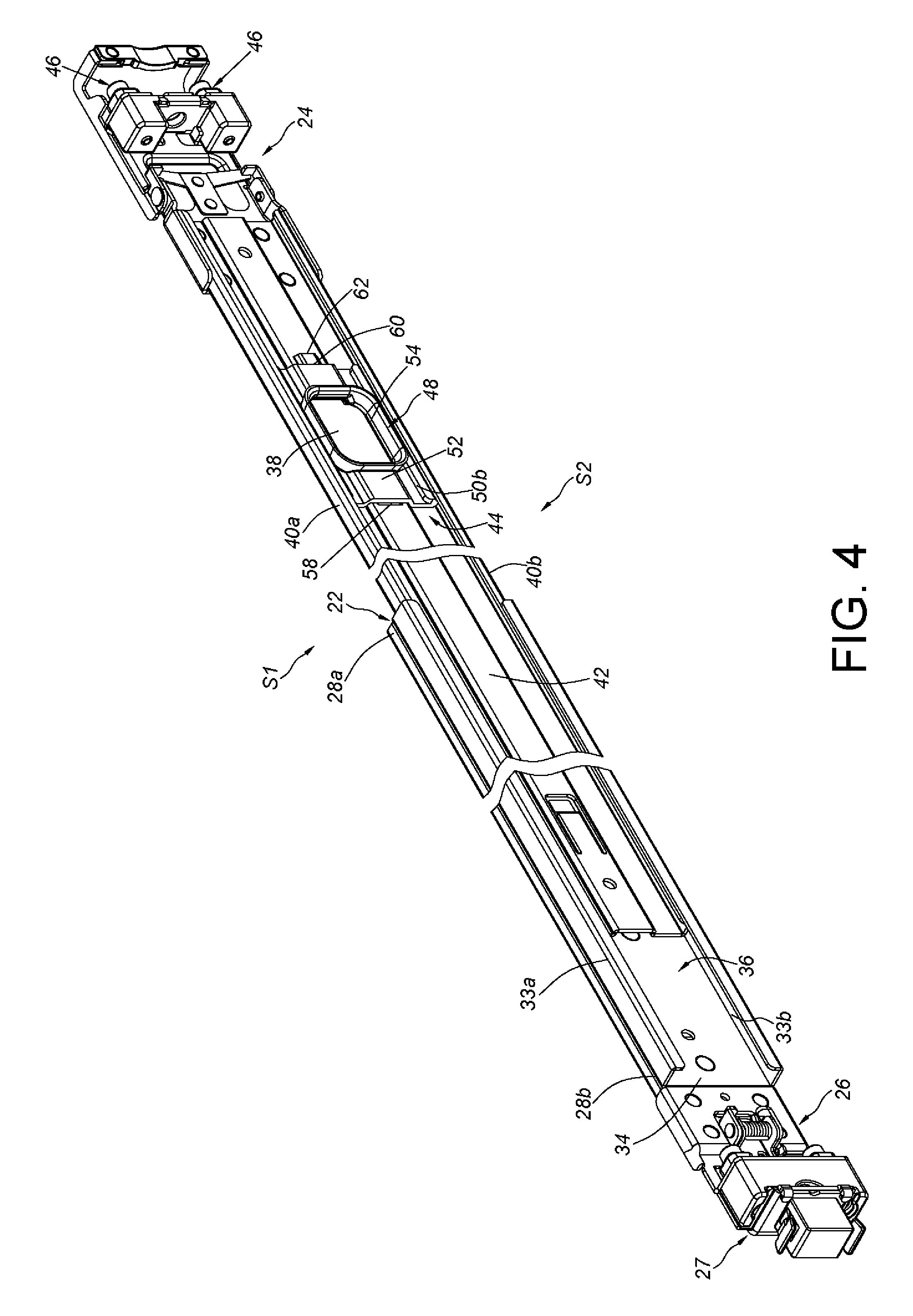
[0020] FIG. 4 is an assembly diagram of the slide rail mechanism according to the embodiment of the present invention.
[0021] FIG. 5 is a diagram showing that the slide rail mechanism mounts an electric apparatus to the rack, and a cable is disposed from a side to another side opposite to the side of the slide rail mechanism according to the embodiment of the present invention.
[0022] FIG. 6 is a diagram showing that the slide rail mechanism mounts an electric apparatus to the rack according to the embodiment of the present invention.
DETAILED DESCRIPTION
[0023] As shown in FIG. 3 and FIG. 4, a slide rail mechanism according to an embodiment of the present invention has a first side S1 and a second side S2. Preferably, the first side S1 and the second side S2 are opposite sides.
[0024] The slide rail mechanism includes a first rail 22 and a bracket device 24. Hereinafter, the slide rail mechanism further including a bracket 26 and a second rail 27 is illustrative of an example.
[0025] The first rail 22 has a first end portion 28a and a second end portion 28b. The first end portion 28a and the second end portion 28b, for example, are a frontal end portion and a rear end portion, respectively, but the present invention is not limited thereto. On the other hand, the second rail 27 is able to displace relative to the first rail 22, so as to be in a retracted position or in an extended position. Hereinafter, the second rail 27 arranged at a front side of the first rail 22 is illustrative of an example.
[0026] The bracket 26 is connected adjacent to the second end portion 28b of the first rail 22. On the other hand, the bracket device 24 is arranged on the first rail 22. Preferably, the bracket device 24 is connected adjacent to the first end portion 28a of the first rail 22 via a reinforcement member 30 disposed on a back side of the first rail 22, wherein the reinforcement member 30 and the first rail 22 can be integrated as an integral part. For example, the reinforcement member 30 is fixedly connected to the back side of the first rail 22 and can be regarded as one portion of the first rail 22. Preferably, the reinforcement member 30 includes a first wall 33a, a second wall 33b and a side wall 34 connected between the first wall 33a and the second wall 33b. The first wall 33a, the second wall 33b and the side wall 34 cooperatively define a space 36.
[0027] One of the bracket device 24 and the first rail 22 includes a structure feature 38. The structure feature 38 is configured to communicate a first side S1 and a second side S2 of the slide rail mechanism. Hereinafter, the bracket device 24 including the structure feature 38 is illustrative of an example. Preferably, the structure feature 38 is a cable through hole, but the present invention is not limited thereto. Moreover, the bracket device 24 includes a first wall 40a, a second wall 40b and a side wall 42 connected between the first wall 40a and the second wall 40b of the bracket device 24. The first wall 40a, the second wall 40b and the side wall 42 define a space 44. The side wall 42 of the bracket device 24 is mounted to the first rail 22 via the reinforcement member 30. Hereinafter, it is illustrative of an example that the side wall 42 of the bracket device 24 is able to move relative to the first rail 22 via the space 36 of the reinforcement member 30, and the cable through hole is formed on the side wall 42. Preferably, the bracket device 24 further includes a mounting member 46 and the mounting member 46 is arranged to an end position of the side wall 42 of the bracket device 24.
[0028] Preferably, the slide rail mechanism further includes a strengthening part 48 accommodated in the space 44 of the bracket device 24. The strengthening part 48 includes a first supporting wall 50a, a second supporting wall 50b and a middle wall 52 connected between the first supporting wall 50a and the second supporting wall 50b, wherein the first supporting wall 50a, the second supporting wall 50b and the middle wall 52 are respectively located corresponding to the first wall 40a, the second wall 40b and the side wall 42 of the bracket device 24 and are able to sustain each other. The middle wall 52 includes a corresponding feature 54 adjacent to the structure feature 38. In the embodiment, the corresponding feature 54 is a supporting hole, and a location of the supporting hole corresponds to that of the structure feature 38.
[0029] Preferably, the first supporting wall 50a and the first wall 40a are bending portions and are able to sustain each other. The second supporting wall 50b and the second wall 40b are bending portions and are able to sustain each other. Thereby, supporting intensity of the slide rail mechanism can be enhanced.
[0030] Preferably, the strengthening part 48 further includes a first engaging portion 56, and the first engaging portion 56 is configured to be engaged with a second engaging portion 58 of the side wall 42 of the bracket device 24. For example, the first engaging portion 56 and the second engaging portion 58 are a combination of a convex structure and a concave (or a hole) structure. The aforesaid combination enables the strengthening part 48 to be detachably connected to the bracket device 24.
[0031] In FIG. 3, it is noticed that the strengthening part 48 can further includes a flange 540. The flange 540 protrudes from the middle wall 52 of the strengthening part 48 and located around the corresponding feature 54 (i.e., the supporting hole). The flange 540 conduces to prevent abrasion between the cable and the strengthening part 48. In other words, the flange 540 reduces sharpness of an edge surrounding the corresponding feature 54 (i.e., the supporting hole), which results in protection of the cable from being damaged by the edge of the supporting hole. Besides, the flange 540 enhances structural strength of the strengthening part 48.
[0032] Preferably, the strengthening part 48 further includes a first abutting portion 60, and the first abutting portion 60 is configured to cooperate with a second abutting portion 62 of the side wall 42 of the bracket device 24. For example, the first abutting portion 60 and the second abutting portion 62 can abut against each other, so as to increase structural strength and/or reliability as the strengthening part 48 is mounted on the side wall 42.
[0033] As shown in FIG. 5, the slide rail mechanism is adapted to mount an electric apparatus 64 to a rack 66. Specifically, the electric apparatus 64, for example, is a server, a hard disk or a power distribution unit and so on, but the present invention is not limited thereto. The rack 66 includes a first post 66a and a second post 66b, and these posts 66a, 66b both have a plurality of mounting holes 68 (the mounting holes of the second post 66b are not shown due to the perspective).
[0034] Furthermore, the first rail 22 of the slide rail mechanism is mounted to the first post 66a via the bracket 26, and the first rail 22 is mounted to the second post 66b via (the said mounting part 46 of) the bracket device 24. Since this part is well-known by one of ordinary skill in the art, the detailed description is omitted herein for simplicity.
[0035] The electric apparatus 64 is arranged on the first side S1 of the slide rail mechanism. The electric apparatus 64 can be disposed on one of the first rail 22 and the second rail 27 in order that the electric apparatus 64 is mounted and supported. Hereinafter, the electric apparatus 64 disposed on the second rail 27 is illustrative of an example. Thereby, the electric apparatus 64 can be moved from an inside of the rack 66 to an outside of the rack 66, or be moved into the rack 66 from the outside of the rack 66 via the second rail 27.
[0036] The structure feature 38 communicates the first side S1 and the second side S2 of the slide rail mechanism. Specially, the structure feature 38 allows a cable 70 to pass through. For example, the cable 70 can pass through the structure feature 38 (and the corresponding feature 54 of the strengthening part 48) from the first side S1 of the slide rail mechanism. As a result, the cable 70 is exposed on the second side S2 or disposed to the second side S2. The aforesaid arrangement facilitates the maintainer to access the cable 70 on the lateral side (e.g., the second side S2) directly, so as to enhance convenience of operation.
[0037] As shown in FIG. 6, the electric apparatus 64 is mounted to two pairs of first posts 66a and second posts 66b via a pair of slide rail mechanism. Wherein, one of the pair of the slide rail mechanism has the structure feature 38, and maintainers can get the cable 70 directly on the side (for example, the second side S2) of the slide rail or the rack 66 through the structure feature 38. In other words, according to this configuration, the problem that maintainers need to walk to one end position of the slide rail mechanism or the rack 66 (for example, the rear position B) to obtain the cable 70 can be solved.
[0038] Accordingly, the embodiment of the present invention includes following features:
[0039] 1. The slide mechanism has a first side S1 and a second side S2, and one of the bracket device 24 and the first rail 22 includes the structure feature 38, which communicates the first side S1 and the second side S2 of the slide rail mechanism. When the electric apparatus 64 is arranged on the first side S1 of the slide rail mechanism, maintainers can obtain the cable 70 of the electric apparatus 64 on the second side S2 of the slide rail mechanism.
[0040] 2. The strengthening part 48 and the bracket device 24 can sustain each other so as to increase the structural intensity. The strengthening part 48 has the corresponding feature 54 which is adjacent to the structure feature 38 so as to assist the slide rail mechanism to support the cable 70.
[0041] 3. The strengthening part 48 is detachably connected to the bracket device 24, so that it can be attached depending on needs.
[0042] Those skilled in the art will readily observe that numerous modifications and alterations of the device and method may be made while retaining the teachings of the invention. Accordingly, the above disclosure should be construed as limited only by the metes and bounds of the appended claims.
* * * * *
D00000
D00001
D00002
D00003
D00004
D00005
D00006
XML
uspto.report is an independent third-party trademark research tool that is not affiliated, endorsed, or sponsored by the United States Patent and Trademark Office (USPTO) or any other governmental organization. The information provided by uspto.report is based on publicly available data at the time of writing and is intended for informational purposes only.
While we strive to provide accurate and up-to-date information, we do not guarantee the accuracy, completeness, reliability, or suitability of the information displayed on this site. The use of this site is at your own risk. Any reliance you place on such information is therefore strictly at your own risk.
All official trademark data, including owner information, should be verified by visiting the official USPTO website at www.uspto.gov. This site is not intended to replace professional legal advice and should not be used as a substitute for consulting with a legal professional who is knowledgeable about trademark law.