Garage Door Opener With Touch Sensor Authentication
BECK; Chasen Scott
U.S. patent application number 16/086553 was filed with the patent office on 2019-05-02 for garage door opener with touch sensor authentication. The applicant listed for this patent is Spectrum Brands, Inc.. Invention is credited to Chasen Scott BECK.
| Application Number | 20190130673 16/086553 |
| Document ID | / |
| Family ID | 59900680 |
| Filed Date | 2019-05-02 |


| United States Patent Application | 20190130673 |
| Kind Code | A1 |
| BECK; Chasen Scott | May 2, 2019 |
GARAGE DOOR OPENER WITH TOUCH SENSOR AUTHENTICATION
Abstract
A remote control unit for a garage door having a garage door opener. The remote control unit includes a controller, at least one wireless communication unit in electrical communication with the controller and a user interface in electrical communication with the controller. In some embodiments, the user interface includes a wireless authentication activation element that is configured to detect user-actuation of the wireless authentication activation element. The controller is configured to transmit a wireless control signal to open/close a garage door responsive to receiving a valid authentication code via the wireless communication unit. Typically, the controller is configured to receive a wireless authentication code responsive to actuation of the wireless authentication activation element.
| Inventors: | BECK; Chasen Scott; (Costa Mesa, CA) | ||||||||||
| Applicant: |
|
||||||||||
|---|---|---|---|---|---|---|---|---|---|---|---|
| Family ID: | 59900680 | ||||||||||
| Appl. No.: | 16/086553 | ||||||||||
| Filed: | March 21, 2017 | ||||||||||
| PCT Filed: | March 21, 2017 | ||||||||||
| PCT NO: | PCT/US2017/023311 | ||||||||||
| 371 Date: | September 19, 2018 |
Related U.S. Patent Documents
| Application Number | Filing Date | Patent Number | ||
|---|---|---|---|---|
| 62311552 | Mar 22, 2016 | |||
| Current U.S. Class: | 1/1 |
| Current CPC Class: | H04W 12/06 20130101; G06F 21/44 20130101; G07C 9/00896 20130101; G06F 21/34 20130101; H04L 12/2803 20130101; G07C 9/00 20130101; H04W 84/12 20130101; G07C 2009/0019 20130101; G07C 9/00182 20130101; G07C 9/0069 20130101; G06F 21/35 20130101; G07C 2009/00769 20130101; G07C 2009/00928 20130101 |
| International Class: | G07C 9/00 20060101 G07C009/00; H04W 12/06 20060101 H04W012/06; G06F 21/44 20060101 G06F021/44; G06F 21/35 20060101 G06F021/35 |
Claims
1. A remote control unit for a garage door having a garage door opener, the remote control unit comprising: a controller; at least one wireless communication unit in electrical communication with the controller; a user interface in electrical communication with the controller, wherein the user interface includes a wireless authentication activation element that is configured to detect user-actuation of the wireless authentication activation element; wherein the controller is configured to transmit a wireless control signal to open/close a garage door responsive to receiving a valid authentication code via the wireless communication unit; and wherein, responsive to actuation of the wireless authentication activation element, the controller is configured to receive a wireless authentication code.
2. The remote control unit of claim 1, wherein the wireless authentication activation element is a touch sensor circuit with a touch surface and wherein the controller is configured to receive a wireless authentication code responsive to user-selection of the touch surface.
3. The remote control unit of claim 1, wherein the wireless authentication activation element is at least one of a mechanical button, a mechanical switch, a proximity sensor, a capacitive sensor, an inductive sensor, a piezo element, and a resistive element.
4. The remote control unit of claim 1, wherein the at least one wireless communication unit includes a first wireless communication unit and a second wireless communication unit.
5. The remote control unit of claim 4, wherein the first wireless communication unit is configured to communicate at a frequency of approximately 2.46 GHz ISM Band, 915 MHz ISM Band, or Cellular Bands.
6. The remote control unit of claim 5, wherein the first wireless communication unit is configured to communicate using at least one of a Bluetooth, a Zigbee, a Zwave, and a WiFi protocol.
7. The remote control unit of claim 4, wherein the first wireless communication unit is configured to communicate at a frequency of at least one of approximately 300-400 MHz, ISM Bands, and Cellular Bands.
8. The remote control unit of claim 1, wherein the user interface further includes a keypad for entering an authentication code.
9. The remote control unit of claim 8, further comprising a cover movable between a first position that covers the keypad and a second position that does not cover the keypad.
10. The remote control unit of claim 9, wherein the cover does not cover the wireless authentication activation element in either the first position or the second position.
11. The remote control unit of claim 9, wherein the cover includes an opening dimensioned to receive the wireless authentication activation element.
12. The remote control unit of claim 11, wherein the wireless authentication activation element extends through the opening in the cover when the cover is in the first position.
13. The remote control unit of claim 1, further comprising a light communication unit surrounding the wireless authentication activation element.
14. The remote control unit of claim 13, wherein the light communication unit has a ring-like shape.
15. A method of remotely controlling a garage door having a garage door opener, the method comprising the steps of: detecting, with an electronic sensor, a touch event on a touch surface; initiating a wireless authentication process responsive to detection of a touch event; receiving, via a wireless communication, an electronic authentication code; determining whether the electronic authentication code is valid; responsive to determining that the electronic authentication code is valid, transmitting a wireless control signal to open or close a garage door; and responsive to determining that the electronic authentication code is invalid, denying access.
16. The method of claim 15, further comprising receiving the electronic authentication from user-selected input on a keypad.
17. The method of claim 15, wherein the electronic authentication code is wirelessly received via at least one of a Bluetooth, a Zwave, a Zigbee, and a WiFi protocol.
18. The method of claim 15, wherein the touch surface is metal.
19. The method of claim 15, wherein the touch surface is at least one of a mechanical button, a mechanical switch, a touch sensor, a proximity sensor, a capacitive sensor, an inductive sensor, a piezo element, and a resistive element.
Description
RELATED APPLICATIONS
[0001] This application claims the benefit of U.S. Provisional Application Ser. No. 62/311,552 filed Mar. 22, 2016, which is hereby incorporated by reference in its entirety.
TECHNICAL FIELD
[0002] The present disclosure relates generally to garage door openers. In particular, the present disclosure is directed to a garage door opener with a touch surface that initiates a wireless authentication process.
BACKGROUND
[0003] The garage door is a main point of entry and egress for many people. In most cases, the garage door is activated by a mechanical switch on the interior of the garage or by a remote signaling device located in the user's car. In other cases, the garage door can be controlled with a remote keypad or mechanical key cylinder mounted on the exterior frame of the door frame. However, there is a need for a remote garage door controller that adds convenience and security over conventional keypads used with garage doors.
SUMMARY
[0004] According to one aspect, this disclosure provides a remote control unit for a garage door having a garage door opener. The remote control unit includes a controller, at least one wireless communication unit in electrical communication with the controller and a user interface in electrical communication with the controller. In some embodiments, the user interface includes a wireless authentication activation element that is configured to detect user-actuation of the wireless authentication activation element. The controller is configured to transmit a wireless control signal to open/close a garage door responsive to receiving a valid authentication code via the wireless communication unit. Typically, the controller is configured to receive a wireless authentication code responsive to actuation of the wireless authentication activation element.
[0005] According to another aspect, this disclosure provides a method of remotely controlling a garage door having a garage door opener. The method includes the step of detecting, with an electronic sensor, a touch event on a touch surface. A wireless authentication process is initiated responsive to detection of a touch event. The method includes receiving via a wireless communication an electronic authentication code. A determination is made whether the electronic authentication code is valid. In response to determining that the electronic authentication code is valid, a wireless control signal is transmitted to open or close a garage door. If a determination is made that the electronic authentication code is invalid, access is denied.
BRIEF DESCRIPTION OF THE FIGURES
[0006] The detailed description makes reference to the accompanying figures in which:
[0007] FIG. 1 is a perspective view of garage door controlled by a garage door opener according to an embodiment of the disclosure;
[0008] FIG. 2 is a perspective view of the garage door opener shown in FIG. 1;
[0009] FIG. 3 is a perspective view of the garage door opener shown in FIG. 2 with a cover in an open position;
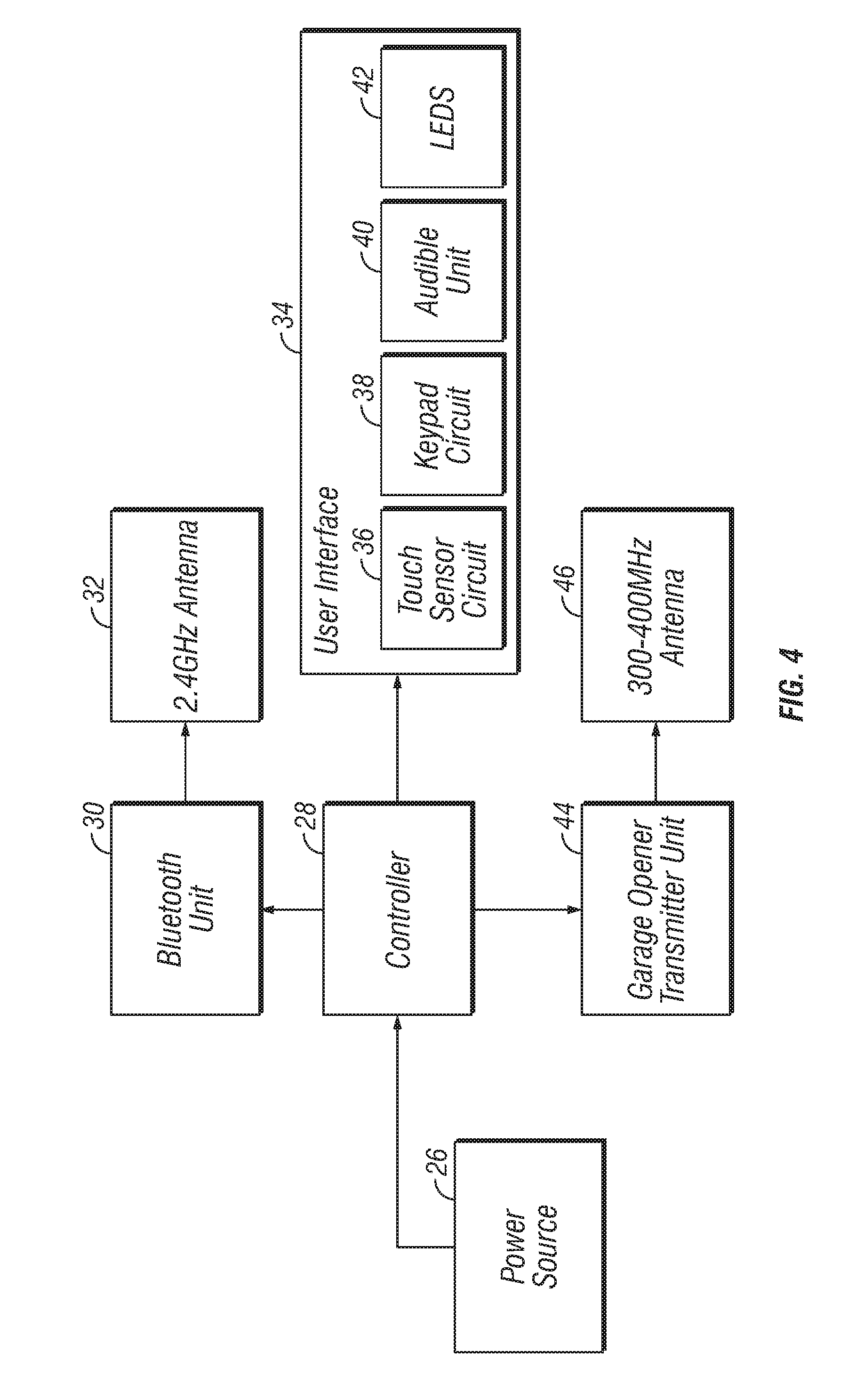
[0010] FIG. 4 is a simplified block diagram of a garage door opener according to an embodiment of the disclosure; and
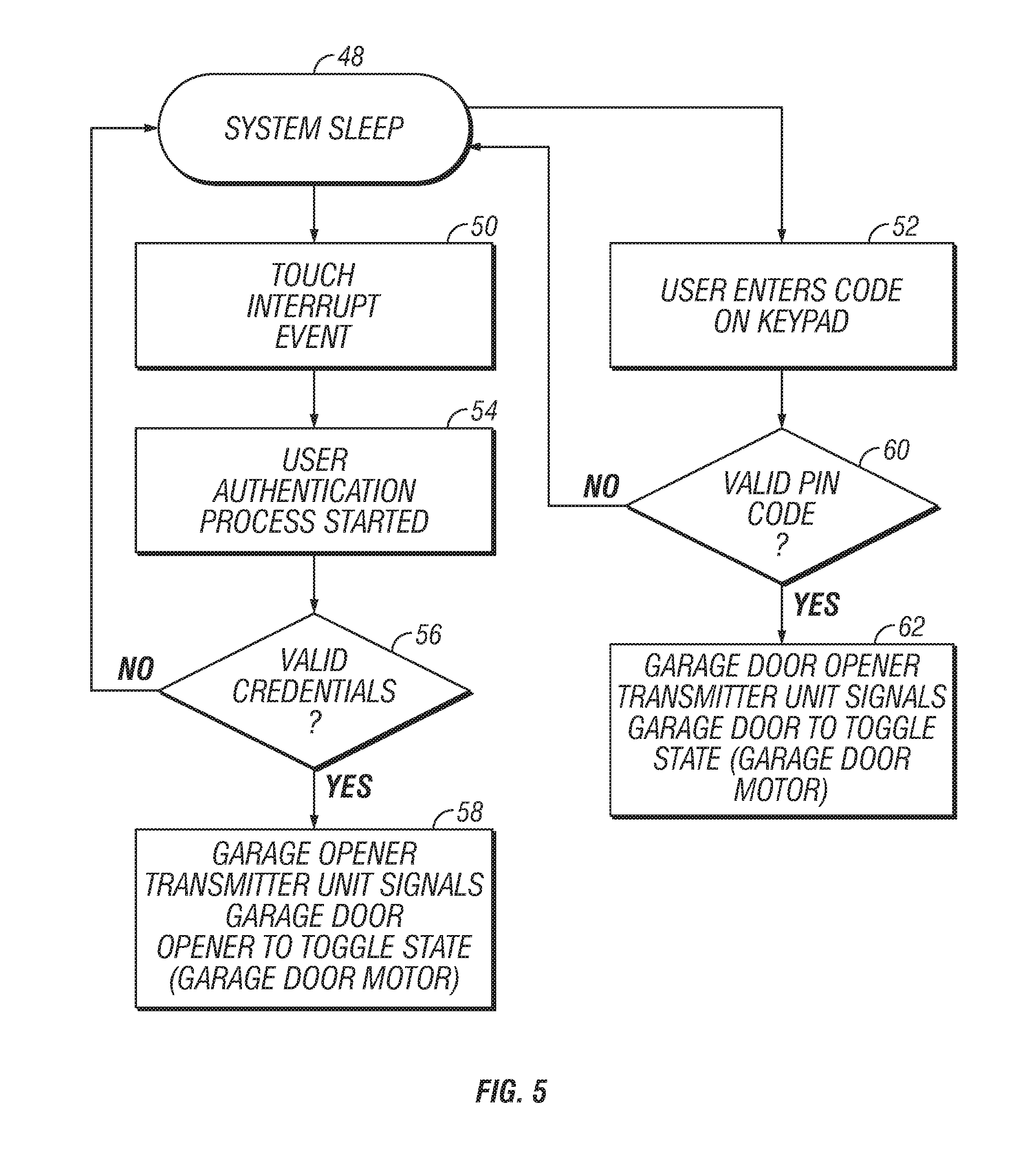
[0011] FIG. 5 is a simplified flow chart showing example operations that could be performed by the garage door opener according to an embodiment of the disclosure.
DETAILED DESCRIPTION
[0012] The figures and descriptions provided herein may have been simplified to illustrate aspects that are relevant for a clear understanding of the herein described devices, systems, and methods, while eliminating, for the purpose of clarity, other aspects that may be found in typical devices, systems, and methods. Those of ordinary skill may recognize that other elements and/or operations may be desirable and/or necessary to implement the devices, systems, and methods described herein. Because such elements and operations are well known in the art, and because they do not facilitate a better understanding of the present disclosure, a discussion of such elements and operations may not be provided herein. However, the present disclosure is deemed to inherently include all such elements, variations, and modifications to the described aspects that would be known to those of ordinary skill in the art.
[0013] References in the specification to "one embodiment," "an embodiment," "an illustrative embodiment," etc., indicate that the embodiment described may include a particular feature, structure, or characteristic, but every embodiment may or may not necessarily include that particular feature, structure, or characteristic. Moreover, such phrases are not necessarily referring to the same embodiment. Further, when a particular feature, structure, or characteristic is described in connection with an embodiment, it is submitted that it is within the knowledge of one skilled in the art to affect such feature, structure, or characteristic in connection with other embodiments whether or not explicitly described. Additionally, it should be appreciated that items included in a list in the form of "at least one A, B, and C" can mean (A); (B); (C); (A and B); (A and C); (B and C); or (A, B, and C). Similarly, items listed in the form of "at least one of A, B, or C" can mean (A); (B); (C); (A and B); (A and C); (B and C); or (A, B, and C).
[0014] In the drawings, some structural or method features may be shown in specific arrangements and/or orderings. However, it should be appreciated that such specific arrangements and/or orderings may not be required. Rather, in some embodiments, such features may be arranged in a different manner and/or order than shown in the illustrative figures. Additionally, the inclusion of a structural or method feature in a particular figure is not meant to imply that such feature is required in all embodiments and, in some embodiments, may not be included or may be combined with other features.
[0015] FIG. 1 shows an example garage door 10 the opening and closing of which is controlled, at least in part, by a remote control unit 12. The garage door 10 is connected with a garage door opener (not shown) that opens/closes the garage door 10 in a conventional manner, such as with a belt-drive or chain-drive system. The garage door opener is in wireless communication with the remote control unit 12 and is configured to open/close the garage door 10 based on a control signal wirelessly received from the remote control unit 12. For example, the remote control unit 12 could send a wireless command signal to the garage door opener to open/close the garage door 10. A double garage door is shown for purposes of illustration, but the type, size and shape of the garage door 10 that is controlled by the remote control unit 12 could vary depending on the circumstances.
[0016] FIGS. 2 and 3 illustrate the example remote control unit 12 with a cover 14 in a closed position and in an open position to reveal a keypad 16, respectively. In the embodiment shown, the cover 14 is pivotally connected to a base housing 18. Although the cover 14 pivots generally about a horizontal axis in the example shown, one skilled in the art should appreciate the cover 14 could pivot about the vertical axis or otherwise be connected to the base housing 18 to aid in weatherproofing. In some embodiments, the cover 14 may be optional, such as if the base housing 18 is weatherproof; in some embodiments, the keypad and/or wireless authentication activation element could be on the base housing 18 and no cover 14 may be provided.
[0017] As shown, the remote control unit 12 includes a wireless authentication activation element, which is a touch surface 20 in the embodiment shown that can be used to initiate authentication of the user, such as through wireless communication of an electronic authentication key. The touch surface 20 is shown for purposes of example, but the wireless authentication activation element could be embodied as a touch sensor, proximity sensor, a physical button, a physical switch, a piezo element, inductive element or a resistive element or other element that could be user-selected or detect the user's presence in proximity to the remote control unit 12. Although the touch surface 20 is circular in the example shown, one skilled in the art should appreciate that the touch surface could be any desired shape. In some cases, the touch surface 20 could be a capacitive touch surface in which user-selection of the surface 20 could be detected by the remote control unit 12 to initiate an authentication process. In some embodiments, the remote control unit 12 is configured to perform a wireless authentication process, such as using Bluetooth.TM. communications (or some other wireless protocol), with a key fob or mobile device to determine whether the user is authenticated. If the user is authenticated based on wireless communications with the user's key fob or wireless device, the remote control unit 12 will transmit a wireless control signal to the garage door opener to open/close the garage door 10.
[0018] In the embodiment shown, the remote control unit includes a light communication device 22 that is configured to communicate status information and/or operational information to the user concerning the remote control unit 12 and/or the garage door 10. For example, the light communication device 22 could light up to indicate that the key fob or mobile device of the user is in range of the remote control unit 12. In some cases, the light communication device 22 could change colors and/or have other animations based on operation, such as opening/closing of door. In the example shown, the light communication device 22 has a ring-like shape that surrounds the touch surface 20. However, the light communication device 22 could be any shape depending on the circumstances.
[0019] As shown, the cover 14 includes an opening 24 (see FIG. 2) sized to receive the touch surface 12 so that the touch surface 20 is accessible therethrough. With this embodiment, the user would not need to open the cover 14 to open/close the garage door 10. Instead, the user could merely touch the touch surface 20 with a key fob or mobile device in the user's pocket (or bag or other area) to open/close the garage door 10. By touching the touch surface 20, this will cause the remote control unit 12 to initiate communications with the key fob or mobile device for purposes of authentication. If the key fob or mobile device is authenticated, the remote control unit 12 would then transmit a wireless control signal to the garage door opener, which would open/close the garage door 10.
[0020] FIG. 3 shows the remote control unit 12 with the cover 14 in the open position, which reveals the keypad 16. With the cover 14 in the open position, the user could either use the touch surface 20 or the keypad 16 for authentication to open/close the garage door 10. The keypad 16 would operate as a conventional keypad in which the user could select an open/close button upon entering a pin code. The remote control unit 12 would determine whether the pin code is valid, and if so, transmit a signal the garage door opener to open/close the garage door 10.
[0021] Referring to FIG. 4, there is shown a simplified block diagram showing an embodiment of the remote control unit 12. In this embodiment, the remote control unit 12 includes a power source 26, such as batteries or a hardwired power source, which provides electrical power to electrical components in the remote control unit 12. As shown, the remote control unit 12 includes a controller 28 that is configured to control operation of the remote control unit 12. The controller 28 may be embodied as a single or multi-core processor(s), microcontroller, or other processor or processing/controlling circuit. The controller 28 is electrically connected to a Bluetooth.TM. unit 30, which is configured to send and receive wireless communications using the Bluetooth.TM. protocol via a 2.4 GHz antenna 32. Although the Bluetooth.TM. unit 30 is shown for purposes of example, other protocols could be used to wirelessly authenticate the user.
[0022] In the embodiment shown, the controller 28 is electrically connected with a user interface 34. As this example, the user interface 34 includes a touch sensor circuit 36, a keypad 38, an audible unit 40 and LEDs 42. The touch sensor circuit 36 is configured to detect a user touching the touch surface 20. Upon detecting such a touch of the touch surface 20, the touch sensor circuit 36 would provide a signal to the controller 28 indicating that the touch surface 20 has been actuated. The controller 28, in turn, would send a wireless communication with the Bluetooth.TM. unit 30 to authenticate the user's key fob or mobile device using Bluetooth.TM. communications. The keypad circuit 38 is configured to provide input received through the keypad 16 to the controller 28 for authentication (or other purposes for which the keypad 16 could be used). In this example, the user interface 34 includes an audible unit 40, which could be configured to generate sounds as desired during operation of the remote control unit 12. The controller 28 could be configured to turn on/off the LEDs 42 as desired, such as for backlighting of the keypad 16, for the light communication device 22, etc.
[0023] As shown, the controller 28 is electrically connected to a garage opener transmitter unit 44, which is configured to send and receive wireless communications to the garage door opener via a 300-400 MHz antenna 46 to open/close the garage door 10. Many garage door openers operate in the 300-400 MHz spectrum, which is why the antenna in that spectrum is shown for purposes of example. However, the garage opener transmitter unit could be configured to transmit a control signal to the garage door opener on any frequency as desired.
[0024] FIG. 5 is a flow chart showing example operations that could be performed by the remote control unit 12. In this example, the remote control unit 12 is in sleep mode (Block 48) until the touch sensor circuit 36 detects a user-selection of the touch surface 20 (Block 50) or the user enters a pin code on the keypad 16 (Block 52). If the user selects the touch surface 20, the controller 28 initiates a user authentication process (Block 54). In some embodiments, the controller 28 wirelessly receives an electronic authentication code from a key fob or mobile device. The controller 28 determines whether the electronic authentication code is valid (Block 56), and if so, transmits a control signal via the garage opener transmitter unit 44 to the garage door opener to open/close the garage door 10 (Block 58). If the user enters a pin code on the keypad (Block 52), the controller 28 determines whether the code is valid (Block 60). If so, the remote control unit 12 transmits a control signal via the garage opener transmitter unit 44 to the garage door opener to open/close the garage door 10 (Block 62).
EXAMPLES
[0025] Illustrative examples of the remote control unit for a garage door disclosed herein are provided below. An embodiment of the remote control unit may include any one or more, and any combination of, the examples described below.
[0026] Example 1 includes a remote control unit for a garage door having a garage door opener, the remote control unit comprising a controller, at least one wireless communication unit in electrical communication with the controller, a user interface in electrical communication with the controller, wherein the user interface includes a wireless authentication activation element that is configured to detect user-actuation of the wireless authentication activation element, wherein the controller is configured to transmit a wireless control signal to open/close a garage door responsive to receiving a valid authentication code via the wireless communication unit, and wherein, responsive to actuation of the wireless authentication activation element, the controller is configured to receive a wireless authentication code.
[0027] Example 2 includes the subject matter of Example 1, and wherein the wireless authentication activation element is a touch sensor circuit with a touch surface and wherein the controller is configured to receive a wireless authentication code responsive to user-selection of the touch surface.
[0028] Example 3 includes the subject matter of Example 1, and wherein the wireless authentication activation element is one or more of a mechanical button, a mechanical switch, a touch sensor, a proximity sensor, a capacitive sensor, inductive sensor, a piezo element, and/or a resistive element.
[0029] Example 4 includes the subject matter of Example 1, and wherein the at least one wireless communication unit includes a first wireless communication unit and a second wireless communication unit.
[0030] Example 5 includes the subject matter of Example 4, and wherein the first wireless communication unit is configured to communicate at a frequency of approximately 2.4 6 GHz ISM Band, 915 MHz ISM Band, or Cellular Bands.
[0031] Example 6 includes the subject matter of Example 5, and wherein the first wireless communication unit is configured to communicate using a Bluetooth, Zigbee, Zwave, WiFi protocol.
[0032] Example 7 includes the subject matter of Example 4, and wherein the first wireless communication unit is configured to communicate at a frequency of approximately 300-400 MHz, ISM Band, or Cellular Bands.
[0033] Example 8 includes the subject matter of Example 1, and wherein the user interface further includes a keypad for entering an authentication code.
[0034] Example 9 includes the subject matter of Example 8, and further comprising a cover movable between a first position that covers the keypad and a second position that does not cover the keypad.
[0035] Example 10 includes the subject matter of Example 9, and wherein the cover does not cover the touch surface in either the first position or the second position.
[0036] Example 11 includes the subject matter of Example 9, and wherein the cover includes an opening dimensioned to receive the touch surface.
[0037] Example 12 includes the subject matter of Example 11, and wherein the touch surface extends through the opening in the cover when the cover is in the first position.
[0038] Example 13 includes the subject matter of Example 1, and further comprising a light communication unit surrounding the touch surface.
[0039] Example 14 includes the subject matter of Example 13, and wherein the light communication unit has a ring-like shape.
[0040] Example 15 is a method of remotely controlling a garage door having a garage door opener. The method comprises the steps of detecting, with an electronic sensor, a touch event on a touch surface, initiating a wireless authentication process responsive to detection of a touch event, receiving via a wireless communication an electronic authentication code, determining whether the electronic authentication code is valid, responsive to determining that the electronic authentication code is valid, transmitting a wireless control signal to open or close a garage door, and responsive to determining that the electronic authentication code is invalid, denying access.
[0041] Example 16 includes the subject matter of Example 15, further comprising receiving the electronic authentication from user-selected input on a keypad.
[0042] Example 17 includes the subject matter of Example 15, and wherein the electronic authentication code is wirelessly received via a Bluetooth, Zwave, Zigbee, WiFi communication.
[0043] Example 18 includes the subject matter of Example 15, and wherein the touch surface is metal.
[0044] Example 19 includes the subject matter of Example 18, and wherein the touch surface is a mechanical button, a mechanical switch, a touch sensor, a proximity sensor, a capacitive sensor, inductive sensor, a piezo element, and/or a resistive element.
* * * * *
D00000
D00001
D00002
D00003
D00004
D00005
XML
uspto.report is an independent third-party trademark research tool that is not affiliated, endorsed, or sponsored by the United States Patent and Trademark Office (USPTO) or any other governmental organization. The information provided by uspto.report is based on publicly available data at the time of writing and is intended for informational purposes only.
While we strive to provide accurate and up-to-date information, we do not guarantee the accuracy, completeness, reliability, or suitability of the information displayed on this site. The use of this site is at your own risk. Any reliance you place on such information is therefore strictly at your own risk.
All official trademark data, including owner information, should be verified by visiting the official USPTO website at www.uspto.gov. This site is not intended to replace professional legal advice and should not be used as a substitute for consulting with a legal professional who is knowledgeable about trademark law.