Portable Electronic Device
LEE; Kun-Ho ; et al.
U.S. patent application number 15/962447 was filed with the patent office on 2019-05-02 for portable electronic device. The applicant listed for this patent is Quanta Computer Inc.. Invention is credited to Chih-Min CHAN, Kun-Ho LEE.
| Application Number | 20190129546 15/962447 |
| Document ID | / |
| Family ID | 66242940 |
| Filed Date | 2019-05-02 |


| United States Patent Application | 20190129546 |
| Kind Code | A1 |
| LEE; Kun-Ho ; et al. | May 2, 2019 |
PORTABLE ELECTRONIC DEVICE
Abstract
A portable electronic device is provided. The portable electronic device includes a display unit, an input unit and a hinge member. The hinge member is detachably connected to the display unit and pivotally connected to the input unit, and the hinge member and the display unit are rotatable relative to the input unit around a rotary axis. The display unit has at least a slot and the hinge member has at least a guide pin corresponding to the slot. The guide pin has a first slope structure and a vertical surface structure. The first slope structure and the vertical surface structure are arranged in a direction parallel to the rotary axis.
| Inventors: | LEE; Kun-Ho; (Taoyuan City, TW) ; CHAN; Chih-Min; (Taoyuan City, TW) | ||||||||||
| Applicant: |
|
||||||||||
|---|---|---|---|---|---|---|---|---|---|---|---|
| Family ID: | 66242940 | ||||||||||
| Appl. No.: | 15/962447 | ||||||||||
| Filed: | April 25, 2018 |
| Current U.S. Class: | 1/1 |
| Current CPC Class: | G06F 1/1643 20130101; G06F 1/1654 20130101; G06F 1/1681 20130101; G06F 3/0412 20130101; G06F 1/1616 20130101 |
| International Class: | G06F 3/041 20060101 G06F003/041; G06F 1/16 20060101 G06F001/16 |
Foreign Application Data
| Date | Code | Application Number |
|---|---|---|
| Oct 26, 2017 | TW | 106136886 |
Claims
1. A portable electronic device, comprising: a display unit, having at least a slot; an input unit; and a hinge member, detachably connected to the display unit and pivotally connected to the input unit, and the hinge member and the display unit are rotatable relative to the input unit around a rotary axis, wherein the hinge member has at least a guide pin corresponding to the slot, and the guide pin has a first slope structure and a vertical surface structure, wherein the first slope structure and the vertical surface structure are arranged in a direction parallel to the rotary axis.
2. The portable electronic device as claimed in claim 1, wherein the length of the first slope structure in the direction of the rotary axis is less than or equal to one half of the length of the guide pin in the direction of the rotary axis.
3. The portable electronic device as claimed in claim 1, wherein the length of the first slope structure in the direction of the rotary axis is less than or equal to one-third of the length of the guide pin in the direction of the rotary axis.
4. The portable electronic device as claimed in claim 1, further comprising at least a connecting assembly movably disposed in the slot and abutting against the first slope structure.
5. The portable electronic device as claimed in claim 4, wherein the connecting assembly includes a sliding member and a spring, and the spring is disposed around the sliding member.
6. The portable electronic device as claimed in claim 5, wherein the sliding member has a main body and a rod portion, the spring is disposed around the rod portion, and the main body has a second slope structure in contact with first slope structure.
7. The portable electronic device as claimed in claim 4, wherein the slot has a first portion corresponding to the vertical surface structure, and the first portion is configured to receive the vertical surface structure.
8. The portable electronic device as claimed in claim 7, wherein the slot further has a second portion corresponding to the first slope structure, and the connecting assembly is disposed in the second portion of the slot.
9. The portable electronic device as claimed in claim 8, wherein the depth of the second portion is greater than that of the first portion.
10. The portable electronic device as claimed in claim 1, wherein the input unit has at least a protrusion and the hinge member further has at least a recess configured to receive the protrusion.
Description
CROSS REFERENCE TO RELATED APPLICATIONS
[0001] This application claims the benefit of Taiwan Patent Application No. 106136886, filed on Oct. 26, 2017, the entirety of which is incorporated by reference herein.
BACKGROUND OF THE INVENTION
Field of the Invention
[0002] The application relates in general to a portable electronic device, and in particular to a portable electronic device with multiple modes of use.
Description of the Related Art
[0003] Due to the popularity of tablet computers and touch display screens, users have become accustomed to operating electronic devices by touch. Some laptop computers are equipped with detachable touch display screens (tablets) and are switchable between a laptop (notebook) mode and a tablet mode via the connecting mechanism thereof to facilitate the operations of the user. However, although the connecting mechanisms of the laptops are suitable for this purpose, when the touch display screen (tablet) is connected to the connecting mechanism, the screen may still sway, or the connection strength between the screen and the connecting mechanism is insufficient.
BRIEF SUMMARY OF INVENTION
[0004] To address the deficiencies of conventional products, an embodiment of the invention provides a portable electronic device that primarily includes a display unit, an input unit, and a hinge member. The hinge member is detachably connected to the display unit and pivotally connected to the input unit. The hinge member and the display unit are rotatable relative to the input unit around a rotary axis. The display unit has at least a slot and the hinge member has at least a guide pin corresponding to the slot. The guide pin has a first slope structure and a vertical surface structure. The first slope structure and the vertical surface structure are arranged in a direction parallel to the rotary axis.
[0005] In some embodiments, the length of the first slope structure in the direction of the rotary axis is less than or equal to one half of the length of the guide pin in the direction of the rotary axis.
[0006] In some embodiments, the length of the first slope structure in the direction of the rotary axis is less than or equal to one-third of the length of the guide pin in the direction of the rotary axis.
[0007] In some embodiments, the portable electronic device further comprises at least a connecting assembly movably disposed in the slot and abutting against the first slope structure.
[0008] In some embodiments, the connecting assembly includes a sliding member and a spring, wherein the spring is disposed around the sliding member.
[0009] In some embodiments, the sliding member has a main body and a rod portion, wherein the spring is disposed around the rod portion and the main body has a second slope structure in contact with first slope structure.
[0010] In some embodiments, the slot has a first portion corresponding to the vertical surface structure, and the first portion is configured to receive the vertical surface structure.
[0011] In some embodiments, the slot further has a second portion corresponding to the first slope structure, and the connecting assembly is disposed in the second portion of the slot.
[0012] In some embodiments, the depth of the second portion is greater than the first portion.
[0013] In some embodiments, the input unit has at least a protrusion and the hinge member further has at least a recess configured to receive the protrusion.
BRIEF DESCRIPTION OF DRAWINGS
[0014] The invention can be more fully understood by reading the subsequent detailed description and examples with references made to the accompanying drawings, wherein:
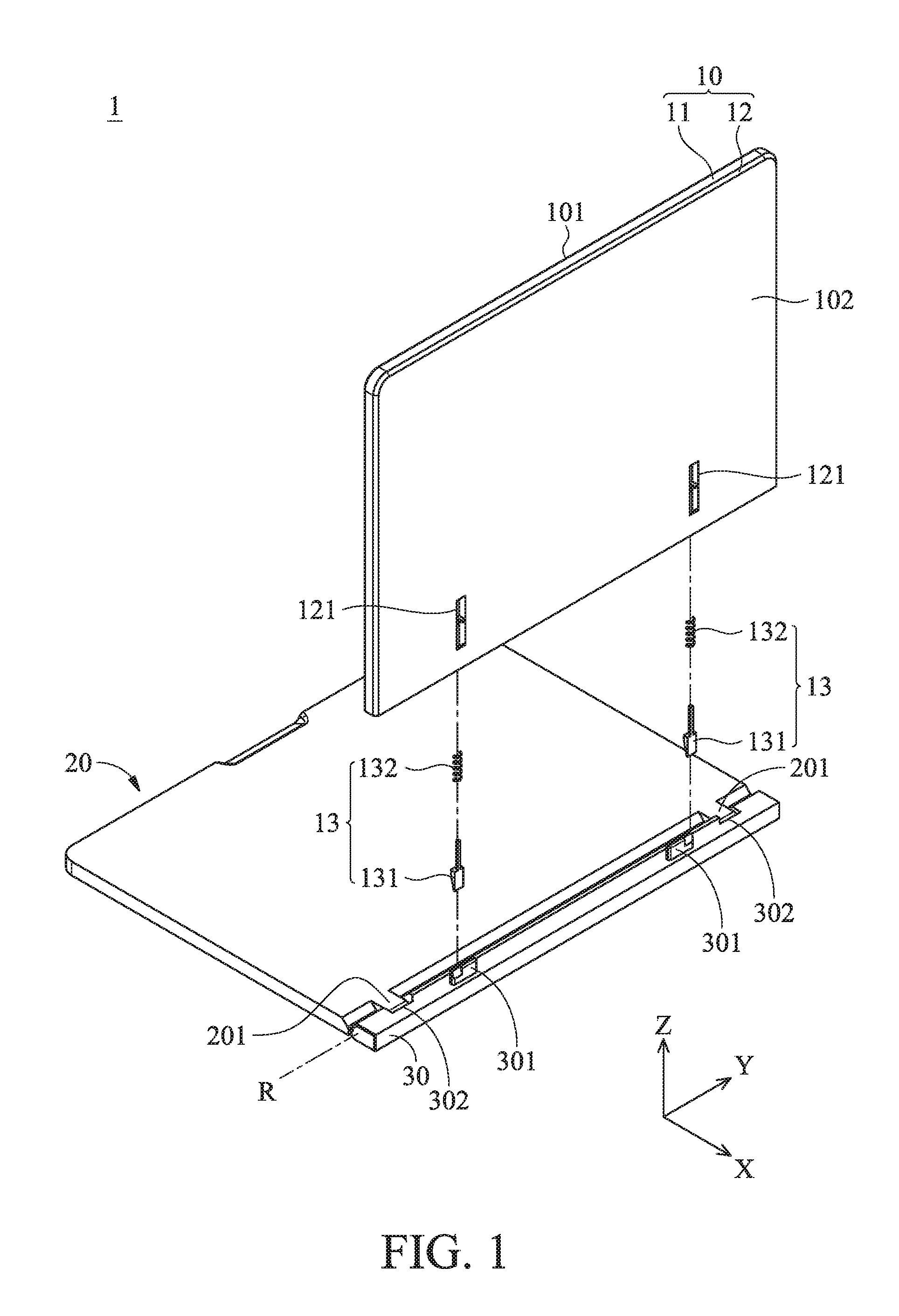
[0015] FIG. 1 is an exploded diagram of a portable electronic device according to an embodiment of the invention.
[0016] FIG. 2A is an enlarged view diagram of the guide pin in FIG. 1.
[0017] FIG. 2B is a schematic diagram of the connecting assembly in FIG. 1 after assembly.
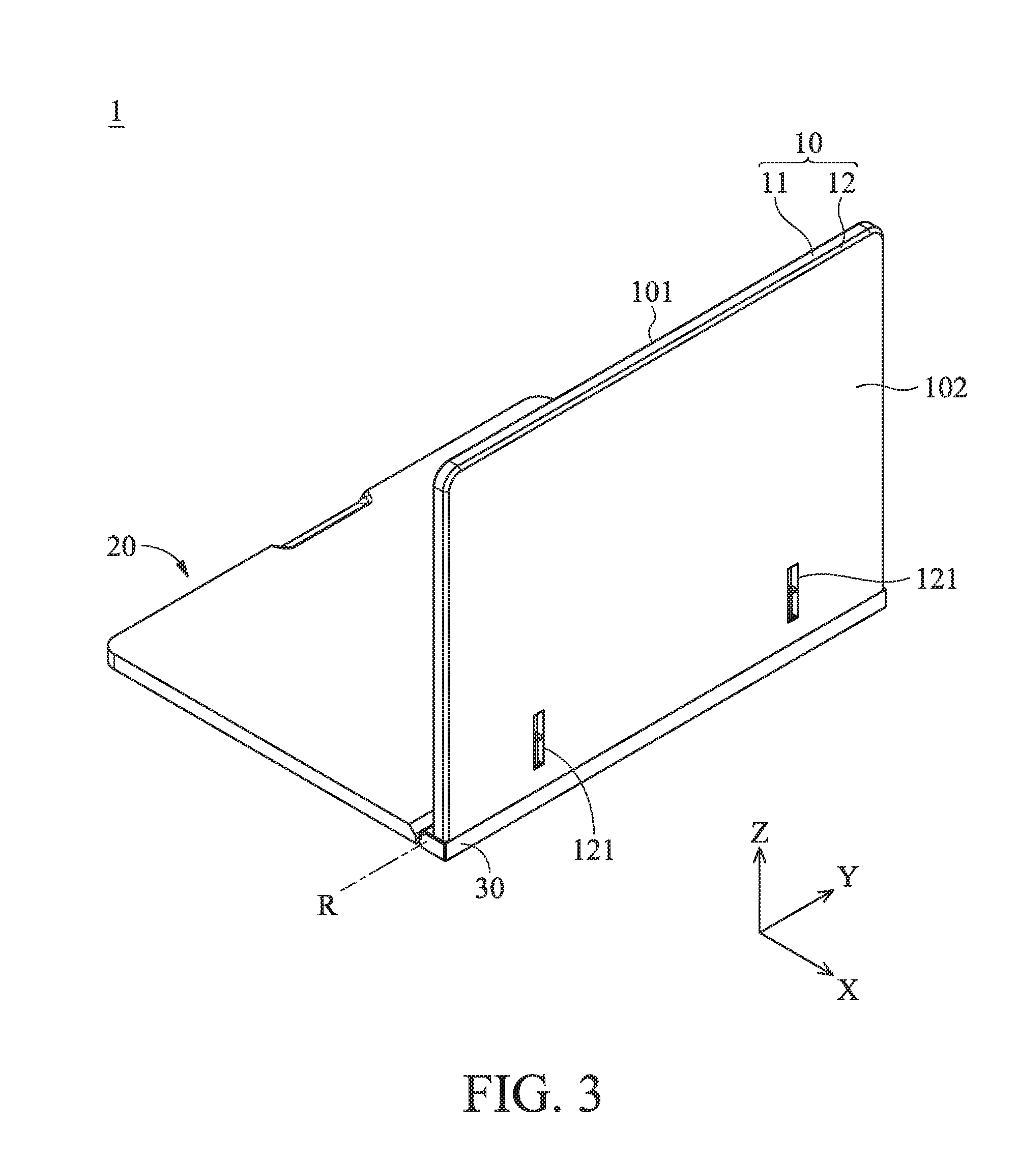
[0018] FIG. 3 is a schematic diagram of the portable electronic device in FIG. 1 after assembly.
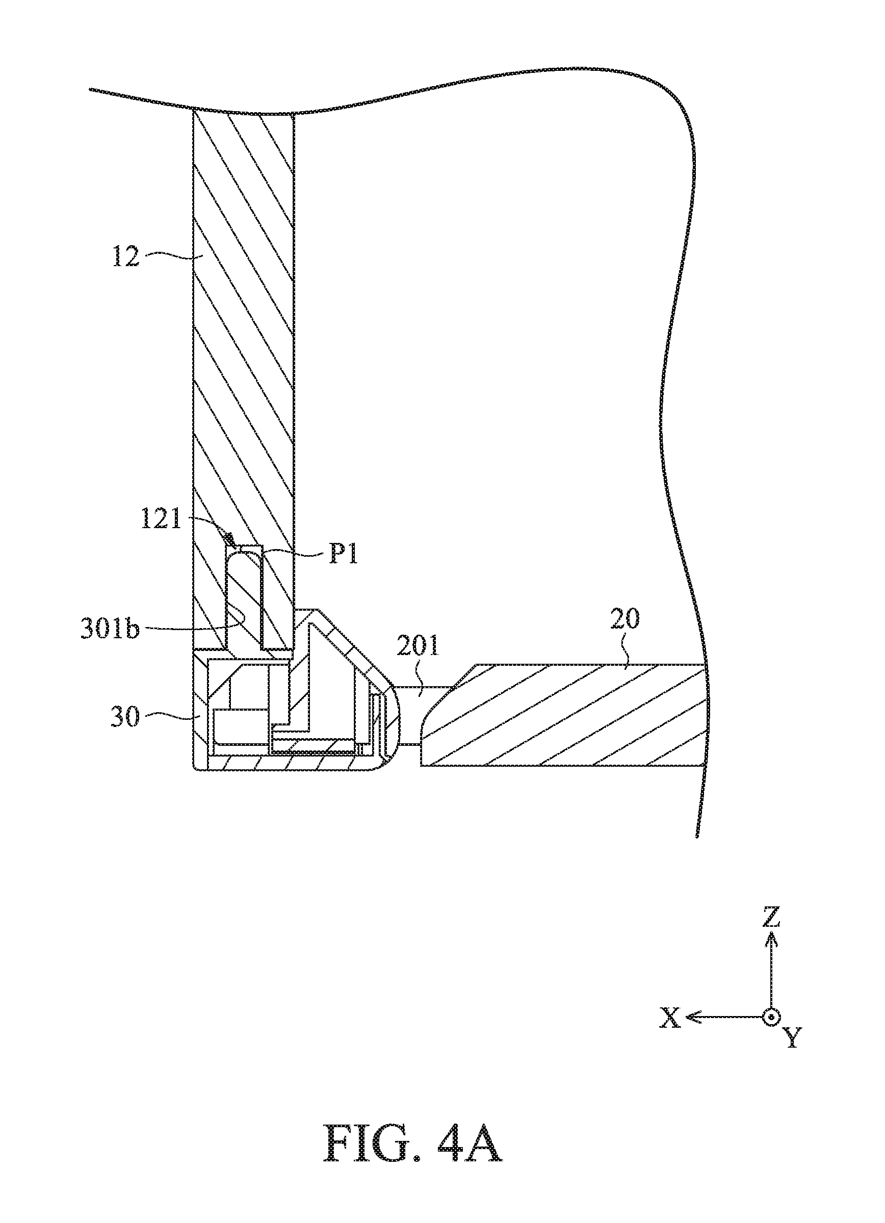
[0019] FIG. 4A is a cross-sectional view diagram of the slot and the vertical surface structure in FIG. 3 after assembly.
[0020] FIG. 4B is a cross-sectional view diagram of the slot, the connecting assembly and the first slope structure in FIG. 3 after assembly.
DETAILED DESCRIPTION OF INVENTION
[0021] The making and using of the embodiments of the portable electronic devices are discussed in detail below. The embodiments of the present invention will be described with reference to the drawings. It should be appreciated, however, that the embodiments provide many applicable inventive concepts that can be embodied in a wide variety of specific contexts. The specific embodiments discussed are merely illustrative of specific ways to make and use the embodiments, and do not limit the scope of the disclosure.
[0022] Unless defined otherwise, all technical and scientific terms used herein have the same meaning as commonly understood to one of ordinary skill in the art to which this invention belongs. It should be appreciated that each term, which is defined in a commonly used dictionary, should be interpreted as having a meaning conforming to the relative skills and the background or the context of the present disclosure, and should not be interpreted by an idealized or overly formal manner unless defined otherwise. In addition, directional terms such as up, down, left, right, front, back and the like mentioned in the following embodiments are only directions with reference to the attached drawings. The directional terms used are intended to illustrate and not to limit the present invention.
[0023] Referring to FIG. 1, a portable electronic device 1 is provided according to an embodiment of the present invention. The portable electronic device 1, for example, may be a laptop computer, primarily comprises a display unit 10, an input unit 20, and a hinge member 30. The display unit 10 may has a flat structure and configured to displaying images. In some embodiments, the display unit 10 may be a touch display. The display unit 10 includes a display panel 11 and a frame body 12 which are connected each other. The display unit has a front side 101 and a rear side 102, wherein the display panel 11 is located on the front side 101 and the frame body 12 is located on the rear side 102, wherein the rear side 102 is opposite to the front side 101. In the present embodiment, the display unit 10 may be a tablet, and the display panel 11 thereof may be a touch display panel and is cable of showing images or texts on the front side 101. As shown in FIGS. 1 and 3, the frame body 12 has at least a slot 121, and the slot 121 and the guide pin 301 of the hinge member 30 are detachably connected.
[0024] The input unit 20 may be a flat structure, and the surface thereof may be equipped with a keyboard or a touch panel (not shown). The inside of the input unit 20 may further include different electronic components (not shown) such as a CPU, a memory or an input unit board. As shown in FIG. 1, the input unit 20 has at least a protrusion 201 configured to be pivotally connected to the hinge member 30. In some embodiments, various electronic components such as a CPU, a memory, and an input unit board may also be disposed inside the display unit 10.
[0025] The hinge member 20 has at least a guide pin 301 and at least a recess 302. In the present embodiment, the hinge member 30 has two guide pins 301 respectively corresponding to the two slots 121 of the frame body 12. In addition, the hinge member 30 further has two recesses 302 configured to receive the two protrusions 201 of the input unit 20, respectively.
[0026] Please continue refer to FIG. 1, the portable electronic device 1 further comprises at least a connecting assembly 13. In the present embodiment, the portable electronic device 1 comprises two connecting assemblies 13 which are received in the two slots 121 of the frame body 12, respectively. Particularly, the connecting assembly 131 includes a sliding member 131 and a spring 132. The spring 132 is disposed around (or envelops) the sliding member 131.
[0027] Referring to FIG. 3, which is a schematic diagram of the portable electronic device 1 in FIG. 1 after assembly. The display unit 10 is connected to the guide pin 301 of the hinge member 30 via the slot 121 and the connecting assembly 13. Therefore, by the hinge assembly 30, the display unit 10 is can be rotated relative to the display unit 20 around a rotary axis R, and the display unit 10 can be detachably connected the hinge member 30 so that the usage mode of the portable electronic device 1 can be switched, such as the notebook mode or the tablet mode, according to the user's requirements.
[0028] Next, please refer to FIG. 2A, which is an enlarged view of the guide pin 301 in FIG. 1. As can be seen from FIG. 2A, the guide pin 301 has a first slope structure 301a and a vertical surface structure 301b. The first slope structure 301a and the vertical surface structure 301b are arranged in a direction that is parallel to the rotary axis R (Y-axis direction). In particular, an acute angle .alpha. is between the first slope structure 301a and the vertical surface structure 301b, and the length L1 of the first slope structure 301a in the Y-axis direction is less than or equal to half of the length L of the guide pin 301 in the Y-axis direction. In some embodiments, the ratio of the length L1 of the first slope structure 301a to the length L of the guide pin 301 is greater than 0 (zero) and less than or equal to 1/3 (one-third). By using the aforementioned structural design, the structural strength of the guide pin 301 can be maintained even when the display unit 10 and the hinge member 30 are assembled.
[0029] Please refer to FIG. 2B, which is a schematic perspective view of the connecting assembly 13 of FIG. 1 after assembled. As shown in FIG. 2B, the sliding member 131 has a main body 131a and a rod portion 13 lb. The spring 132 is disposed around the rod portion 131b. The main body 131a has a second slope structure S1. When the display unit 10 and the hinge member 30 assemble, the second slope structure S1 is in contact with the first slope structure 301a. That is, the first slope structure 301a and the second slope structure S1 have substantially the same degree of slope with respect to the vertical direction (Z-axis direction). In addition, the main body 131a further has a top surface structure S2 and a connecting surface structure S3. The top surface structure S2 is connected to the rod portion 131b, and the connecting surface structure S3 connects the second slope structure S1 and the top surface structure S2. By this structural design, the assembly positioning can be enhanced and the position of the sliding member 131 can be adjusted by the elastic force produced from the spring 132, to ensure that the first slope structure 301a and the second slope structure S1 can be in close contact when they are combined, thereby the situation of the connection gap being too large can be avoided.
[0030] Please refer to FIG. 4A. FIG. 4A is a schematic cross-sectional view of the slot 121 and the vertical surface structure 301b in FIG. 3. The slot 121 of the frame body 12 has a first portion P1 corresponding to the vertical surface structure 301b of the guide pin 131, and the first portion P1 can receive the vertical surface structure 301b.
[0031] Please refer to FIG. 4B, which is a schematic cross-sectional view of the slot 121, the connecting assembly 13 and the first slope structure 301a in FIG. 3. The slot 121 of the frame body 12 has a second portion P2 corresponding to the first slope structure 301a of the guide pin 301, wherein the connecting assembly 13 is disposed in the second portion P2, and the sliding member 131 is slidable within the second portion P2. The first portion P1 and the second portion P2 of the slot 121 are communicated with each other, and they are arranged along the direction that is parallel rotary axis R (Y-axis direction), and the positions of the first portion P1 and the second portion P2 respectively correspond to the vertical surface structure 301b and the first inclined surface structure 301a. Furthermore, for receiving the connecting assembly 13, the depth of the second portion P2 in the vertical direction (Z-axis direction) is greater than the depth of the first portion P1 in the vertical direction (Z-axis direction).
[0032] In the portable electronic device of the above embodiment of the present invention, the sliding member 131 is disposed on the display unit 10 and a corresponding first slope structure 301a is formed on the guide pin 301 of the hinge member 30, so that the problem, the touch display screen is easily shaken or the connection strength is insufficient when the screen is connected with the connecting mechanism, can be effectively solved. In addition, using the portable electronic device of the above embodiments of the present invention can improve the positioning effect of the assembly and an excessive connection gap between thee display unit and the hinge member can be avoided.
[0033] Use of ordinal terms such as "first", "second", "third", etc., in the claims to modify a claim element does not by itself connote any priority, precedence, or order of one claim element over another or the temporal order in which acts of a method are performed, but are used merely as labels to distinguish one claim element having a certain name from another element having the same name (but for use of the ordinal term) to distinguish the claim elements.
[0034] It will be apparent to those skilled in the art that various modifications and variations can be made in the invention. It is intended that the standard and examples be considered as exemplary only, with a true scope of the disclosed embodiments being indicated by the following claims and their equivalents.
* * * * *
D00000
D00001
D00002
D00003
D00004
D00005
XML
uspto.report is an independent third-party trademark research tool that is not affiliated, endorsed, or sponsored by the United States Patent and Trademark Office (USPTO) or any other governmental organization. The information provided by uspto.report is based on publicly available data at the time of writing and is intended for informational purposes only.
While we strive to provide accurate and up-to-date information, we do not guarantee the accuracy, completeness, reliability, or suitability of the information displayed on this site. The use of this site is at your own risk. Any reliance you place on such information is therefore strictly at your own risk.
All official trademark data, including owner information, should be verified by visiting the official USPTO website at www.uspto.gov. This site is not intended to replace professional legal advice and should not be used as a substitute for consulting with a legal professional who is knowledgeable about trademark law.