Primer Cup for a Primer Having Deposited Ignitable Material
Mohler; Timothy ; et al.
U.S. patent application number 16/175589 was filed with the patent office on 2019-05-02 for primer cup for a primer having deposited ignitable material. This patent application is currently assigned to Spectre Enterprises, Inc.. The applicant listed for this patent is Spectre Enterprises, Inc.. Invention is credited to Timothy Mohler, Daniel Yates.
| Application Number | 20190128656 16/175589 |
| Document ID | / |
| Family ID | 66245455 |
| Filed Date | 2019-05-02 |
| United States Patent Application | 20190128656 |
| Kind Code | A1 |
| Mohler; Timothy ; et al. | May 2, 2019 |
Primer Cup for a Primer Having Deposited Ignitable Material
Abstract
A cup for a primer facilitates the use of deposited ignitable material, for example, a layered thermite material, within a cup that fits within a standard primer pocket within a firearm cartridge casing or other location designed for a presently available primer. The primer cup includes a tube and a disk. The ignitable material can be deposited on one surface of the disk. The disk can then be inserted within the tube, wherein it is retained within the tube by an inwardly projecting ledge at one end of the tube.
| Inventors: | Mohler; Timothy; (Vero Beach, FL) ; Yates; Daniel; (Melbourne, FL) | ||||||||||
| Applicant: |
|
||||||||||
|---|---|---|---|---|---|---|---|---|---|---|---|
| Assignee: | Spectre Enterprises, Inc. Melbourne FL |
||||||||||
| Family ID: | 66245455 | ||||||||||
| Appl. No.: | 16/175589 | ||||||||||
| Filed: | October 30, 2018 |
Related U.S. Patent Documents
| Application Number | Filing Date | Patent Number | ||
|---|---|---|---|---|
| 62579141 | Oct 30, 2017 | |||
| Current U.S. Class: | 1/1 |
| Current CPC Class: | F42C 19/083 20130101; F42C 19/10 20130101 |
| International Class: | F42C 19/10 20060101 F42C019/10; F42C 19/08 20060101 F42C019/08 |
Claims
1. A primer, comprising: a tube having a side wall, the tube defining a first open end, a second open end, a tube interior, and a central axis, the second open end defining a ledge projecting towards the central axis; a disk having a first surface, a second surface, and an edge, the disk being dimensioned and configured to fit within the interior of the tube with the periphery of the disk abutting the wall, the disk having an ignitable material deposited upon the first surface; and the ledge being dimensioned and configured to resist passage of the disk therethrough.
2. The primer according to claim 1, wherein: the tube is generally cylindrical, the tube defining an internal diameter; and the disk is generally circular, the disk having a diameter that substantially matches the internal diameter of the tube.
3. The primer according to claim 2, wherein the ledge extends around substantially the entire wall, the ledge defining the second open end.
4. The primer according to claim 3, wherein the edge of the disk includes a first edge portion adjacent to the first surface, and a second edge portion adjacent to the second surface, the second edge portion having a diameter corresponding to a diameter of the second open end, the disk defining a lip extending between the first edge portion and the second edge portion, the first edge portion defining a first thickness, the second edge portion defining a second thickness, the thickness of the second edge portion being substantially equal to a thickness of the ledge of the tube, the lip of the disk having a width that is substantially equal to the width of the ledge of the tube.
5. The primer according to claim 4, wherein the wall defines a plurality of inwardly extending projections, each of the inwardly extending projections being disposed a distance above the ledge that is substantially equal to the thickness of the first edge portion, whereby the disk is retained between the ledge and the inwardly extending projections.
6. The primer according to claim 1, wherein the wall defines a plurality of inwardly extending projections, each of the inwardly extending projections being disposed a distance above the ledge that is substantially equal to a thickness of a portion of the edge of the disk abutting the wall, whereby the disk is retained between the ledge and the inwardly extending projections.
7. The primer according to claim 1, wherein the ledge extends around substantially the entire wall, the ledge defining the second open end.
8. The primer according to claim 7, wherein the edge of the disk includes a first edge portion adjacent to the first surface, and a second edge portion adjacent to the second surface, the second edge portion being dimensioned and configured to substantially fill the second open end, the disk defining a lip extending between the first edge portion and the second edge portion, the first edge portion defining a first thickness, the second edge portion defining a second thickness, the thickness of the second edge portion being substantially equal to a thickness of the ledge of the tube, the lip of the disk having a width that is substantially equal to the width of the ledge of the tube.
9. The primer according to claim 8, wherein the wall defines a plurality of inwardly extending projections, each of the inwardly extending projections being disposed a distance above the ledge that is substantially equal to the thickness of the first edge portion, whereby the disk is retained between the ledge and the inwardly extending projections.
10. The primer according to claim 1, wherein: the first surface includes a recess defined therein; and the ignitable material is deposited within the recess.
11. The primer according to claim 1, wherein the ignitable material includes alternating layers of reducing metal and metal oxide.
12. The primer according to claim 11, wherein the ignitable material further has interface layers of reducing metal oxide between the reducing metal layers and metal oxide layers, the reducing metal oxide having a thickness of less than 1 nm.
13. A cup for a primer, the cup comprising: a tube having a side wall, the tube defining a first open end, a second open end, a tube interior, and a central axis, the second open end defining a ledge projecting towards the central axis; a disk having a first surface, a second surface, and an edge, the disk being dimensioned and configured to fit within the interior of the tube with the periphery of the disk abutting the wall; and the ledge being dimensioned and configured to resist passage of the disk therethrough.
14. The cup according to claim 13, wherein: the tube is generally cylindrical, the tube defining an internal diameter; and the disk is generally circular, the disk having a diameter that substantially matches the internal diameter of the tube.
15. The cup according to claim 14, wherein the ledge extends around substantially the entire wall, the ledge defining the second open end.
16. The cup according to claim 15, wherein the edge of the disk includes a first edge portion adjacent to the first surface, and a second edge portion adjacent to the second surface, the second edge portion having a diameter corresponding to a diameter of the second open end, the disk defining a lip extending between the first edge portion and the second edge portion, the first edge portion defining a first thickness, the second edge portion defining a second thickness, the thickness of the second edge portion being substantially equal to a thickness of the ledge of the tube, the lip of the disk having a width that is substantially equal to the width of the ledge of the tube.
17. The cup according to claim 16, wherein the wall defines a plurality of inwardly extending projections, each of the inwardly extending projections being disposed a distance above the ledge that is substantially equal to the thickness of the first edge portion, whereby the disk is retained between the ledge and the inwardly extending projections.
18. The cup according to claim 13, wherein the wall defines a plurality of inwardly extending projections, each of the inwardly extending projections being disposed a distance above the ledge that is substantially equal to a thickness of a portion of the edge of the disk abutting the wall, whereby the disk is retained between the ledge and the inwardly extending projections.
19. The cup according to claim 13, wherein the ledge extends around substantially the entire wall, the ledge defining the second open end.
20. The cup according to claim 19, wherein the edge of the disk includes a first edge portion adjacent to the first surface, and a second edge portion adjacent to the second surface, the second edge portion being dimensioned and configured to substantially fill the second open end, the disk defining a lip extending between the first edge portion and the second edge portion, the first edge portion defining a first thickness, the second edge portion defining a second thickness, the thickness of the second edge portion being substantially equal to a thickness of the ledge of the tube, the lip of the disk having a width that is substantially equal to the width of the ledge of the tube.
21. The primer according to claim 20, wherein the wall defines a plurality of inwardly extending projections, each of the inwardly extending projections being disposed a distance above the ledge that is substantially equal to the thickness of the first edge portion, whereby the disk is retained between the ledge and the inwardly extending projections.
Description
CROSS REFERENCE TO RELATED APPLICATION
[0001] This application claims the benefit of U.S. provisional patent application Ser. No. 62/579,141, filed Oct. 30, 2017, and entitled "Primer Cup for a Thermite Primer."
TECHNICAL FIELD
[0002] The present invention relates to primers for firearms and other munitions. More specifically, a cup is provided for containing the ignitable material of a primer, and for holding the ignitable material within a firearm cartridge or within another munition.
BACKGROUND INFORMATION
[0003] Cartridges for firearms, as well as other munitions such as larger projectile cartridges and explosives are often ignited by a primer. Presently available primers and detonators are made from a copper or brass alloy cup with a brass anvil and containing lead azide or lead styphnate. When the base of the cup is struck by a firing pin, the priming compound is crushed between the cup's base and the anvil, igniting the primer charge. The burning primer then ignites another flammable substance such as smokeless powder, explosive substances, etc. Lead azide and lead styphnate are hazardous due to their toxicity as well as their highly explosive nature. Additionally, present manufacturing methods are very labor-intensive, with the necessary manual processes raising costs, causing greater difficulty in maintaining quality control.
[0004] Energetic materials such as thermite are presently used when highly exothermic reactions are needed. Uses include cutting, welding, purification of metal ores, and enhancing the effects of high explosives. A thermite reaction occurs between a metal oxide and a reducing metal. Examples of metal oxides include La.sub.2O.sub.3, AgO, ThO.sub.2, SrO, ZrO.sub.2, UO.sub.2, BaO, CeO.sub.2, B.sub.2O.sub.3, SiO.sub.2, V.sub.2O.sub.5, Ta.sub.2O.sub.5, NiO, Ni.sub.2O.sub.3, Cr.sub.2O.sub.3, MoO.sub.3, P.sub.2O.sub.5, SnO.sub.2, WO.sub.2, WO.sub.3, Fe.sub.3O.sub.4, COO, Co.sub.3O.sub.4, Sb.sub.2O.sub.3, PbO, Fe.sub.2O.sub.3, Bi.sub.2O.sub.3, MnO.sub.2, Cu.sub.2O, and CuO. Example reducing metals include Al, Zr, Th, Ca, Mg, U, B, Ce, Be, Ti, Ta, Hf, and La. The reducing metal may also be in the form of an alloy or intermetallic compound of the above-listed metals.
[0005] A properly designed energetic material, for example, that which is disclosed in US 2016/0102030, which was invented by K. R. Coffey et al. and published on Apr. 14, 2016, would provide an effective alternative to presently used primer materials, as well as being safer to manufacture. The entire disclosure of US 2016/0102030 is expressly incorporated herein by reference. In addition to the structures and methods disclosed therein, a primer cup is disclosed herein for easily installing such a primer within a conventional cartridge casing, or within another location that is designed to receive a conventional primer.
SUMMARY
[0006] The above-described needs are met by a primer. The primer comprises a tube having a side wall. The tube defines a first open end, a second open end, a tube interior, and a central axis. The second open end defines a ledge projecting towards the central axis. The primer further comprises a disk having a first surface, a second surface, and an edge. The disk is dimensioned and configured to fit within the interior of the tube with the periphery of the disk abutting the wall. The disk has an ignitable material deposited upon the first surface. The ledge of the tube is dimensioned and configured to resist passage of the disk therethrough.
[0007] The above-described needs are met by a cup for a primer. The cup comprises a tube having a side wall. The tube defines a first open end, a second open end, a tube interior, and a central axis. The second open end defines a ledge projecting towards the central axis. The primer further comprises a disk having a first surface, a second surface, and an edge. The disk is dimensioned and configured to fit within the interior of the tube with the periphery of the disk abutting the wall. The ledge of the tube is dimensioned and configured to resist passage of the disk therethrough.
[0008] These and other aspects of the invention will become more apparent through the following description and drawings.
BRIEF DESCRIPTION OF THE DRAWINGS
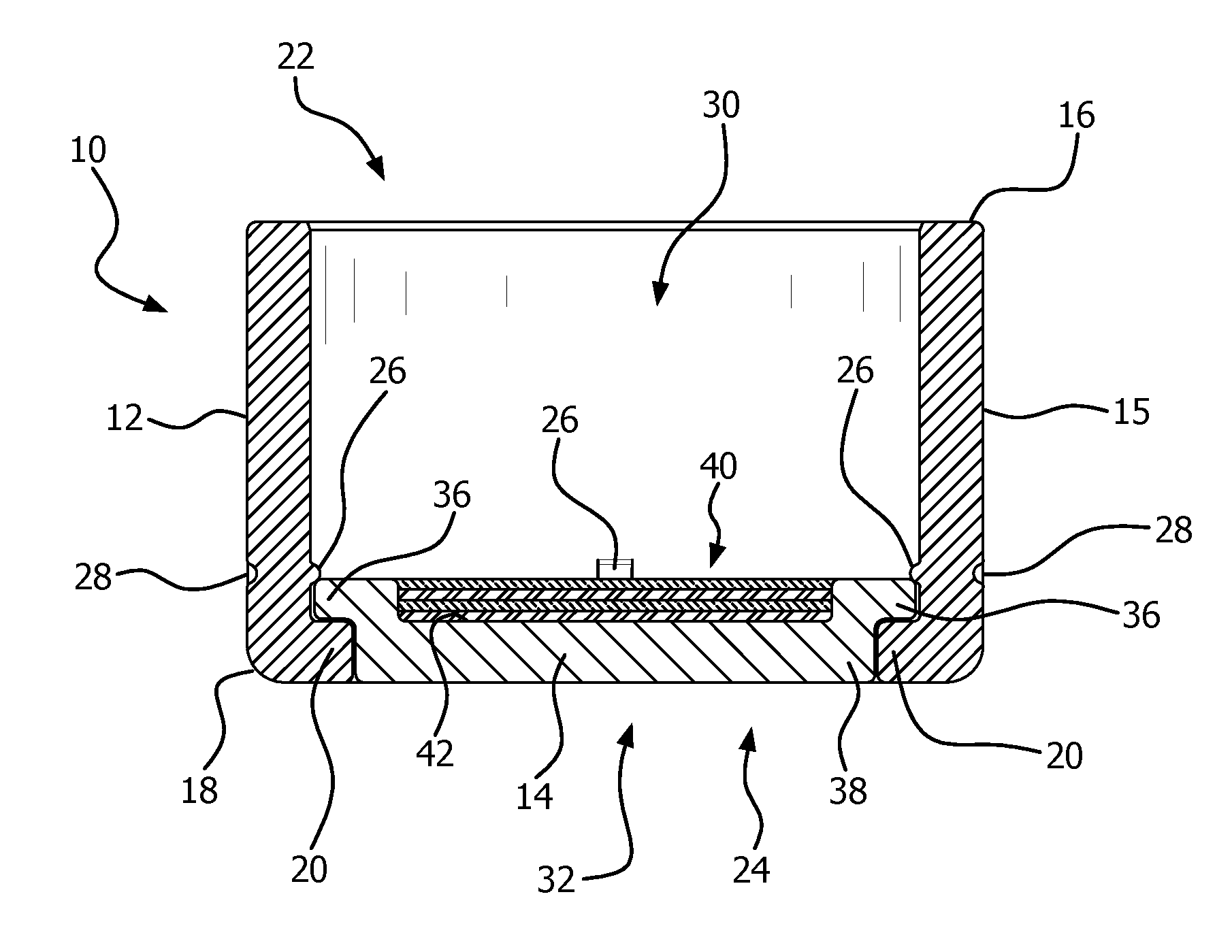
[0009] FIG. 1 is a cross sectional view of a primer.
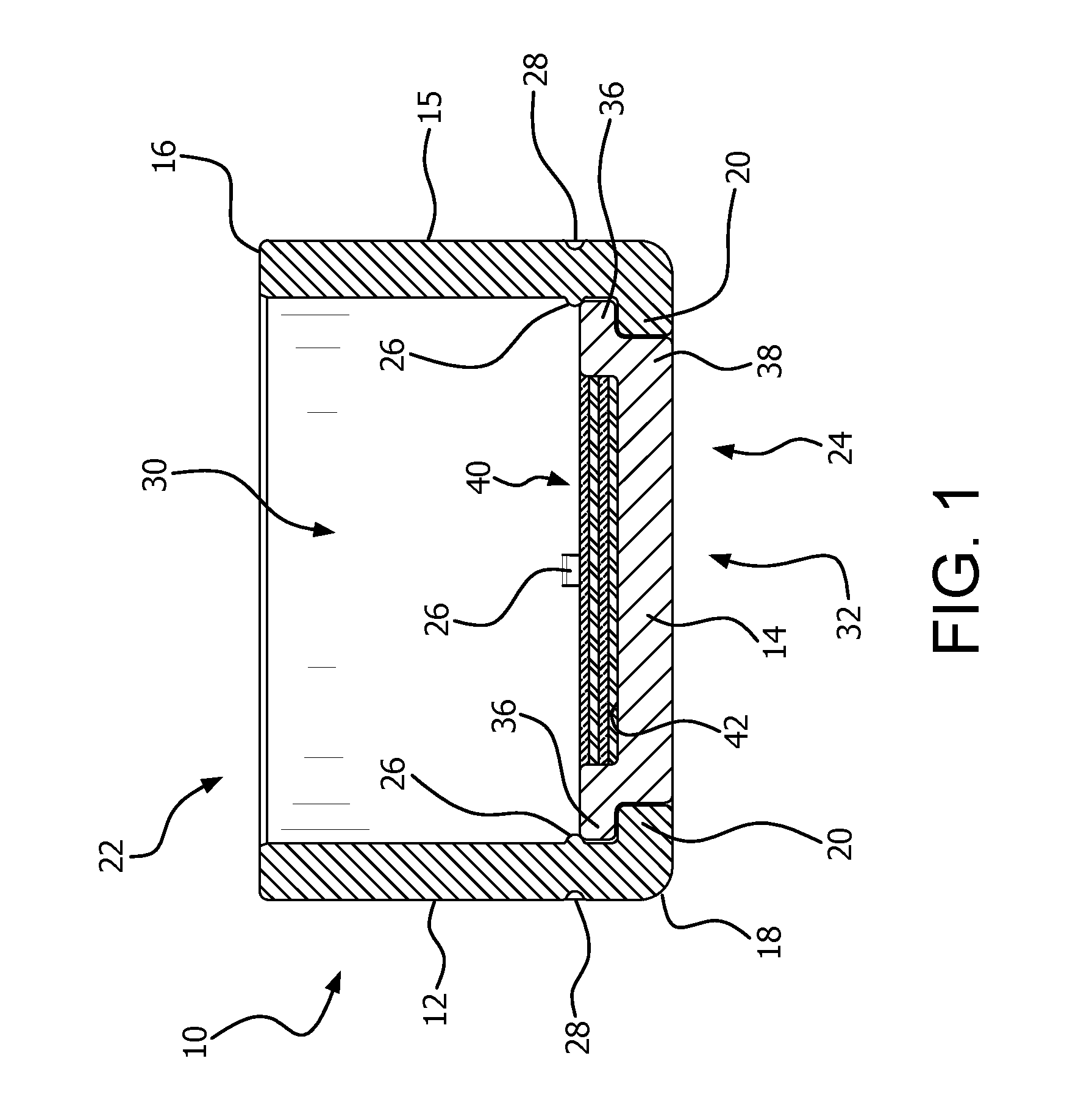
[0010] FIG. 2 is a side elevational view of a tube for a primer cup.
[0011] FIG. 3 is a cross-sectional view of the tube for a primer cup of FIG. 2, taken along the lines A-A in FIG. 1.
[0012] FIG. 4 is a top plan view of a tube for a primer cup of FIG. 2.
[0013] FIG. 5 is a perspective view of a tube for a primer cup of FIG. 2.
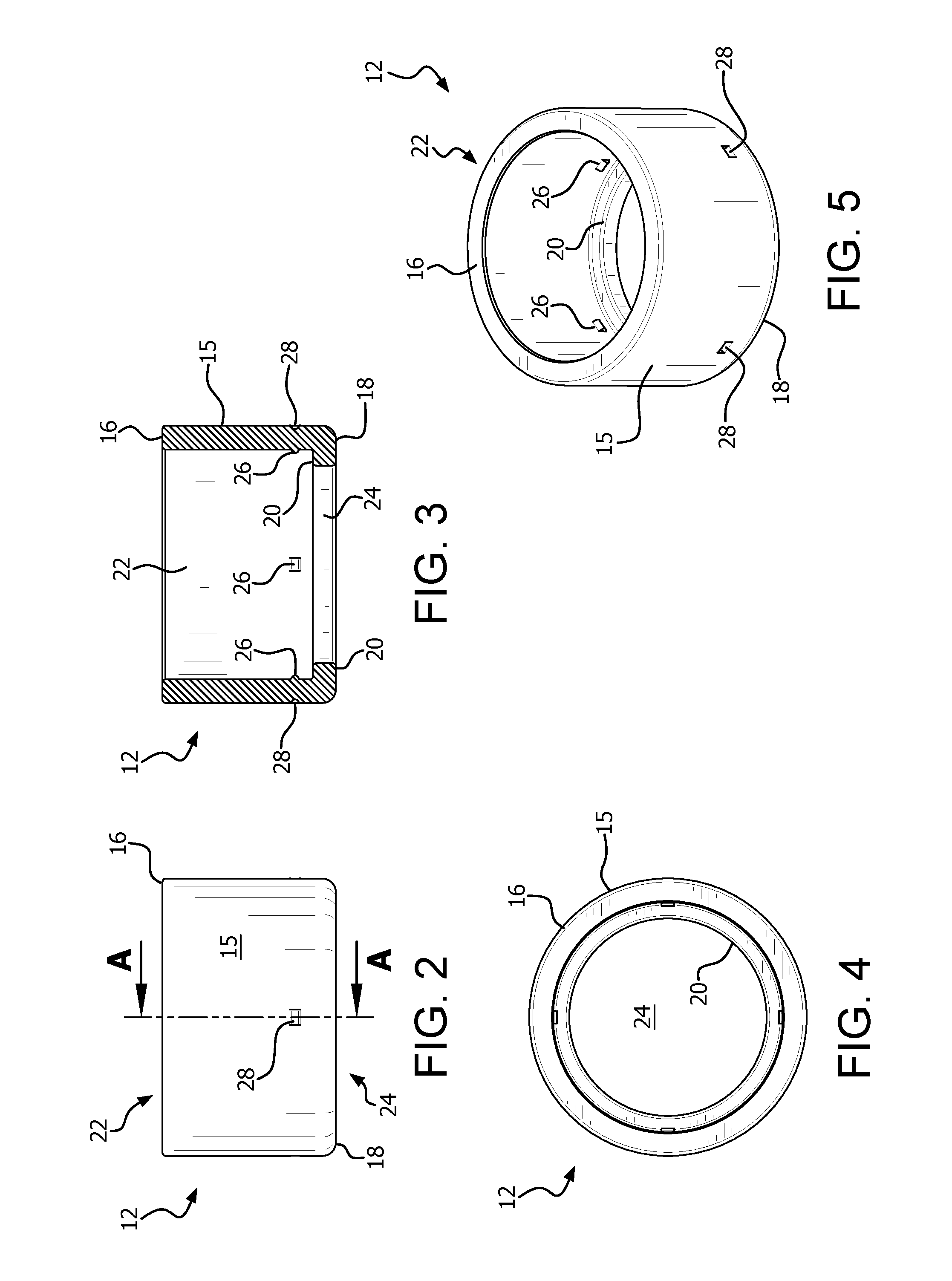
[0014] FIG. 6 is a top plan view of a disk for a primer cup.
[0015] FIG. 7 is a cross-sectional view of the disk for a primer cup of FIG. 6, taken along the lines B-B in FIG. 5.
[0016] FIG. 8 is a side elevational view of a disk for a primer cup of FIG. 6.
[0017] FIG. 9 is a perspective view of a disk for a primer cup of FIG. 6.
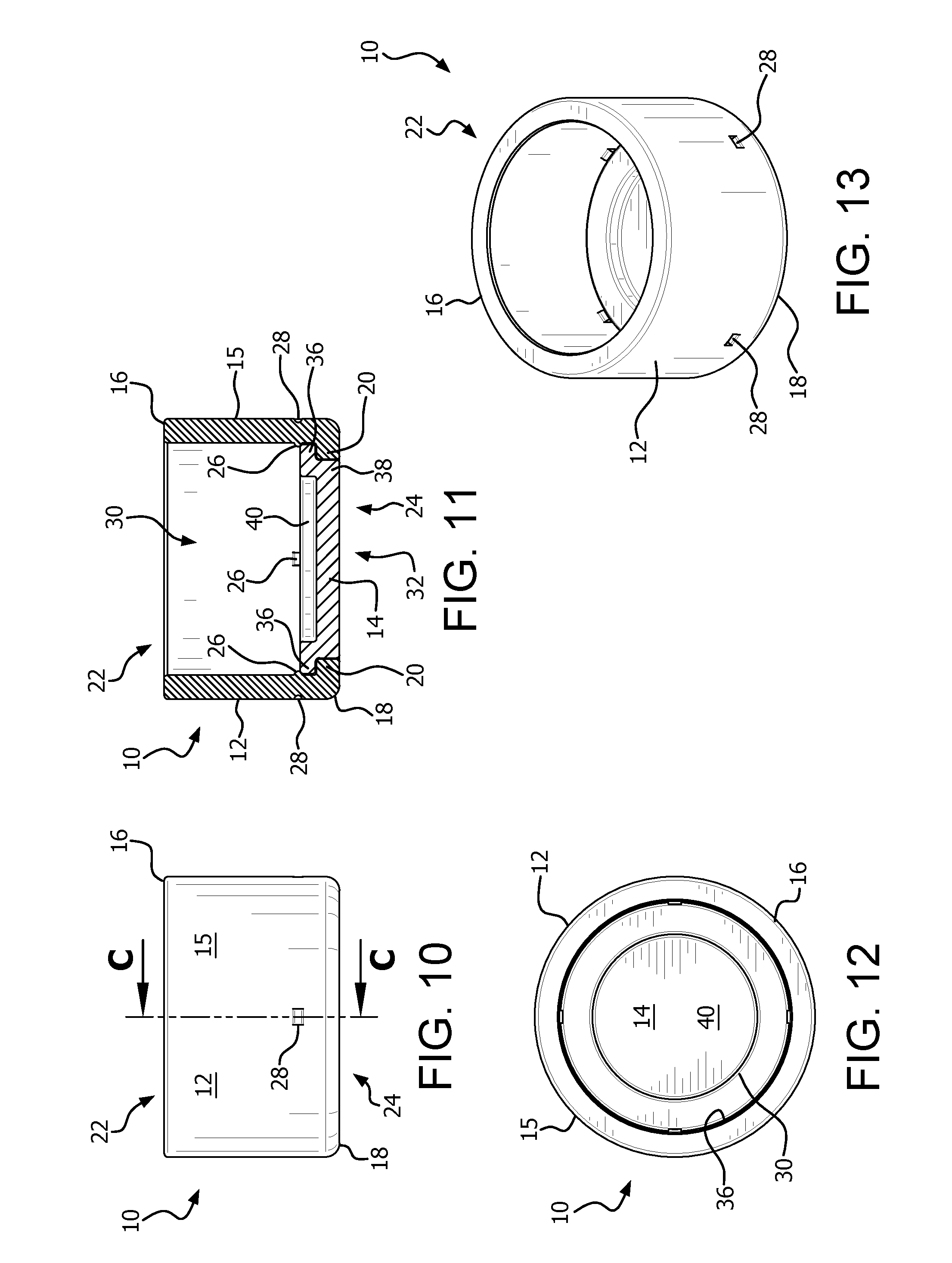
[0018] FIG. 10 is a side elevational view of a primer cup utilizing a tube of FIG. 2 and a disk of FIG. 5.
[0019] FIG. 11 is a cross-sectional view of the primer cup of FIG. 10, taken along the lines C-C in FIG. 9.
[0020] FIG. 12 is a top plan view of a primer cup of FIG. 10.
[0021] FIG. 13 is a perspective view of a primer cup of FIG. 10.
[0022] Like reference characters denote like elements throughout the drawings.
DETAILED DESCRIPTION
[0023] Referring to the drawings, an example of a primer cup is shown. The illustrated example of a primer cup may be used with a firearm cartridge, or with another munition that utilizes a primer in any capacity. Although the illustrated example of a primer cup is intended for use with an ignitable material that can be deposited on the disk as described below, for example, a thermite priming material, it is not limited to such use. As used herein, the terms top, bottom, front, back, side, etc. are used for convenience only, and are not intended to limit the scope of the invention. It is recognized that rotation of the components described herein would result in a different portion of each component being a top, side, etc.
[0024] The primer cup 10 (FIGS. 1 and 10-13) includes a tube 12 (FIGS. 2-5) and a disk 14 (FIGS. 6-9). The tube 12 and disk 14 are formed from a malleable metal, for example, brass, soft steel, or other malleable metals. The illustrated example is made from brass. The illustrated example of the tube 12 is generally cylindrical, and the illustrated example of the disk 14 is generally circular. As used herein, generally cylindrical is defined as sufficiently cylindrical to fit within a presently used primer pocket. Other shapes may be used to conform to other primer pockets without departing from the invention.
[0025] Referring to FIGS. 2-5, the tube 12 includes a side wall 15 having a first edge 16 and a second edge 18. The first edge 16 is substantially straight, so that it may conform to the shape of a typical primer pocket. The second edge 18 includes an inwardly projecting ledge 20 extending about the interior circumference of the side wall 15. A first opening 22 is defined at the first edge 16 of the tube 12, and extends between the sidewalls 15. A second opening 24 is disposed within the ledge 20. In the illustrated example, the openings 22, 24 are generally centrally located with respect to the sidewall 15. The side wall 15 further includes at least one inward projection 26 disposed a short distance inward from the ledge 20. The illustrated example of a tube 14 includes four inward projections 26, which in the illustrated example are formed as a result of a crimp 28 corresponding to each of the inward projections 26.
[0026] Referring to FIGS. 6-9, the disk 14 includes a first face 30, a second face 32, and a peripheral edge 34. The peripheral edge 34 includes a first portion 36 adjacent to the face 30, and a second portion 38 adjacent to the face 32. The edge portion 36 has a larger diameter than the edge portion 38, resulting in a circumferential lip 39 being defined by the difference in diameter between the edge portion 36 and edge portion 38. In the illustrated example, the edge portion 36 has an exterior diameter that corresponds to the internal diameter of the sidewall 15 of the tube 12. The edge portion 38 has an exterior diameter that substantially corresponds to the internal diameter of the opening 24. The thickness of the edge portion 36 corresponds to the distance between the ledge 20 and projections 26. The thickness of the edge portion 38 corresponds to the thickness of the ledge 20. As used herein, the substantially corresponding dimensions are sufficiently close so that the disk 14 can be retained within the tube 12 as described below. The first face 30 of the disk 14 also includes a recessed portion 40. In the illustrated example, the recessed portion 40 has a diameter that is smaller than the diameter of the second edge portion 38, and is generally centrally located within the first face 36. In the illustrated example, the difference between the diameter of the recess 40 and the diameter of the second edge 38 does not substantially exceed twice the thickness of the disk 14. The recessed portion 40 also has a depth that does not substantially exceed half of the thickness of the disk 14. The recess 14 contains an ignitable material that has been deposited thereon, and one examples of the recess 14 is filled with thermite (FIG. 1 shows thermite 42 or other ignitable material 42 in the recess 40). An example of a suitable thermite may be prepared according to U.S. patent application Ser. No. 14/850,902, which was filed by Kevin R. Coffey et al. on Sep. 10, 2015, and published as US 2016/0102030 on Apr. 14, 2016, the entire disclosure of which is expressly incorporated herein by reference.
[0027] An example of a process for making the tube 12 begins with malleable metal tubing such as brass tubing having an external diameter corresponding to a typical external diameter for a standard primer. The tube is cut to a length corresponding to or slightly longer than the length of a standard primer. One end of the tube is bent to form the ledge 20. The sidewall 15 of the tube 12 is then crimped to form the inward projections 26.
[0028] The disk 14 is made from a sheet of malleable metal, such as a brass sheet. Some examples of the process will form multiple disks 14 simultaneously. A press is utilized to form the disk 14 into the shape that is described above and illustrated in the drawings. Individual discs 14 can be cut from the sheet before or after the pressing process. The thermite may be deposited within the recess 40 either before or after the discs 14 are cut from the brass sheet, depending upon when the pressing process takes place.
[0029] Once the disks 14 and tubes 12 are formed, a disk 14 is inserted into the opening 22 of a tube 12, and moved downward within the tube 12 until the second edge portion 38 is within the opening 24, and the first edge portion 36 abuts the ledge 20, and is retained by the inward projections 26. Once the disks 14 are installed within the corresponding tubes 12, an adhesive may be utilized to further secure each disk 14 within its tube 12. Suitable adhesives are known in the art of manufacturing ammunition for firearms. As one example, an anaerobic, UV curable adhesive is known to be drawn into the interface between a conventional primer and casing, and could also be utilized to adhere the disk within 14 to the tube 12. The inward projections 26 may be formed either before or after the disk 14 is positioned inside the tube 12.
[0030] The present invention therefore provides a primer that includes an ignitable material deposited thereon. The ignitable material can in some examples be a layered thermite material. The primer can be easily and safely manufactured by depositing the ignitable material on a disk, and then inserting the disk into a tube to form the primer cup. The primer can be dimensioned and configured to fit within a primer pocket of a standard firearm cartridge or the primer pocket of another munition that utilizes standard primers.
[0031] A variety of modifications to the above-described embodiments will be apparent to those skilled in the art from this disclosure. Thus, the invention may be embodied in other specific forms without departing from the spirit or essential attributes thereof. The particular embodiments disclosed are meant to be illustrative only and not limiting as to the scope of the invention. The appended claims, rather than to the foregoing specification, should be referenced to indicate the scope of the invention.
* * * * *
D00000
D00001
D00002
D00003
D00004
XML
uspto.report is an independent third-party trademark research tool that is not affiliated, endorsed, or sponsored by the United States Patent and Trademark Office (USPTO) or any other governmental organization. The information provided by uspto.report is based on publicly available data at the time of writing and is intended for informational purposes only.
While we strive to provide accurate and up-to-date information, we do not guarantee the accuracy, completeness, reliability, or suitability of the information displayed on this site. The use of this site is at your own risk. Any reliance you place on such information is therefore strictly at your own risk.
All official trademark data, including owner information, should be verified by visiting the official USPTO website at www.uspto.gov. This site is not intended to replace professional legal advice and should not be used as a substitute for consulting with a legal professional who is knowledgeable about trademark law.