Water-Cooled Refrigerated Transport System
Scarcella; Jason D. ; et al.
U.S. patent application number 16/090902 was filed with the patent office on 2019-05-02 for water-cooled refrigerated transport system. This patent application is currently assigned to Carrier Corporation. The applicant listed for this patent is Carrier Corporation. Invention is credited to Thomas J. Benedict, Jason D. Scarcella.
| Application Number | 20190128568 16/090902 |
| Document ID | / |
| Family ID | 58664874 |
| Filed Date | 2019-05-02 |


| United States Patent Application | 20190128568 |
| Kind Code | A1 |
| Scarcella; Jason D. ; et al. | May 2, 2019 |
Water-Cooled Refrigerated Transport System
Abstract
A refrigeration system (30) comprises a compressor (36) for driving the refrigerant along a refrigerant flowpath (34) and having a first stage (36A) and a second stage (36B). A first heat exchanger (38) is along the refrigerant flowpath. An intercooler heat exchanger (120) is along the refrigerant flowpath. A second heat exchanger (42) is along the refrigerant flowpath. An additional heat exchanger (170) is along the refrigerant flowpath between the compressor second stage and the first heat exchanger.
| Inventors: | Scarcella; Jason D.; (Cicero, NY) ; Benedict; Thomas J.; (Syracuse, NY) | ||||||||||
| Applicant: |
|
||||||||||
|---|---|---|---|---|---|---|---|---|---|---|---|
| Assignee: | Carrier Corporation Palm Beach Gardens FL |
||||||||||
| Family ID: | 58664874 | ||||||||||
| Appl. No.: | 16/090902 | ||||||||||
| Filed: | April 24, 2017 | ||||||||||
| PCT Filed: | April 24, 2017 | ||||||||||
| PCT NO: | PCT/US2017/029103 | ||||||||||
| 371 Date: | October 3, 2018 |
Related U.S. Patent Documents
| Application Number | Filing Date | Patent Number | ||
|---|---|---|---|---|
| 62328206 | Apr 27, 2016 | |||
| Current U.S. Class: | 1/1 |
| Current CPC Class: | F25B 2400/13 20130101; F25B 9/008 20130101; F25B 2600/111 20130101; Y02B 30/70 20130101; F25B 6/04 20130101; Y02B 30/743 20130101; F25B 2339/047 20130101 |
| International Class: | F25B 6/04 20060101 F25B006/04; F25B 9/00 20060101 F25B009/00 |
Claims
1. A refrigeration system (30) comprising: a compressor (36) for driving the refrigerant along a refrigerant flowpath (34) having a first stage (36A) and a second stage (36B); a first heat exchanger (38) along the refrigerant flowpath; an intercooler heat exchanger (120) along the refrigerant flowpath, wherein the first heat exchanger and intercooler heat exchanger are tube and fin heat exchangers sharing fins (128); a second heat exchanger (42) along the refrigerant flowpath; and an additional heat exchanger (170) along the refrigerant flowpath between the compressor second stage and the first heat exchanger.
2. The refrigeration system of claim 1 wherein: the additional heat exchanger is a refrigerant-water heat exchanger.
3. The refrigeration system of claim 2 wherein: the system has no other refrigerant-water heat exchanger.
4. The refrigeration system of claim 1 wherein: the additional heat exchanger is a brazed plate heat exchanger.
5. The refrigeration system of claim 1 further comprising: a liquid supply fitting (174) and a liquid return fitting (176) along a liquid flowpath (172) through the additional heat exchanger.
6. The refrigeration system of claim 1 wherein: the system has no water-cooled heat exchanger between the first stage and the second stage.
7. The refrigeration system of claim 1 wherein: the first heat exchanger and intercooler heat exchanger are in series along an air flowpath (508).
8. The refrigeration system of claim 1 further comprising: a first electric fan (50) positioned to drive a first airflow across the first heat exchanger and the intercooler heat exchanger; and a second electric fan (52A, 52B) positioned to drive a second airflow across the second heat exchanger.
9. The refrigeration system of claim 8 being a refrigeration module mountable to an end of an intermodal container.
10. A refrigerated transport system (20) comprising the refrigeration system of claim 1 and wherein: the refrigerated transport system (20) further comprises a body (22) enclosing a refrigerated compartment; the first heat exchanger is positioned to reject heat to an external environment in a first cooling mode; and the second heat exchanger is positioned to absorb heat from the refrigerated compartment in the first cooling mode.
11. The refrigerated transport system of claim 10, further comprising: a controller (64) configured to shut off the first electric fan in response to sufficient sensed water pressure in the additional heat exchanger.
12. The refrigerated transport system of claim 10 wherein the body comprises: a pair of side walls (22C, 22D); a top (22A); a bottom (22B); and one or more doors (28A, 28B).
13. The refrigerated transport system of claim 12, being a refrigerated intermodal shipping container wherein: the one or more doors comprise a pair of hinged doors at a first end of the body; and the refrigeration system is mounted in an equipment box at a second end of the body opposite the first end.
14. A vessel (600) comprising: a hull (606); a plurality of refrigerated intermodal shipping containers according to claim 13 in or on the hull; and a cooled water supply system comprising: one or more heat exchangers (630) positioned to transfer heat between seawater and a heat transfer fluid; and a supply/return system for the heat transfer fluid including one or more pumps (642) for driving a flow of the heat transfer fluid and conduits culminating in respective supply (180) and return (182) conduits coupled to the additional heat exchanger.
15. The vessel of claim 14 wherein: the heat transfer fluid is grey water.
16. A method for operating the refrigeration system of claim 1 the method comprising in a first mode: running the compressor (36) to drive the refrigerant along the refrigerant flowpath (34), the refrigerant passing through the intercooler heat exchanger (120) between the first stage and the second stage; passing the refrigerant through the additional heat exchanger (170) to reject heat from the refrigerant to a fluid flow; passing the refrigerant through the first heat exchanger (38); and passing the refrigerant through the second heat exchanger (42) along the refrigerant flowpath to absorb heat.
17. The method of claim 16 wherein in the first mode: there is no forced airflow across the first heat exchanger and the intercooler heat exchanger.
18. The method of claim 16 wherein: in the first mode: the fluid flow is a water flow.
19. The method of claim 16 further comprising operating in a second mode comprising: running the compressor (36) to drive the refrigerant along the refrigerant flowpath (34), the refrigerant passing through the intercooler heat exchanger (120) between the first stage and the second stage; passing the refrigerant through the additional heat exchanger (170); passing the refrigerant through the first heat exchanger (38) to reject heat; and passing the refrigerant through the second heat exchanger (42) along the refrigerant flowpath to absorb heat.
20. The method of claim 19 wherein: in the second mode: the first mode fluid flow is disabled; and an airflow is driven across the first heat exchanger and the intercooler
Description
CROSS-REFERENCE TO RELATED APPLICATION
[0001] Benefit is claimed of U.S. Patent Application No. 62/328,206, filed Apr. 27, 2016, and entitled "Water-Cooled Refrigerated Transport System", the disclosure of which is incorporated by reference herein in its entirety as if set forth at length.
BACKGROUND
[0002] The disclosure relates to refrigerated transport systems such as intermodal containers. More particularly, the disclosure relates to such refrigerated transport systems having water-cooled modes.
[0003] An exemplary refrigerated intermodal container (also known as a shipping container or intermodal shipping container) has an equipment module at one end of the container. The equipment module contains a vapor compression system having a compressor, a heat rejection heat exchanger downstream of the compressor along a refrigerant flow path, an expansion device, and a heat absorption heat exchanger. One or more first fans may drive an external airflow across the heat rejection heat exchanger. One or more second fans may drive an internal airflow across the heat absorption heat exchanger. In various implementations, for powering the container, there may be a power cord for connecting to an external power source. For ease of manufacture or service, the equipment module may be pre-formed as a module mateable to a remainder of the container body (e.g., insertable into an open front end of the body). One example of such a container refrigeration system is sold by Carrier Corporation of Farmington, Conn. under the trademark NaturaLINE. An example of such a system is seen in U.S. Patent Application 62/098,144, of Rau, filed Dec. 30, 2014 and entitled "Access Panel", the disclosure of which is incorporated in its entirety herein as if set forth at length. Additionally, refrigerated truck boxes, refrigerated railcars, and the like may have refrigeration systems with different forms or degrees of modularity.
[0004] Several models of equipment modules are sold with optional water-cooled condensers (gas coolers for R-744 units). The water-cooled heat exchanger is located downstream of the air-cooled heat rejection heat exchanger along the refrigerant flowpath from the compressor. Water-cooling is used in high ambient temperature conditions where airflow across the air-cooled heat rejection heat exchanger is insufficient. One example is ship-board where water is supplied from a water supply system of the ship that provides recirculating flows of water and rejects heat to the external aquatic environment (e.g., seawater). Water cooling is regarded as an expensive option with a limited market acceptance.
[0005] Also, several models of equipment module have two compressor stages with intercooling. In an exemplary configuration, the intercooler heat exchanger is a refrigerant-air heat exchanger placed downstream of the heat rejection heat exchanger along the external airflowpath. The NaturaLINE module integrates the intercooler with the heat rejection heat exchanger in a single round tube plate fin (RTPF) unit. Water cooling such a unit presents the additional expense of adding a second refrigerant-water heat exchanger for intercooling.
SUMMARY
[0006] One aspect of the disclosure involves a refrigeration system comprising a compressor for driving the refrigerant along a refrigerant flowpath and having a first stage and a second stage. A first heat exchanger is along the refrigerant flowpath. An intercooler heat exchanger is along the refrigerant flowpath. A second heat exchanger is along the refrigerant flowpath. An additional heat exchanger is along the refrigerant flowpath between the compressor second stage and the first heat exchanger.
[0007] In one or more embodiments of any of the foregoing embodiments, the additional heat exchanger is a refrigerant-water heat exchanger.
[0008] In one or more embodiments of any of the foregoing embodiments, the system has no other refrigerant-water heat exchanger.
[0009] In one or more embodiments of any of the foregoing embodiments, the additional heat exchanger is a brazed plate heat exchanger.
[0010] In one or more embodiments of any of the foregoing embodiments, a liquid supply fitting and a liquid return fitting are along a liquid flowpath through the additional heat exchanger.
[0011] In one or more embodiments of any of the foregoing embodiments, the first heat exchanger and intercooler heat exchanger are tube and fin heat exchangers sharing fins.
[0012] In one or more embodiments of any of the foregoing embodiments, the first heat exchanger and intercooler heat exchanger are in series along an air flowpath.
[0013] In one or more embodiments of any of the foregoing embodiments, a first electric fan is positioned to drive a first airflow across the first heat exchanger and the intercooler heat exchanger and a second electric fan is positioned to drive a second airflow across the second heat exchanger.
[0014] In one or more embodiments of any of the foregoing embodiments, the refrigeration system is a refrigeration module mountable to an end of an intermodal container.
[0015] In one or more embodiments of any of the foregoing embodiments, a refrigerated transport system comprising the refrigeration system. The refrigerated transport system further comprises a body enclosing a refrigerated compartment. The first heat exchanger is positioned to reject heat to an external environment in a first cooling mode. The second heat exchanger is positioned to absorb heat from the refrigerated compartment in the first cooling mode.
[0016] In one or more embodiments of any of the foregoing embodiments, a controller is configured to shut off the first electric fan in response to sufficient sensed water pressure in the additional heat exchanger.
[0017] In one or more embodiments of any of the foregoing embodiments, the body comprises: a pair of side walls; a top; a bottom; and one or more doors.
[0018] In one or more embodiments of any of the foregoing embodiments, the refrigerated transport system is a refrigerated intermodal shipping container. The one or more doors comprise a pair of hinged doors at a first end of the body. The refrigeration system is mounted in an equipment box at a second end of the body opposite the first end.
[0019] Another aspect of the disclosure involves a vessel comprising: a hull; a plurality of the refrigerated intermodal shipping containers in or on the hull; and a cooled water supply system. The cooled water supply system comprises: one or more heat exchangers positioned to transfer heat between seawater and a heat transfer fluid; and a supply/return system for the heat transfer fluid including one or more pumps for driving a flow of the heat transfer fluid and conduits culminating in respective supply and return conduits coupled to the additional heat exchanger.
[0020] In one or more embodiments of any of the foregoing embodiments, the heat transfer fluid is grey water.
[0021] In one or more embodiments of any of the foregoing embodiments, a method for operating the refrigeration system or refrigerated transport system comprises in a first mode: running the compressor to drive the refrigerant along the refrigerant flowpath, the refrigerant passing through the intercooler heat exchanger between the first stage and the second stage; passing the refrigerant through the additional heat exchanger to reject heat from the refrigerant to a fluid flow; passing the refrigerant through the first heat exchanger; and passing the refrigerant through the second heat exchanger along the refrigerant flowpath to absorb heat.
[0022] In one or more embodiments of any of the foregoing embodiments, there is no forced airflow across the first heat exchanger and the intercooler heat exchanger.
[0023] In one or more embodiments of any of the foregoing embodiments, in the first mode the fluid flow is a water flow.
[0024] In one or more embodiments of any of the foregoing embodiments, the method further comprises operating in a second mode comprising: running the compressor to drive the refrigerant along the refrigerant flowpath, the refrigerant passing through the intercooler heat exchanger between the first stage and the second stage; passing the refrigerant through the additional heat exchanger; passing the refrigerant through the first heat exchanger to reject heat; and passing the refrigerant through the second heat exchanger along the refrigerant flowpath to absorb heat.
[0025] In one or more embodiments of any of the foregoing embodiments, in the second mode the first mode fluid flow is disabled and an airflow is driven across the first heat exchanger and the intercooler.
[0026] The details of one or more embodiments are set forth in the accompanying drawings and the description below. Other features, objects, and advantages will be apparent from the description and drawings, and from the claims.
BRIEF DESCRIPTION OF THE DRAWINGS
[0027] FIG. 1 is a cutaway view of a refrigerated cargo container.
[0028] FIG. 2 is a rear view of the refrigerated cargo container.
[0029] FIG. 3 is a schematic view of a refrigeration system of the refrigerated cargo container.
[0030] FIG. 4 is a front view of a refrigeration unit of the container of FIG. 1.
[0031] FIG. 5 is a schematic side cutaway view of the refrigerated cargo container.
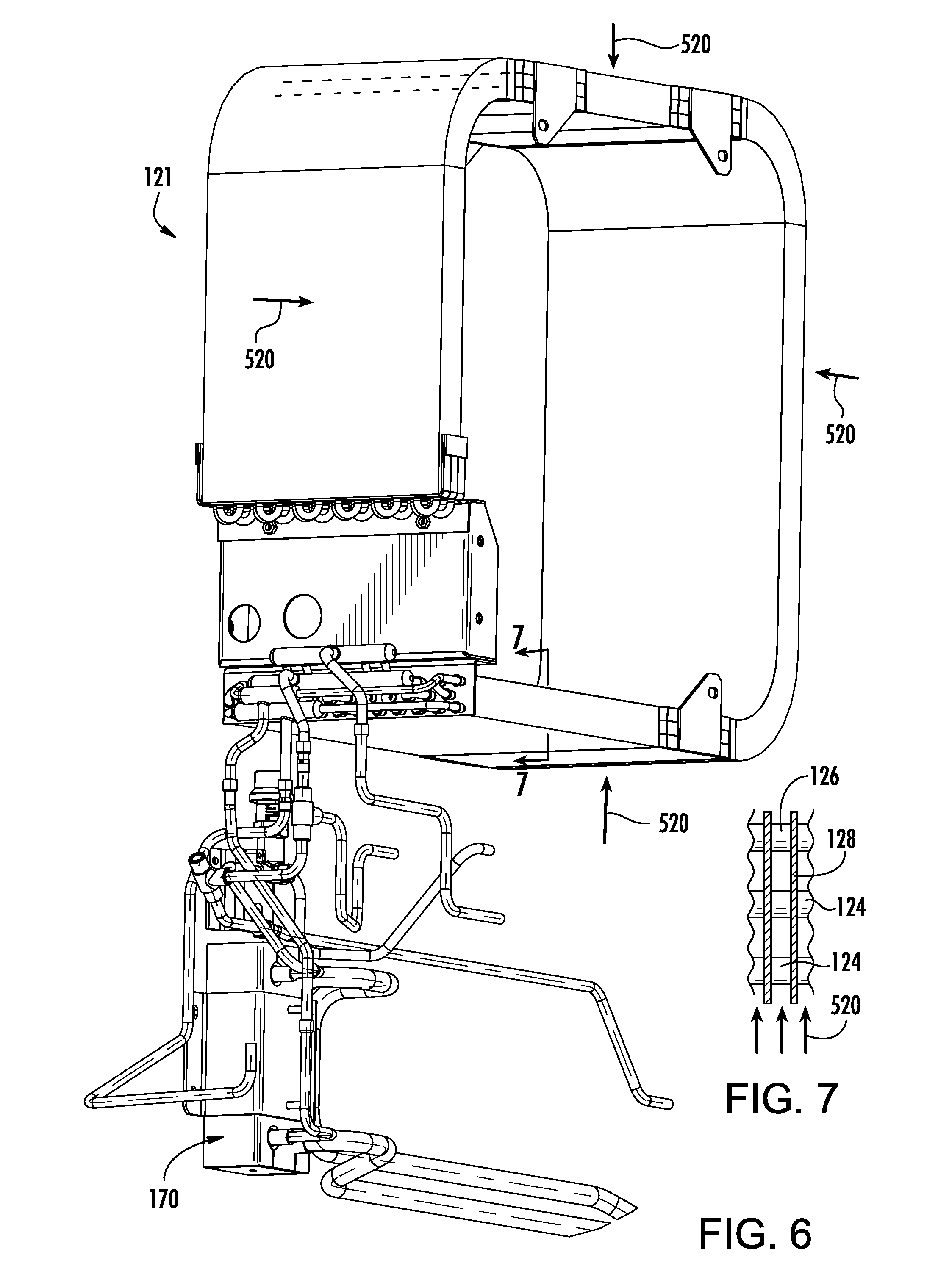
[0032] FIG. 6 is a partial view of a subassembly of an air-cooled condenser/intercooler and water-cooled condenser.
[0033] FIG. 7 is a partial cross-sectional view of the air-cooled condenser/intercooler taken along line 7-7.
[0034] FIG. 8 is a simplified view of a containerized cargo ship.
[0035] FIG. 9 is a simplified partial schematic view of a cooling water supply system of the ship.
[0036] Like reference numbers and designations in the various drawings indicate like elements.
DETAILED DESCRIPTION
[0037] FIG. 1 shows an intermodal container 20 that may be shipped, trucked, trained or the like. The container has a body 22 enclosing an interior 24. The body and interior are formed essentially as right parallelepipeds. The body has a top 22A, a bottom 22B, a first side 22C, a second side 22D, a first end 22E and a second end 22F. The top, bottom, and sides may be an integral rigid metallic structural system. The first end may be closed by an equipment module 26 ("equipment box"). The second end may essentially be formed by a pair of oppositely hinged doors 28A, 28B (FIG. 2).
[0038] The exemplary pair of rear doors 28A, 28B (FIG. 2) are hinged along their outboard edges to the adjacent sides and meet at their inboard edges. To secure the doors in place, each door has a pair of vertically oriented locking bars mounted in bushings for rotation about their central vertical axes. At upper and lower ends, each of the locking bars has a cam which may interact with an associated complementary keeper mounted in the rear header and rear sill respectively. The locking bars may rotate by approximately 90.degree. or up to approximately 180.degree. between a locked condition wherein the cams interlock with the keepers and an unlocked condition where the cams may pass free from the keepers as the doors are rotated between their opened and closed conditions.
[0039] The equipment module contains a vapor compression refrigeration system 30 (FIG. 3). The exemplary system uses a carbon dioxide based refrigerant such as R-744. The illustrated example comprises, sequentially along a main portion of a refrigerant flowpath 34, a compressor 36, a heat rejection heat exchanger 38, an expansion device 40 (e.g., electronic expansion valve, thermal expansion valve, orifice, or the like), and a heat absorption heat exchanger 42. One or more first fans 50 may drive an external airflow 520 across the heat rejection heat exchanger. The heat rejection heat exchanger is thus referred to as an air-cooled condenser (ACC). The term "condenser" is used in the art in a broad sense to comprehend both true condensers and gas coolers. One or more second fans 52A, 52B (FIGS. 3 and 4) may drive an internal airflow 522A, 522B along respective flowpaths 510A, 510B across the heat absorption heat exchanger.
[0040] In various implementations, for powering the container, there may be a power cord (not shown) for connecting to an external power source. For example, the external power source may be from the ship or truck-trailer carrying the container or may be from a facility or yard in which the container is stored. Additionally, the container may be associated with a generator 60 (FIG. 3, e.g., having an internal combustion engine). For intermodal containers, the generator may be a part of an accessory "genset" that may separately mount to a vehicle (trailer or rail car) carrying the container. Other transport refrigeration systems such as dedicated trailers may integrate the generator into an equipment body mounted to the front of the trailer box. The refrigeration system may include a main controller 64 (e.g., having a processor, memory and storage for running a program to perform the required functions) powered by a main battery 66. The battery is typically a rechargeable battery that charges when the container is plugged into external power or a running genset.
[0041] For ease of manufacture or service, the equipment module may be pre-formed as a module mateable to a remainder of the container body (e.g., insertable into an open front end of the body).
[0042] The module 26 comprises a front panel or panel assembly 70 (FIG. 4). In FIGS. 1 and 4, a lower right (in the drawing; left on the container) panel of the assembly 70 is shown cut away. To the left side of the drawing, lower panels are removed to expose various components. The panel assembly 70 may have a plurality of openings of which some may be closed by various means. Two of the openings are along the respective air flowpaths 510A, 510B of the two evaporator fans 52A and 52B. These flowpaths may be isolated from each other or may merely be adjacent halves of a single flowpath (or may be a combination, separating and merging). In this example, the opening spans the fan, so that a portion of the opening is upstream of the fan and a portion of the opening is downstream. The openings are closed by respective access panels 80A, 80B (FIG. 4). The exemplary panel 80A includes a rotary gate valve (e.g., manual or motorized) for venting for fresh air exchange. It may also have a small blower fan 81A to withdraw air from the flowpath 510A (or may rely on leakage across the adjacent evaporator fan). Other valve/gate structures may be provided. The illustrated panel 80B lacks any vent/valve and/or blower but may also have one.
[0043] The exemplary system 30 is an economized system. An exemplary economized system has the compressor as a two-stage compressor having respective first and second stages 36A and 36B. In the exemplary embodiment, the first stage 36A and the second stage 36B are, respectively, a low pressure stage and a high pressure stage. The exemplary stages are commonly powered by a motor 37. For example, the stages may be separate cylinder banks of a reciprocating compressor. FIG. 3 shows the compressor having an overall suction port 90 and an overall discharge port 92. An economizer port is labeled 94. An exemplary economizer involves a flash tank economizer subsystem 100 located between the heat rejection heat exchanger 38 and the expansion device 40. The exemplary system 100 comprises a flash tank 102 having a liquid outlet 104 for feeding the expansion device 40 and a vapor outlet 106 for feeding saturated vapor along an economizer line 108 to the economizer port 94. Typically the mixing of saturated vapor helps cool (lower) the temperature of the refrigerant leaving the first stage. This and the intercooler together serve to lower that temperature to keep the second stage temperature (the discharge temperature) from getting too high. An economizer expansion device 110 may be integrated with the flash tank or upstream of an inlet 112 of the flash tank. The exemplary expansion device 110 is a conventional high pressure expansion valve.
[0044] The exemplary refrigeration system is also an intercooled system having an intercooler heat exchanger 120. The intercooler heat exchanger may, in at least some operational modes, be between the first stage 36A and second stage 36B along the refrigerant flowpath. The exemplary intercooler heat exchanger (intercooler) 120 is a refrigerant-air heat exchanger. The exemplary refrigerant-air heat exchanger is along the external air flowpath 508. In the exemplary embodiment, the intercooler heat exchanger 120 is downstream of the heat rejection heat exchanger 38 along said flowpath 508. As is discussed further below, the heat exchangers 38 and 120 may be integrated in a single air-cooled condenser/intercooler unit 121 (FIG. 6) with separate tube legs 124 associated with the heat exchanger 38 and 126 associated with the heat exchanger 120. The exemplary combined unit is a fin-tube heat exchanger (e.g., round tube plate fin (RTPF)) wherein metallic fins 128 and tube sheets are shared by both sets of tube legs. Other configurations may intermix tubes and the exact balance of tubes associated with the respective legs may be dictated by various performance factors.
[0045] The intercooler is located along an interstage line 130 (FIG. 3) forming an interstage leg 34-1 of the flowpath 34. The interstage line extends from a port 134 on the compressor. In the exemplary intercooled and economized embodiment, the intercooler line 130 merges with the economizer line 108 such that the intercooler refrigerant flow may return to the second stage via the economizer port 94.
[0046] FIG. 3 shows a number of additional features that may be conventional in a baseline economized and intercooled system. These include a valve 140 along the economizer line (e.g., an economizer solenoid valve) which may selectively permit and block the economizer flow. A check valve 142 along the economizer line prevents reverse flow through the port 106. An unloading valve 144 (e.g., an unloader solenoid valve) is positioned along an unloading line 146 extending from the second stage inlet (economized port) condition back to the first stage inlet (suction port 90) condition. In the exemplary embodiment, this is shown extending between a junction of the lines 108 and 130 and a suction line upstream of the suction port 90. Physical arrangements other than those illustrated may achieve the same fluidic conditions.
[0047] Among other conventional features are a filter/dryer 150, a high side charging port 152, a low side charging port 153, a low side pressure relief valve 154, a high side pressure relief valve 156, various pressure sensors 158, various temperature sensors 160, and a flash tank pressure relief valve 162.
[0048] To the exemplary baseline refrigeration system, the system 30 adds a water-cooled heat rejection heat exchanger 170 (aka, water-cooled condenser) upstream of the heat rejection heat exchanger 38 along the refrigerant flowpath. The heat exchanger 170 places a water flowpath 172 in heat exchange relation with the refrigerant flowpath. Although the term "water" is used, as a practical matter, flow in the flowpath 172 will typically not be pure water but may have one or more of various additives for bacterial control, corrosion inhibition, freeze protection, pump lubrication, and the like. This water is identified in the art as "grey water". FIG. 3 shows an inlet fitting 174 and an outlet fitting 176 along the flowpath 172. A water pressure sensor 178 may be long the flowpath 172 somewhere between the fittings. As is discussed below, these may be connected to respective supply 180 and return 182 lines via respective fittings 184, 186 (e.g., self-draining quick-connect fittings) to supply cool water and return warmed water. To prevent misconnection, the fittings 174 and 176 may differ from each other such as being of opposite sex.
[0049] The system 30 may have one or more non-water-cooled modes wherein there is no flow along the flowpath 172. These may include one or more economized modes and one or more non-economized modes.
[0050] The system 30 also has at least one mode wherein there is water flow along the flowpath 172. As is discussed below, this will occur, for example, when the container is on a ship. With containers stacked on in a ship, inlet airflow along the flowpath 508 may be of relatively warm air due to poor circulation. Absent rejection of heat via the heat exchanger 170, the system 30 may be unable to cool the container under those circumstances. Similarly, otherwise extreme outdoor temperatures may overpower the basic capacity of the system. In such situations, flow along the flowpath 170 pre-cools the refrigerant entering the heat exchanger 38. Depending on circumstances, this cooling may be to a temperature below ambient air temperature.
[0051] In general, control may reflect existing control protocols for water-cooled refrigerated containers and economized/intercooled containers generally. As in a conventional water-cooled system, the pressure sensor 178 may be used by the controller to determine when to switch to water-cooled modes. When threshold water pressure is sensed, the controller may shut off power to the condenser fan 50 while continuing to run the compressor, evaporator fan(s), and other components as normal. When water pressure is not sensed, the controller will operate the condenser fans as normal.
[0052] Cooling of refrigerant entering the heat exchanger 38 allows indirect cooling of refrigerant passing along the intercooler flowpath 34-1. For example, instead of rejecting heat to the airflow 520, the heat exchanger 38 may absorb heat from the airflow 520 and allow the intercooler heat exchanger 120 to, in turn, reject heat to the airflow 520. Another mechanism or dynamic is via direct thermal conduction of heat from the intercooler heat exchanger to the heat exchanger 38. For example, as was noted above, the heat exchangers 38 and 120 may be two sections of a single physical unit. For example, the single unit may be a plate fin heat exchanger wherein the two sections are formed by different individual tube legs 124, 126 (FIG. 7) but sharing fins 128. The fins may conduct heat from the tubes of the intercooler heat exchanger section to the tubes of the heat exchanger section 38. In such a situation, the fan 50 may be shut off to prevent the airflow 520. It is thus seen that by positioning the water-cooled condenser 170 upstream of the air-cooled condenser 38, the water-cooled condenser 170 can provide direct cooling of refrigerant along the main flowpath and indirect cooling of refrigerant along the intercooler flowpath to allow intercooled operation in a water-cooled mode. This avoids, for example, the need to provide a second water cooled heat exchanger along the intercooler flowpath 34-1.
[0053] FIG. 8 shows a cargo ship 600 carrying a plurality 602 of containers stacked topside and a plurality 604 of containers within a compartment in the interior of the hull 606 of the ship. Schematically, a cooling water system 618 on the ship comprises a seawater side 620 including one or more inlet ports 622 for drawing in seawater and one or more discharge ports 624 for discharging seawater. One or more pumps 626 may drive a flow of seawater from the inlet(s) to the outlet(s) and through the seawater side of one or more water-water heat exchangers 630. On a grey water side 640, one or more pumps 642 drive flow through the grey water side(s) of a heat exchanger(s) 630. Various supply and return manifold structures 660, 662 may ultimately culminate in the individual supply 180 and return 182 lines for the individual containers. Other details such as various filters, sterilizers, expansion tanks/buffers, and the like are not shown but may be included as are known or yet to be developed in the art.
[0054] The system may be made using otherwise conventional or yet-developed materials and techniques.
[0055] The use of "first", "second", and the like in the description and following claims is for differentiation within the claim only and does not necessarily indicate relative or absolute importance or temporal order. Similarly, the identification in a claim of one element as "first" (or the like) does not preclude such "first" element from identifying an element that is referred to as "second" (or the like) in another claim or in the description.
[0056] One or more embodiments have been described. Nevertheless, it will be understood that various modifications may be made. For example, when applied to an existing basic refrigeration system and/or container construction and associated use methods, details of such existing configuration or its associated use may influence details of particular implementations. Accordingly, other embodiments are within the scope of the following claims.
* * * * *
D00000
D00001
D00002
D00003
D00004
D00005
D00006
D00007
XML
uspto.report is an independent third-party trademark research tool that is not affiliated, endorsed, or sponsored by the United States Patent and Trademark Office (USPTO) or any other governmental organization. The information provided by uspto.report is based on publicly available data at the time of writing and is intended for informational purposes only.
While we strive to provide accurate and up-to-date information, we do not guarantee the accuracy, completeness, reliability, or suitability of the information displayed on this site. The use of this site is at your own risk. Any reliance you place on such information is therefore strictly at your own risk.
All official trademark data, including owner information, should be verified by visiting the official USPTO website at www.uspto.gov. This site is not intended to replace professional legal advice and should not be used as a substitute for consulting with a legal professional who is knowledgeable about trademark law.