Adjustable Capacity Gas Incinerator
Sutherland; John
U.S. patent application number 15/801362 was filed with the patent office on 2019-05-02 for adjustable capacity gas incinerator. The applicant listed for this patent is Questor Technology, Inc.. Invention is credited to John Sutherland.
| Application Number | 20190128517 15/801362 |
| Document ID | / |
| Family ID | 66242808 |
| Filed Date | 2019-05-02 |


| United States Patent Application | 20190128517 |
| Kind Code | A1 |
| Sutherland; John | May 2, 2019 |
Adjustable Capacity Gas Incinerator
Abstract
An adjustable capacity gas incinerator includes a base portion defining a lower chamber through which combustion air can flow from outside the gas incinerator into the lower chamber. A combustion stack extending vertically upward from the base portion and having a wall defining a combustion chamber and a combustion gas exit opening through which products of combustion can exit the combustion chamber. The combustion stack includes a lower stack section and an upper stack section removably joined to the lower stack section and which is removable from the lower stack section to change a combustion capacity of the combustion chamber.
| Inventors: | Sutherland; John; (Calgary, CA) | ||||||||||
| Applicant: |
|
||||||||||
|---|---|---|---|---|---|---|---|---|---|---|---|
| Family ID: | 66242808 | ||||||||||
| Appl. No.: | 15/801362 | ||||||||||
| Filed: | November 2, 2017 |
| Current U.S. Class: | 1/1 |
| Current CPC Class: | F23G 5/24 20130101; F23G 7/085 20130101; F23G 5/50 20130101; F23D 14/60 20130101; F23J 2213/203 20130101; F23G 7/06 20130101 |
| International Class: | F23G 5/50 20060101 F23G005/50; F23G 7/08 20060101 F23G007/08; F23D 14/60 20060101 F23D014/60 |
Claims
1. A method for incinerating gas comprising the steps of: providing a gas incinerator that has a base portion defining a lower chamber through which combustion air can flow from outside the gas incinerator into said lower chamber, a combustion stack extending vertically upward from said base portion and having a wall defining a combustion chamber in communication with said lower chamber at one end and a combustion gas exit opening at its opposite end through which products of combustion can exit said combustion chamber, and said combustion stack having a lower stack section and an upper stack section removably connected to said lower stack section by a bolt and flange coupling; injecting gas from a source of gas at a flow rate into said combustion chamber and combusting said gas in said combustion chamber; and removing said upper stack section from said lower stack section when said flow rate of said gas declines to a rate in which said upper stack section is not required to maintain combustion of said gas without said combustion occurring beyond said combustion gas exit opening.
2. A gas incinerator comprising: a base portion defining a lower chamber through which combustion air can flow from outside the gas incinerator into said lower chamber; a combustion stack extending vertically upward from said base portion and having a wall defining a combustion chamber and a combustion gas exit opening through which products of combustion can exit said combustion chamber; and wherein said combustion stack includes a lower stack section and an upper stack section removably joined to said lower stack section and which is removable from said lower stack section to change a combustion capacity of said combustion chamber.
3. The gas incinerator of claim 2, wherein said lower stack section and said upper stack section are removably joined together by a bolted flange coupling.
4. The gas incinerator of claim 3, wherein said bolted flange coupling includes a first flange member extending around said wall of said lower stack section and a second flange member extending around said wall of said upper stack section.
5. The gas incinerator of claim 3, wherein said first flange member reinforces said wall of said lower stack section and wherein said second flange member reinforces said wall of said upper stack section.
6. The gas incinerator of claim 2, further comprising one or more lifting lugs disposed on said upper stack section.
7. The gas incinerator of claim 6, wherein said one or more lifting lugs are removably connected to said upper stack section.
Description
FIELD OF THE INVENTION
[0001] The present invention relates generally to gas incinerators, and more particularly, relating to a gas incinerator that completely combusts gas without visible flames at the outlet for the combustion gases and that has a variable capacity that is adjustable according to combustion demand.
BACKGROUND OF THE INVENTION
[0002] There are several factors that govern the gas flow rate capacity of a gas incinerator and one of those is the height of the combustion stack. All other design features being identical, a taller combustion stack has higher efficiency than a lower combustion stack. Within the oil and gas industry, there are many areas where gas incineration is required. Two of the most common are initial well flow backs and production facilities. Due to the potential for large fluctuation in gas flow rates between these two activities, it is challenging to adequately serve both important needs. It has been a customary practice for industry to rent large capacity incinerators for the initial flow backs and then remove those after a sufficient wellbore evaluation flow back period to make room for the purchase of many small incinerators for their production facilities. This is an expensive and time-consuming process.
[0003] Oil and gas wells initially flow at high rates and, after the initial flow period, there is a natural decline and reduction in flow rate from the wells prior to the production facility being commissioned. Another contributing factor is that many production facilities will have pipelines being constructed to transport gas away from the production facility, however, those pipelines often cannot accommodate the full gas flows. For these reasons incinerators are required for production facilities but for reduced capacities as compared to the initial well capacities.
[0004] Accordingly, there is a need for a single gas incinerator having a combustion capacity capable of handling an initial, high gas flow rate and, then once the gas flow rate declines, the combustion capacity can be reduced to meet the lower gas flow rate, thereby eliminating the need to install a high capacity incinerator and then replace the high capacity incinerator with smaller capacity incinerator.
SUMMARY OF THE INVENTION
[0005] The present specification describes a gas incinerator having a combustion capacity that can handle an initial, high flow gas rate and, then once the gas flow rate declines, the combustion capacity is adjustable to meet combustion demand of the declined gas flow rate. Combustion capacity is adjustable by providing a combustion stack having a stack height that can be decreased to meet combustion demands.
[0006] The present gas incinerator would be set in the precise location where the smaller lower capacity incinerator would normally be set up. Once the wellbore evaluation period was completed the top portion of the combustion stack would be removed and a smaller, but appropriate, capacity stack would remain to serve the requirements of the production facility. In other words, what was traditionally a temporary incinerator would become the permanent incinerator, by removing the top portion.
[0007] This is an operational breakthrough in that industry significantly reduces equipment handling and their overall lease size. Further, purchasing the bottom portion of the incinerator and renting the top portion is much more economical than current practice where a full incinerator is rented and then replaced by purchasing a completely different designed production incinerator. The removed tops would then be re-used on incinerator bottoms on other projects and the operation simply repeats.
[0008] According, in general, in one aspect, a method for incinerating gas is provided. The method comprising the steps of: [0009] a. providing a gas incinerator that has a base portion defining a lower chamber through which combustion air can flow from outside the gas incinerator into the lower chamber, a combustion stack extending vertically upward from the base portion and having a wall defining a combustion chamber in communication with the lower chamber at one end and a combustion gas exit opening at its opposite end through which products of combustion can exit the combustion chamber, and the combustion stack having a lower stack section and an upper stack section removably connected to the lower stack section by a bolt and flange coupling; [0010] b. injecting gas from a source of gas at a flow rate into the combustion chamber and combusting the gas in the combustion chamber; and [0011] c. removing the upper stack section from the lower stack section when the flow rate of the gas declines to a rate in which the upper stack section is not required to maintain combustion of the gas without the combustion occurring beyond the combustion gas exit opening.
[0012] In general, in another aspect, a gas incinerator with a variable combustion capacity is provided. The gas incinerator includes a base portion defining a lower chamber through which combustion air can flow from outside the gas incinerator into the lower chamber. A combustion stack extending vertically upward from the base portion and having a wall defining a combustion chamber and a combustion gas exit opening through which products of combustion can exit the combustion chamber. The combustion stack includes a lower stack section and an upper stack section removably joined to the lower stack section and which is removable from the lower stack section to change a combustion capacity of the combustion chamber.
[0013] There has thus been outlined, rather broadly some features of the invention so that the detailed description thereof that follows may be better understood and so that the present contribution to the art may be better appreciated.
[0014] Numerous objects, features and advantages of the present invention will be readily apparent to those of ordinary skill in the art upon a reading of the following detailed description of presently preferred, but nonetheless illustrative, embodiments of the present invention when taken in conjunction with the accompanying drawings. The invention is capable of other embodiments and of being practiced and carried out in numerous ways. Also, it is to be understood that the phraseology and terminology employed herein are for description and should not be regarded as limiting.
[0015] As such, those skilled in the art will appreciate that the conception, upon which this disclosure is based, may readily be utilized as a basis for the designing of other structures, methods and systems for carrying out the several purposes of the present invention. It is important, therefore, that the claims be regarded as including such equivalent constructions insofar as they do not depart from the spirit and scope of the present invention.
[0016] For a better understanding of the invention, its operating advantages and the specific objects attained by its uses, reference should be had to the accompanying drawings and descriptive matter in which there are illustrated embodiments of the invention.
BRIEF DESCRIPTION OF THE DRAWINGS
[0017] The following drawings illustrate by way of example and are included to provide further understanding of the invention for illustrative discussion of the embodiments of the invention. No attempt is made to show structural details of the embodiments in more detail than is necessary for a fundamental understanding of the invention, the description taken with the drawings making apparent to those skilled in the art how the several forms of the invention may be embodied in practice. Identical reference numerals do not necessarily indicate an identical structure. Rather, the same reference numeral may be used to indicate a similar feature of a feature with similar functionality In the drawings:
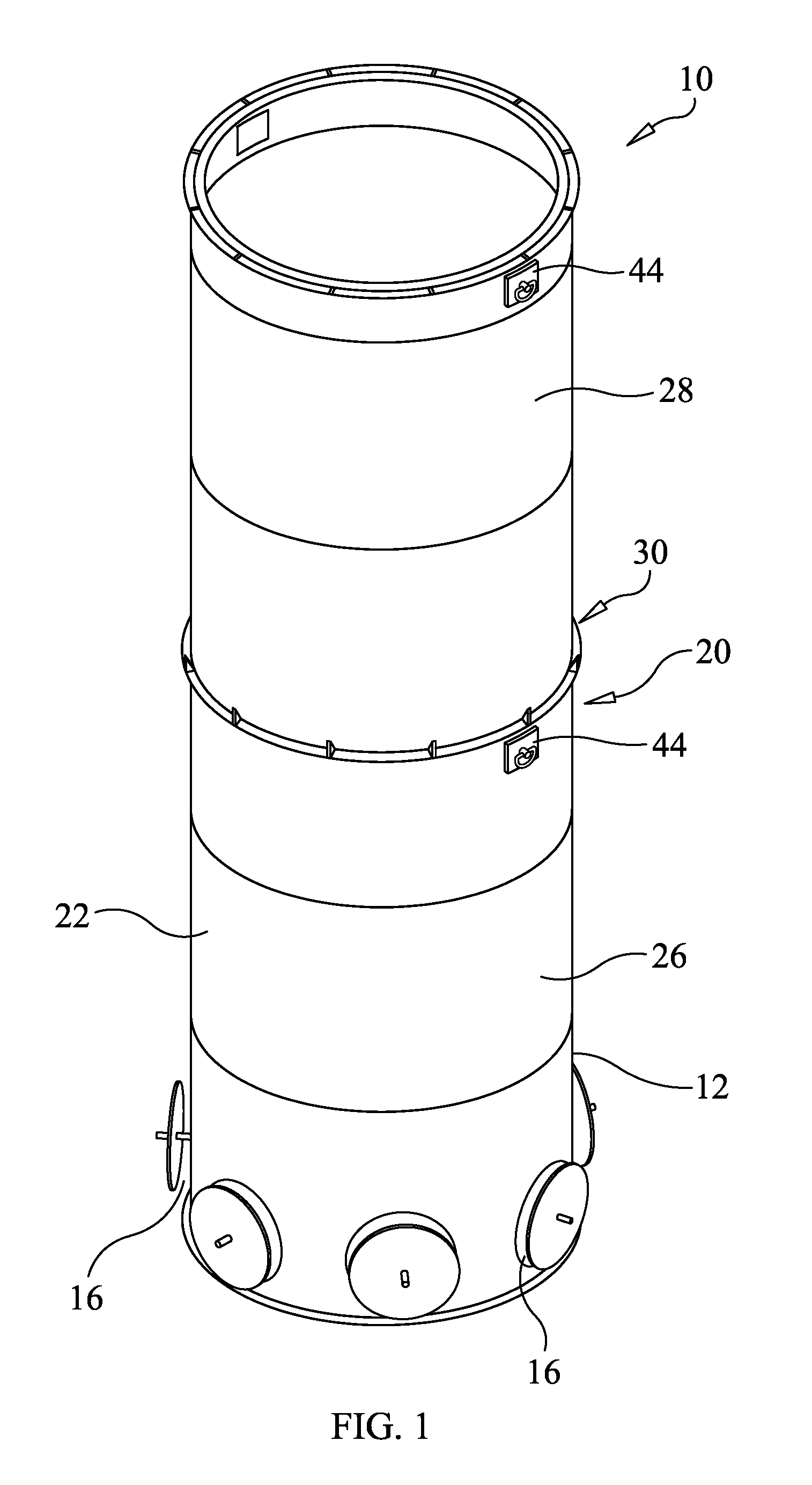
[0018] FIG. 1 is a diagrammatic perspective view of an adjustable capacity gas incinerator constructed in accordance with the principles of an embodiment of the present invention;
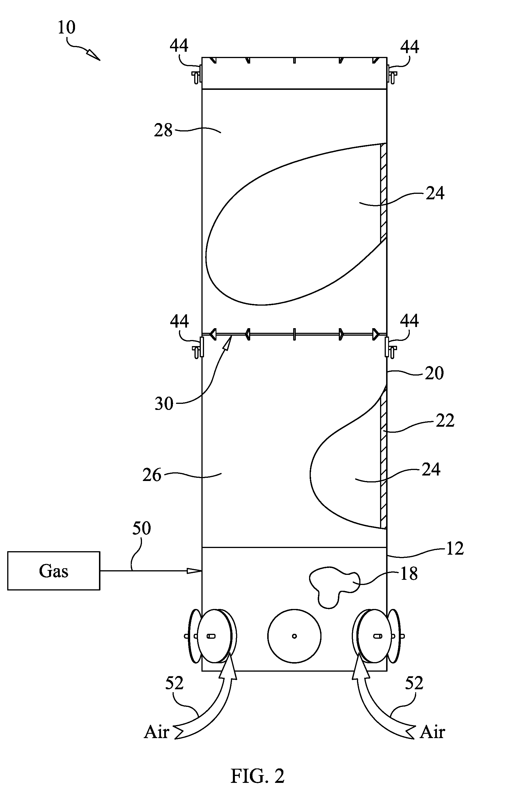
[0019] FIG. 2 is a diagrammatic front view of the gas incinerator of FIG. 1 in partial cross-section;
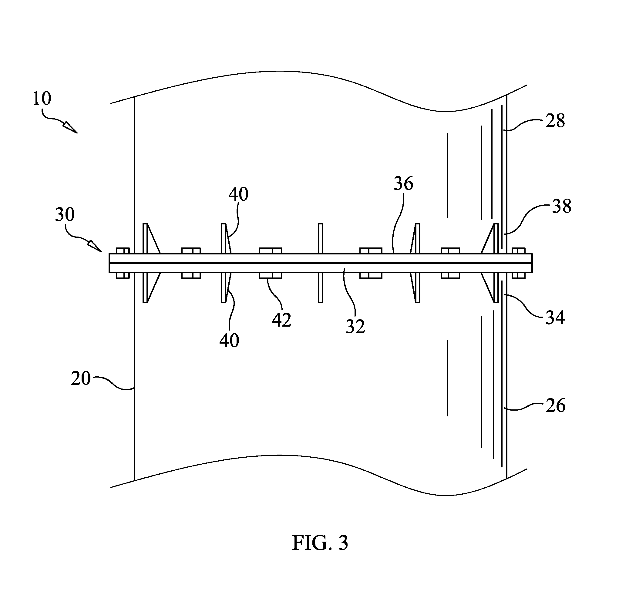
[0020] FIG. 3 is an enlarged, diagrammatic view of a bolted flange connection between two combustion stack sections;
[0021] FIG. 4 is a diagrammatic, partial perspective view of a lower combustion stack section shown with an upper combustion stack section removed therefrom; and
[0022] FIG. 5 is a diagrammatic, partial cross-section view showing a lifting lug removably attached to a combustion stack section.
DETAILED DESCRIPTION OF THE INVENTION
[0023] With initial reference to FIGS. 1 through 2, there is representatively illustrated a new gas incinerator 10 in accordance with an embodiment of the present invention. The incinerator 10 includes a base portion 12 defined by a cylindrical side wall 14 that has a plurality of air openings 16 spaced therearound. The base portion 12 defines a lower chamber 18, which receives ambient air located outside the incinerator through openings 16. A combustion stack 20 extends vertically upward from the base portion 12 and has a wall 22 that defines a combustion chamber 24 that is in direct communication with the lower chamber 18. The incinerator 10 includes a combustion system for combusting gas injected into the combustion chamber, such as the combustion system described by U.S. Pat. No. 6,168,422, the entirety of which is incorporated herein by reference.
[0024] The combustion stack 20 is divided along its height into a lower stack section 26 and an upper stack section 28. The upper stack section 28 is joined to the lower stack section 26 to create a continuous combustion stack 20 with combustion chamber 24 extending the height of the combustion stack. The upper stack section 28 and the lower stack section are removably coupled together by a bolted flange connection 30. The upper stack section 28 can be removed from the lower stack section 26 to change the height of the combustion stack 20 and, thus, the capacity of the combustion chamber 24. The lengths or heights of the lower stack section 26 and the upper stack section 28 may be varied to meet combustion requirements of an installation. For example, the upper and lower stack sections 28 and 26 may have the same or different heights (lengths).
[0025] Detail of the bolted flange connection 30 is shown in FIG. 3. The bolted flange connection 30 includes a first flange member 32 disposed around a top end 34 of the lower stack portion 26 and a second flange member 36 disposed around a bottom end 38 of the upper stack portion 28. The flange members 32 and 36 are supported by a plurality of gussets 40. The flange members 32 and 36 are connected by a plurality of bolts 42 that extend through cooperating holes formed through the flange members. With reference to FIG. 4, there is shown a partial view of the combustion stack 20 with the upper stack section 28 removed from the lower stack section 26.
[0026] The mating flanges 32 and 36 on the upper and lower stack sections 28 and 26 serve an additional purpose. The cylindrical stack is designed with a wall thickness that requires mechanical strengthening in to be transported and set up. Without added mechanical strength the incinerator's steel walls might experience a deformation or buckling during these activities. The flanges add strength to mitigate this and the mechanical qualities of the flange have been modeled appropriately to provide sufficient mechanical integrity.
[0027] The incinerator 10 also includes lifting lugs 44 for lifting and positioning the incinerator and stack sections and, particularly, for lifting and positioning the upper stack section 28 on the lower stack section 26. Turning to FIG. 5, each lifting lug 44 is removably attached to the sidewall 22 of the stack section 26, 28 by a bolt 46 that is threaded through front and back plates 48 and 50 welded to opposite sides of the sidewall 22.
[0028] In operation, the incinerator 10 is initially configured with the combustion stack 20 having the upper stack section 28 secured to the lower stack portion 26 to provide a combustion chamber 24 having a first combustion capacity according an initial flow rate of a source gas 50 that is to be burned. The height of the combustion stack 20 is such that combustion of the source gas 50 mixed with air 52 is entirely contained within the combustion chamber so that no flames exit the combustion gas exit located at the top end of the stack. Once the initial flow rate of the source gas 50 declines to a rate that combustion can be supported entirely within the lower stack section 26 alone, the upper stack section 28 is disconnected from the lower stack section and removed, thereby changing the combustion capacity of the combustion chamber 24.
[0029] An embodiment of the present invention has been described. Nevertheless, it will be understood that various modifications may be made without departing from the spirit and scope of the invention. Accordingly, other embodiments are within the scope of the following claims. For example, while the description made herein describes the combustion stack comprised of two sections, the lower section 26 and the upper section 28, the combustion stack could be comprised of more than two sections to allow for finer combustion capacity adjustments.
* * * * *
D00000
D00001
D00002
D00003
D00004
XML
uspto.report is an independent third-party trademark research tool that is not affiliated, endorsed, or sponsored by the United States Patent and Trademark Office (USPTO) or any other governmental organization. The information provided by uspto.report is based on publicly available data at the time of writing and is intended for informational purposes only.
While we strive to provide accurate and up-to-date information, we do not guarantee the accuracy, completeness, reliability, or suitability of the information displayed on this site. The use of this site is at your own risk. Any reliance you place on such information is therefore strictly at your own risk.
All official trademark data, including owner information, should be verified by visiting the official USPTO website at www.uspto.gov. This site is not intended to replace professional legal advice and should not be used as a substitute for consulting with a legal professional who is knowledgeable about trademark law.