Low Peak Insertion Tube End Form
Fremont; Bradley C.
U.S. patent application number 15/799392 was filed with the patent office on 2019-05-02 for low peak insertion tube end form. The applicant listed for this patent is Oetiker NY, Inc.. Invention is credited to Bradley C. Fremont.
| Application Number | 20190128460 15/799392 |
| Document ID | / |
| Family ID | 62817095 |
| Filed Date | 2019-05-02 |


| United States Patent Application | 20190128460 |
| Kind Code | A1 |
| Fremont; Bradley C. | May 2, 2019 |
LOW PEAK INSERTION TUBE END FORM
Abstract
A tube end form, including a first section including a first radially outward facing surface, a second section including a second radially outward facing surface, and a shoulder axially arranged between the first and second sections, the shoulder including a first frusto-conical surface arranged at a first angle relative to the first radially outward facing surface, and a second frusto-conical surface arranged at a second angle relative to the first radially outward facing surface.
| Inventors: | Fremont; Bradley C.; (Tonawanda, NY) | ||||||||||
| Applicant: |
|
||||||||||
|---|---|---|---|---|---|---|---|---|---|---|---|
| Family ID: | 62817095 | ||||||||||
| Appl. No.: | 15/799392 | ||||||||||
| Filed: | October 31, 2017 |
| Current U.S. Class: | 1/1 |
| Current CPC Class: | F16L 47/16 20130101; F16L 47/12 20130101; F16L 37/0885 20190801; F16L 47/08 20130101; F16L 37/04 20130101 |
| International Class: | F16L 47/12 20060101 F16L047/12; F16L 47/08 20060101 F16L047/08; F16L 47/16 20060101 F16L047/16 |
Claims
1. A tube end form, comprising: a first section including a first radially outward facing surface; a second section including a second radially outward facing surface; and, a shoulder axially arranged between the first and second sections, the shoulder including: a first frusto-conical surface arranged at a first angle relative to the first radially outward facing surface; and, a second frusto-conical surface arranged at a second angle relative to the first radially outward facing surface.
2. The tube end form as recited in claim 1, wherein the first angle is not equal to the second angle.
3. The tube end form as recited in claim 2, wherein the first angle is greater than the second angle.
4. The tube end form as recited in claim 3, wherein: the first frusto-conical surface comprises a first adjacent side length; the second frusto-conical surface comprises a second adjacent side length; and, the first adjacent side length is not equal to the second adjacent side length.
5. The tube end form as recited in claim 4, wherein the first adjacent side length is less than the second adjacent side length.
6. The tube end form as recited in claim 1, further comprising a through-bore extending through the first section, the shoulder, and the second section.
7. The tube end form as recited in claim 1, wherein the tube end form is operatively arranged to be inserted into a fluid connector, the fluid connector including: a snap ring; and, a radially inward facing surface.
8. The tube end form as recited in claim 7, wherein: in a first insertion state, the first frusto-conical surface engages the snap ring; and, in a second insertion state, the second frusto-conical surface engages the snap ring.
9. The tube end form as recited in claim 8, wherein when the tube end form is fully inserted within the fluid connector: the first frusto-conical surface is arranged proximate the radially inward facing surface; the second frusto-conical surface is arranged proximate the snap ring; and, the tube end form is prevented from further axial movement by the snap ring and the radially inward facing surface.
10. The tube end form as recited in claim 9, wherein the radially inward facing surface is frusto-conical.
11. The tube end form as recited in claim 1, wherein: the first radially outward facing surface has a first diameter; the second radially outward facing surface has a second diameter; and, the first diameter is not equal to the second diameter.
12. The tube end form as recited in claim 1, wherein: the first radially outward facing surface has a first diameter; the second radially outward facing surface has a second diameter; and, the first diameter is equal to the second diameter.
13. A tube end form, comprising: a first section including a first radially outward facing surface; a second section including a second radially outward facing surface; and, a shoulder axially arranged between the first and second sections, the shoulder including an arcuate surface extending from the first radially outward facing surface.
14. The tube end form as recited in claim 13, wherein the shoulder further comprises a third radially outward facing surface connected to the arcuate surface, the third radially outward facing surface arranged at an angle relative to the first radially outward facing surface.
15. The tube end form as recited in claim 14, wherein the angle is equal to zero.
16. The tube end form as recited in claim 13, further comprising a through-bore extending through the first section, the shoulder, and the second section.
17. The tube end form as recited in claim 14, wherein the tube end form is operatively arranged to be inserted into a fluid connector, the fluid connector including: a snap ring; and, a radially inward facing surface.
18. The tube end form as recited in claim 17, wherein: in a first insertion state, the arcuate surface engages the snap ring; and, in a second insertion state, the third radially outward facing surface engages the snap ring.
19. The tube end form as recited in claim 18, wherein when the tube end form is fully inserted within the fluid connector: the arcuate section is arranged proximate the radially inward facing surface, the radially inward facing surface being frusto-conical; the third radially outward facing surface is arranged proximate the snap ring; and, the tube end form is prevented from further axial movement by the snap ring and the radially inward facing surface.
20. A fluid connection coupling, comprising: a fluid connector, including: a snap ring; and, a radially inward facing surface; and, a tube end form, including: a first section including a first radially outward facing surface; a second section including a second radially outward facing surface; and, a shoulder axially arranged between the first and second sections, the shoulder including: a first frusto-conical surface arranged at a first angle relative to the first radially outward facing surface; and, a second frusto-conical surface arranged at a second angle relative to the first radially outward facing surface, the second angle being less than the first angle; wherein: in a first insertion state, the first frusto-conical surface engages the snap ring; and, in a second insertion state, the second frusto-conical surface engages the snap ring.
Description
FIELD
[0001] The present disclosure relates to a tube end form for a fluid connector, and, more particularly, to a tube end form for a fluid connector including sections having different frusto-conical or curved surfaces arranged on the tube end form to change the force required to insert the tube end form into the fluid connector.
BACKGROUND
[0002] Fluid connectors are integral components for many applications, and especially for automotive applications. Since an automotive system is made up of various components such as a radiator, transmission, and engine, fluid must be able to travel not only within each component but also between components. An example of fluid traveling between components is the transmission fluid traveling from the transmission to the transmission oil cooler in order to lower the temperature of the transmission fluid. Fluid predominantly moves between components via flexible or rigid hoses which connect to each component by fluid connectors.
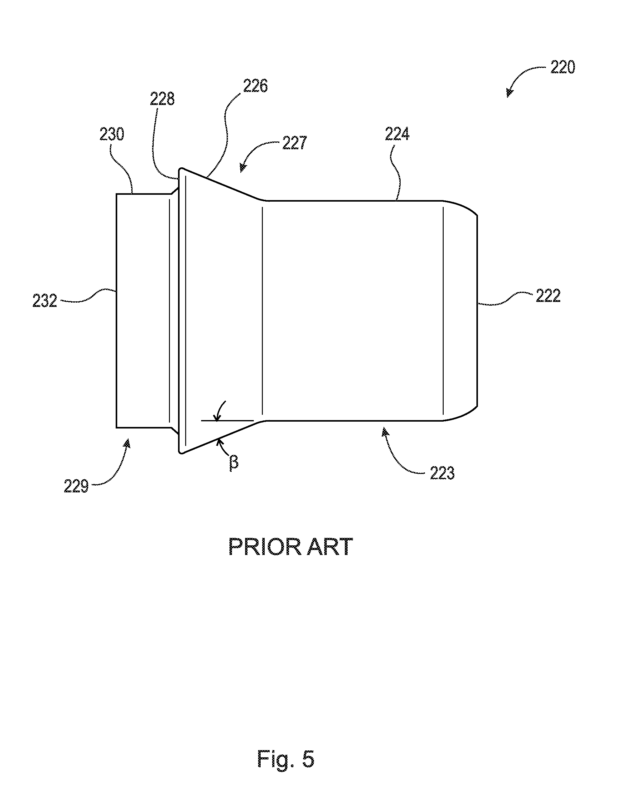
[0003] Traditional tube end forms comprise a straight ramp, which extends radially outward and axially on the outer surface of the tube end form, to displace a wire clip within the fluid connector to secure the tube end form within the fluid connector. FIG. 5 is a side elevational view of prior art tube end form 220. Tube end form 220 comprises end 222, section 223, shoulder 227, section 229, and end 232. Section 223 is arranged between end 222 and shoulder 227 and comprises radially outward facing surface 224. Radially outward facing surface 224 includes a substantially constant diameter. Shoulder 227 is arranged between section 223 and section 229 and comprises radially outward facing surface 226. Radially outward facing surface 226 is a linear conical shape and increases in diameter in axial direction AD1. Section 229 is arranged between shoulder 227 and end 232 and comprises radially outward facing surface 230. Radially outward facing surface 230 includes a substantially constant diameter. Shoulder 227 is connected to radially outward facing surface 230 via shoulder surface 28. Tube end form 220 is arranged to be inserted, specifically with end 222 first, into a fluid connector. Since prior art tube end forms utilize a straight ramp (i.e., constant linear ramp), the insertion effort increases linearly until the clip snaps over the shoulder of the tube end form. In this case, the length and height of the ramp determine the maximum insertion force felt.
[0004] Thus, there has been a long-felt need for a tube end form having a variable ramp to reduce the peak force of insertion.
SUMMARY
[0005] According to aspects illustrated herein, there is provided a tube end form, comprising a first section including a first radially outward facing surface, a second section including a second radially outward facing surface, and a shoulder axially arranged between the first and second sections, the shoulder including a first frusto-conical surface arranged at a first angle relative to the first radially outward facing surface, and a second frusto-conical surface arranged at a second angle relative to the first radially outward facing surface.
[0006] According to aspect illustrated herein, there is provided a tube end form, comprising a first section including a first radially outward facing surface, a second section including a second radially outward facing surface, and a shoulder axially arranged between the first and second sections, the shoulder including an arcuate surface extending from the first radially outward facing surface.
[0007] According to aspect illustrated herein, there is provided a fluid connection coupling, comprising a fluid connector, including a snap ring, and a radially inward facing surface, and a tube end form, including a first section including a first radially outward facing surface, a second section including a second radially outward facing surface, and a shoulder axially arranged between the first and second sections, the shoulder including a first frusto-conical surface arranged at a first angle relative to the first radially outward facing surface, and a second frusto-conical surface arranged at a second angle relative to the first radially outward facing surface, the second angle being less than the first angle, wherein in a first insertion state, the first frusto-conical surface engages the snap ring, and in a second insertion state, the second frusto-conical surface engages the snap ring.
[0008] In order to further encourage assemblers to fully insert the tube end form within the fluid connector, the present invention utilizes a ramp geometry which comprises a steep initial frusto-conical surface, followed by a second frusto-conical surface which has a shallower angle. This ramp geometry reduces the peak insertion force of the tube end form, with a trade-off of an increased initial effort when compared to traditional straight ramp tube end forms.
[0009] Another embodiment of the ramp geometry includes utilizing a curved ramp, comprising an steep initial curve which transitions to a horizontal surface at the termination of the curve. In some cases, the insertion effort can be lowered as the insertion event continues, encouraging the user to "follow through" and fully seat the tube end form in the fluid connector.
[0010] These and other objects, features, and advantages of the present disclosure will become readily apparent upon a review of the following detailed description of the disclosure, in view of the drawings and appended claims.
BRIEF DESCRIPTION OF THE DRAWINGS
[0011] Various embodiments are disclosed, by way of example only, with reference to the accompanying schematic drawings in which corresponding reference symbols indicate corresponding parts, in which:
[0012] FIG. 1 is a perspective view of a tube end form;
[0013] FIG. 2A is a front perspective view of a fluid connector;
[0014] FIG. 2B is a rear perspective view of the fluid connector shown in FIG. 2A;
[0015] FIG. 3A is a side elevational view of the tube end form shown in FIG. 1;
[0016] FIG. 3B is a side elevational view of a tube end form;
[0017] FIG. 3C is a side elevational view of a tube end form;
[0018] FIG. 3D is a side elevational view of a tube end form;
[0019] FIG. 4A is a cross-sectional view of the fluid connector shown in FIG. 2A taken generally along line 4-4 with a tube end form being inserted into the fluid connector;
[0020] FIG. 4B is a cross-sectional view of the fluid connector shown in FIG. 4A with the tube end form being inserted into the fluid connector;
[0021] FIG. 4C is a cross-sectional view of the fluid connector shown in FIG. 4A with the tube end form being inserted into the fluid connector;
[0022] FIG. 4D is a cross-sectional view of the fluid connector shown in FIG. 4A with the tube end form fully inserted in the fluid connector, and,
[0023] FIG. 5 is a side elevational view of a prior art tube end form.
DETAILED DESCRIPTION
[0024] At the outset, it should be appreciated that like drawing numbers on different drawing views identify identical, or functionally similar, structural elements. It is to be understood that the claims are not limited to the disclosed aspects.
[0025] Furthermore, it is understood that this disclosure is not limited to the particular methodology, materials and modifications described and as such may, of course, vary. It is also understood that the terminology used herein is for the purpose of describing particular aspects only, and is not intended to limit the scope of the claims.
[0026] Unless defined otherwise, all technical and scientific terms used herein have the same meaning as commonly understood to one of ordinary skill in the art to which this disclosure pertains. It should be understood that any methods, devices or materials similar or equivalent to those described herein can be used in the practice or testing of the example embodiments. The assembly of the present disclosure could be driven by hydraulics, electronics, and/or pneumatics.
[0027] It should be appreciated that the term "substantially" is synonymous with terms such as "nearly," "very nearly," "about," "approximately," "around," "bordering on," "close to," "essentially," "in the neighborhood of," "in the vicinity of," etc., and such terms may be used interchangeably as appearing in the specification and claims. It should be appreciated that the term "proximate" is synonymous with terms such as "nearby," "close," "adjacent," "neighboring," "immediate," "adjoining," etc., and such terms may be used interchangeably as appearing in the specification and claims. The term "approximately" is intended to mean values within ten percent of the specified value.
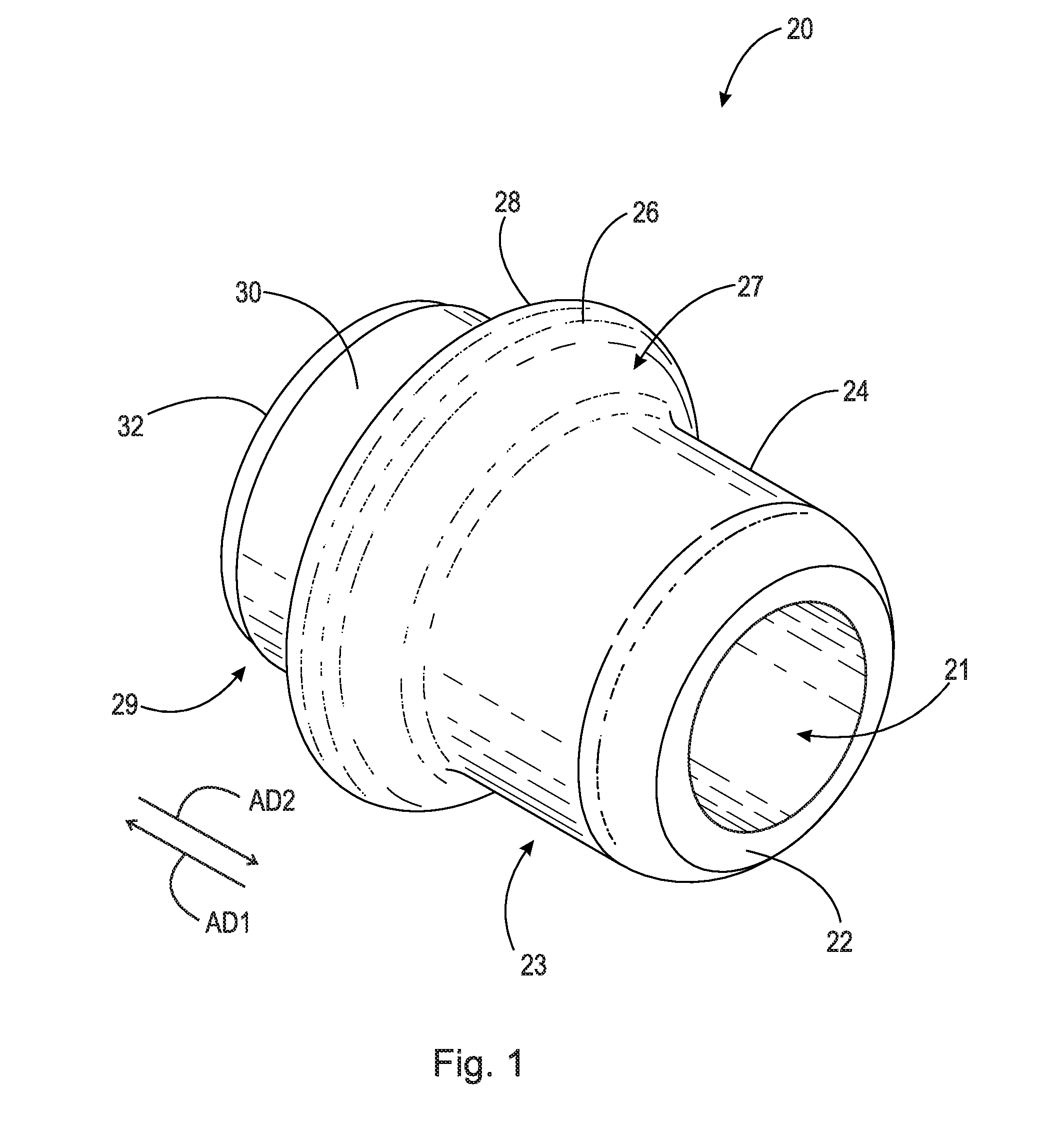
[0028] Adverting now to the figures, FIG. 1 is a perspective view of tube end form 20. Tube end form 20 is generally cylindrical and comprises end 22, section 23, shoulder 27, section 29, end 32, and through-bore 21. Through-bore 21 extends through tube end form 20 from end 22 to end 32. Section 23 is arranged between end 22 and shoulder 27 and comprises radially outward facing surface 24. Radially outward facing surface 24 includes a substantially constant diameter. In an example embodiment, radially outward facing surface 24 includes a variable diameter. Shoulder 27 is arranged between section 23 and section 29 and comprises radially outward facing surface 26. Radially outward facing surface 26 is generally a non-linear conical shape and increases in diameter in axial direction AD1, as will be discussed in greater detail with respect to FIGS. 3A-D. Section 29 is arranged between shoulder 27 and end 32 and comprises radially outward facing surface 30. Radially outward facing surface 30 includes a substantially constant diameter. In an example embodiment, radially outward facing surface 30 includes a variable diameter. Shoulder 27 is connected to radially outward facing surface 30 via shoulder surface 28. In an example embodiment, the diameter of radially outward facing surface 24 is equal to the diameter of radially outward facing surface 30. In an example embodiment, the diameter of radially outward facing surface 24 is not equal to the diameter of radially outward facing surface 30. Tube end form 20 is arranged to be inserted, specifically with end 22 first, into a fluid connector (see FIGS. 4A-D). It should be appreciated that tube end forms 40, 60, and 80 are substantially similar to tube end form 20.
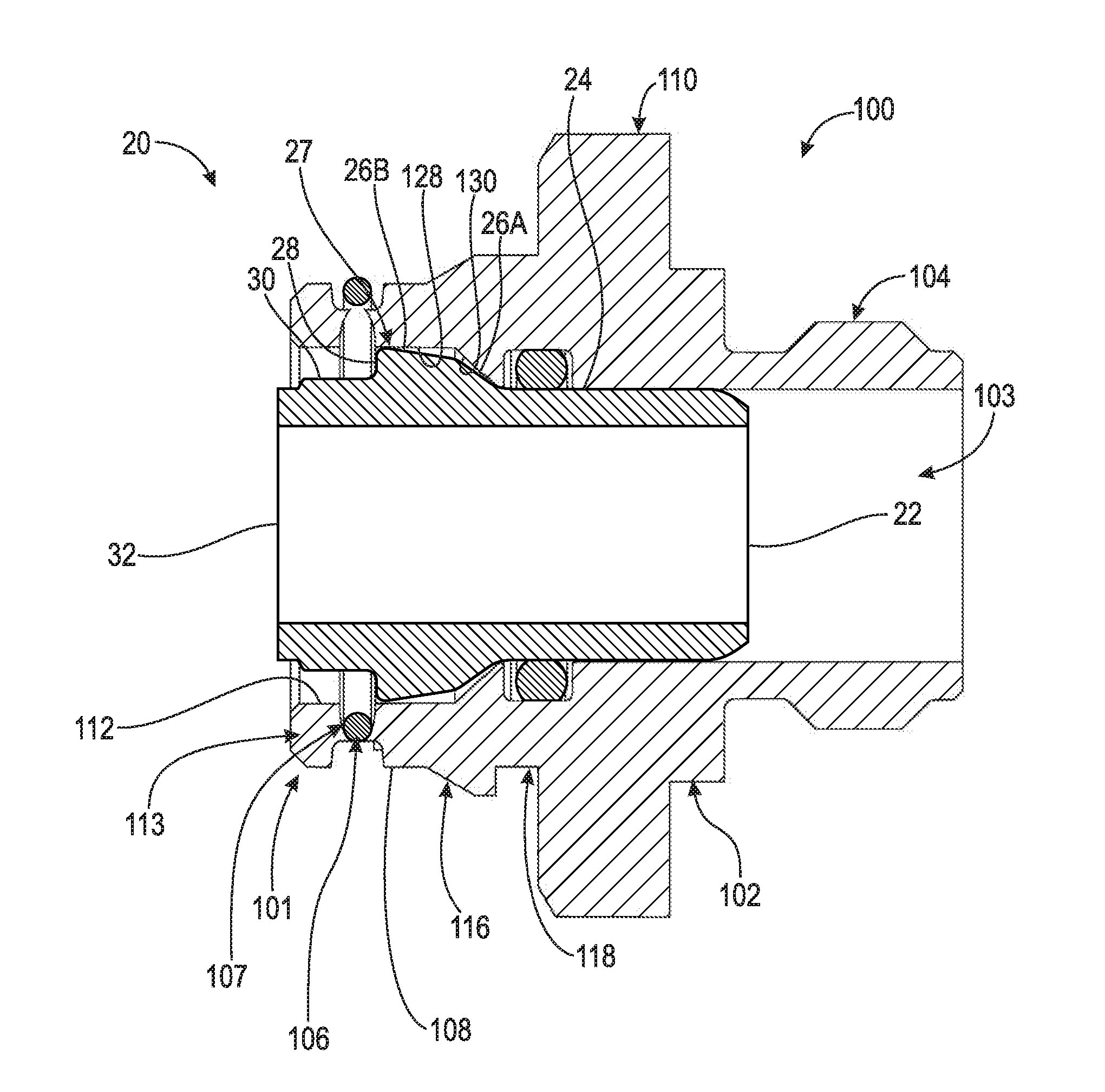
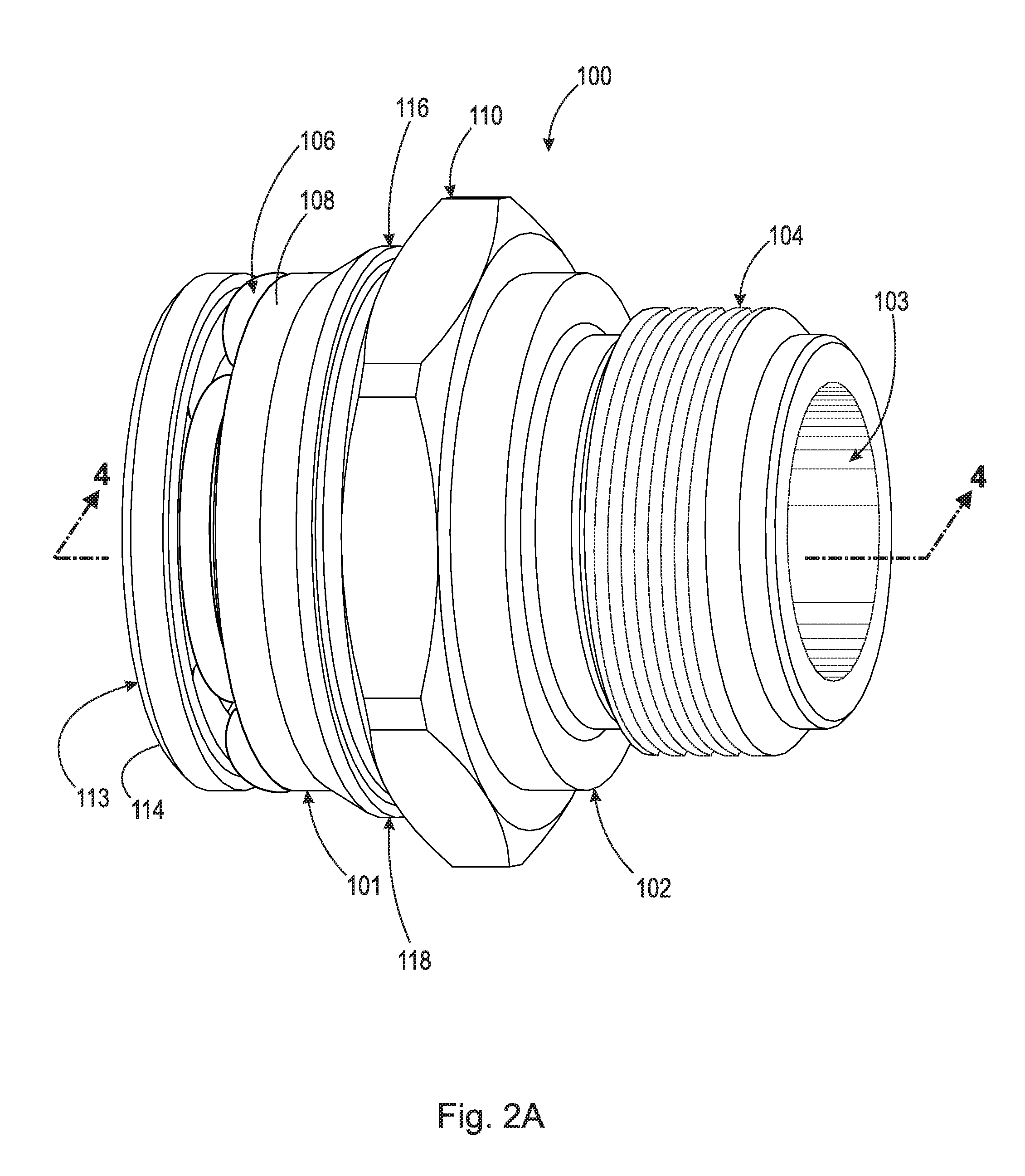
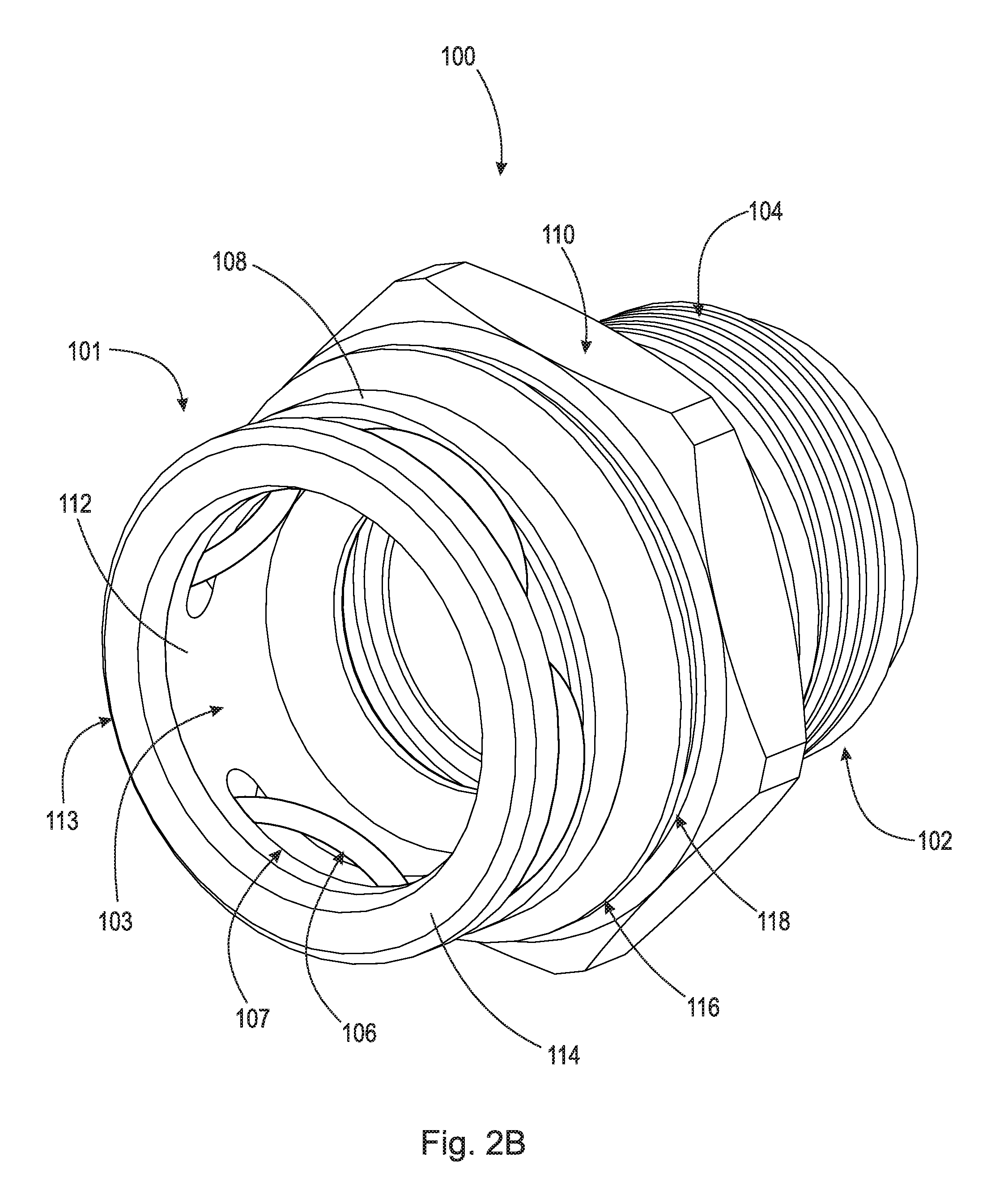
[0029] FIG. 2A and FIG. 2B are a front perspective view and a rear perspective view of fluid connector 100, respectively. Fluid connector 100 comprises section 101 and section 102. Section 101 includes snap ring 106, outer surface 108, inner surface 112, shoulder 113, and shoulder surface 114, shoulder 116, and channel 118. Snap ring 106 is arranged within apertures 107 of fluid connector 100 and secures tubular connector 20 (shown in FIG. 4A) within through-bore 103 of fluid connector 100. Section 102 of fluid connector 100 comprises threads 104 which allow fluid connector 100 to secure to an apparatus such as a transmission, radiator, oil cooler, etc. Fluid connector 100 also includes head 110 which allows a user to use a tool such as a wrench to screw fluid connector 100 into a corresponding apparatus (not shown). Through-bore 103 is arranged in the center of fluid connector 100 and passes through the whole body of fluid connector 100. Fluid connector 100 further comprises radially inward facing surface 128 and radially inward facing surface 130 (shown in FIGS. 4A-D). Radially inward facing surface is preferably conical, and increases/decreases in diameter in a first axial direction.
[0030] FIG. 3A is a side elevational view of tube end form 20. Tube end form 20 is generally cylindrical and comprises end 22, section 23, shoulder 27, section 29, and end 32. Section 23 is arranged between end 22 and shoulder 27 and comprises radially outward facing surface 24. Radially outward facing surface 24 includes a substantially constant diameter. In an example embodiment, radially outward facing surface 24 includes a variable diameter. Shoulder 27 is arranged between section 23 and section 29 and comprises radially outward facing surface 26. Section 29 is arranged between shoulder 27 and end 32 and comprises radially outward facing surface 30. Radially outward facing surface 30 includes a substantially constant diameter. In an example embodiment, radially outward facing surface 30 includes a variable diameter. Shoulder 27 is connected to radially outward facing surface 30 via shoulder surface 28. In an example embodiment, the diameter of radially outward facing surface 24 is equal to the diameter of radially outward facing surface 30. In an example embodiment, the diameter of radially outward facing surface 24 is not equal to the diameter of radially outward facing surface 30.
[0031] Radially outward facing surface 26 is generally a non-linear conical shape and increases in diameter in axial direction AD1. Radially outward facing surface 26 includes conical surface 26A and conical surface 26B. Conical surface 26A is arranged at angle .alpha.1 relative to horizontal axis AX, and has an adjacent side dimension of length L1. Conical surface 26B is arranged at angle .alpha.2 relative to horizontal axis AX, and has an adjacent side dimension of length L2. In the embodiment shown, angle .alpha.1 is not equal to .alpha.2 and length L1 is not equal to L2. In an example embodiment, .alpha.1 is 35.degree. and .alpha.2 is 10.degree.. In an example embodiment, radially outward facing surface 26 may comprise three or more conical surfaces.
[0032] The profile of radially outward facing surface 26 manipulates the insertion force by reducing the peak force with a slight increase in initial effort. Specifically, initial insertion force is increased with a steeper slope, and peak effort is reduced with a shallower angle. In some cases, the insertion effort can be lowered as the insertion event continues, encouraging the user to continue inserting the tube end form until the tube end form is fully seated in the fluid connector. This same effect is achieved with tube end forms 40, 60, and 80, which are described below.
[0033] FIG. 3B is a side elevational view of a tube end form 40. Tube end form 40 is generally cylindrical and comprises end 42, section 43, shoulder 47, section 49, and end 52. Section 43 is arranged between end 42 and shoulder 47 and comprises radially outward facing surface 44. Radially outward facing surface 44 includes a substantially constant diameter. In an example embodiment, radially outward facing surface 44 includes a variable diameter. Shoulder 47 is arranged between section 43 and section 49 and comprises radially outward facing surface 46. Section 49 is arranged between shoulder 47 and end 52 and comprises radially outward facing surface 50. Radially outward facing surface 50 includes a substantially constant diameter. In an example embodiment, radially outward facing surface 50 includes a variable diameter. Shoulder 47 is connected to radially outward facing surface 50 via shoulder surface 48. In an example embodiment, the diameter of radially outward facing surface 44 is equal to the diameter of radially outward facing surface 50. In an example embodiment, the diameter of radially outward facing surface 44 is not equal to the diameter of radially outward facing surface 50.
[0034] Radially outward facing surface 46 is generally a non-linear conical shape and increases in diameter in axial direction AD1. Radially outward facing surface 46 includes conical surface 46A and conical surface 46B. Conical surface 46A is arranged at angle .alpha.3 relative to horizontal axis AX, and has an adjacent side dimension of length L3. Conical surface 46B is arranged at angle .alpha.4 relative to horizontal axis AX, and has an adjacent side dimension of length L4. In the embodiment shown, angle .alpha.3 is not equal to .alpha.4 and length L3 is not equal to L4. In an example embodiment, .alpha.1 is 25.degree. and .alpha.2 is 20.degree.. It should be appreciated, that L3 is less than L1. In an example embodiment, radially outward facing surface 46 may comprise three or more conical surfaces.
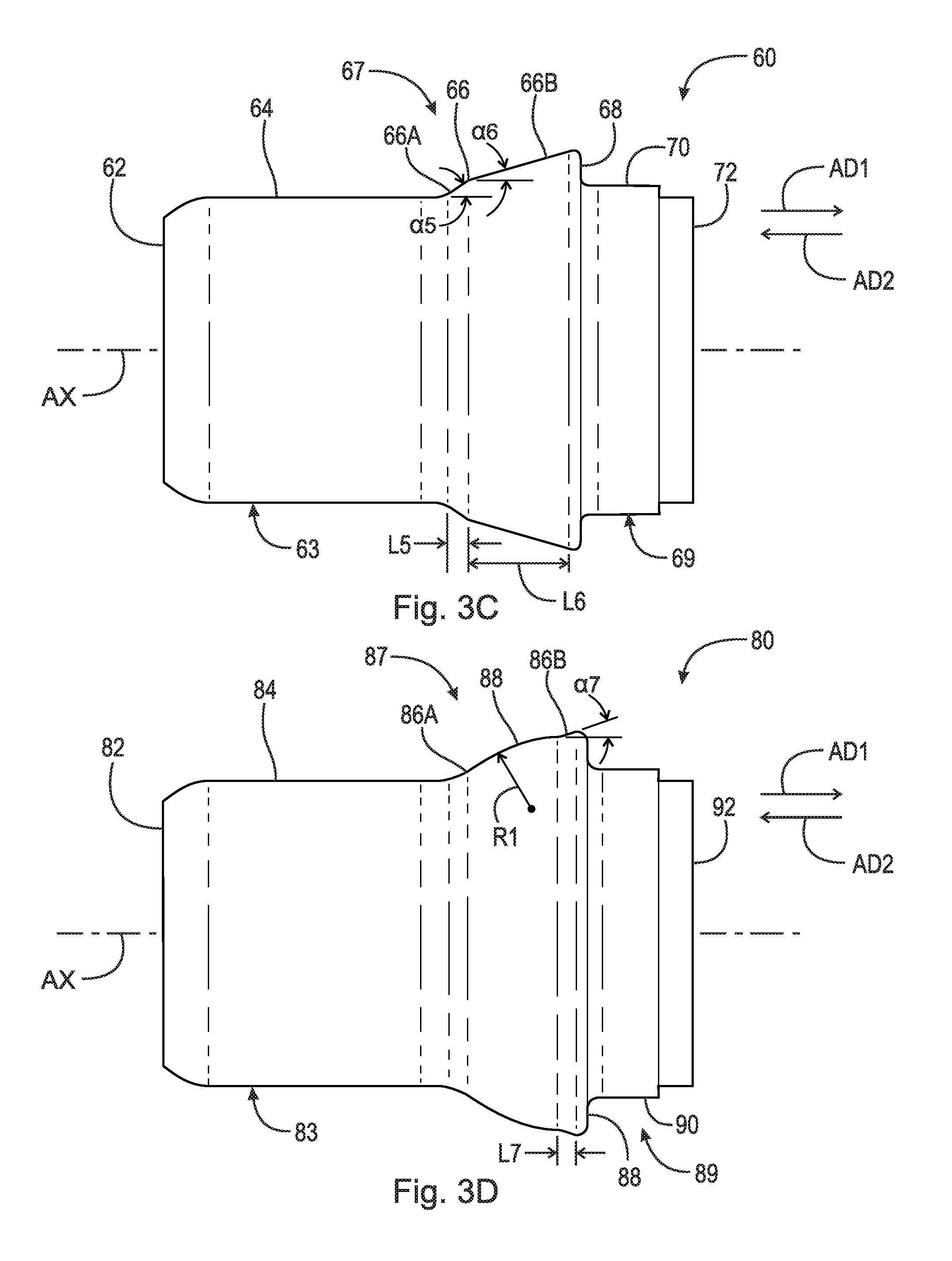
[0035] FIG. 3C is a side elevational view of tube end form 60. Tube end form 60 is generally cylindrical and comprises end 62, section 63, shoulder 67, section 69, and end 72. Section 63 is arranged between end 62 and shoulder 67 and comprises radially outward facing surface 64. Radially outward facing surface 64 includes a substantially constant diameter. In an example embodiment, radially outward facing surface 64 includes a variable diameter. Shoulder 67 is arranged between section 63 and section 69 and comprises radially outward facing surface 66. Section 69 is arranged between shoulder 67 and end 72 and comprises radially outward facing surface 70. Radially outward facing surface 70 includes a substantially constant diameter. In an example embodiment, radially outward facing surface 70 includes a variable diameter. Shoulder 67 is connected to radially outward facing surface 70 via shoulder surface 68. In an example embodiment, the diameter of radially outward facing surface 64 is equal to the diameter of radially outward facing surface 70. In an example embodiment, the diameter of radially outward facing surface 64 is not equal to the diameter of radially outward facing surface 70.
[0036] Radially outward facing surface 66 is generally a non-linear conical shape and increases in diameter in axial direction AD1. Radially outward facing surface 66 includes conical surface 66A and conical surface 66B. Conical surface 66A is arranged at angle .alpha.5 relative to horizontal axis AX, and has an adjacent side dimension of length L5. Conical surface 66B is arranged at angle .alpha.6 relative to horizontal axis AX, and has an adjacent side dimension of length L6. In the embodiment shown, angle .alpha.5 is not equal to .alpha.6 and length L5 is not equal to L6. In an example embodiment, .alpha.1 is 35.degree. and .alpha.2 is 10.degree.. It should be appreciated, that L5 is less than L3. In an example embodiment, radially outward facing surface 66 may comprise three or more conical surfaces.
[0037] FIG. 3D is a side elevational view of tube end form 80. Tube end form 80 is generally cylindrical and comprises end 82, section 83, shoulder 87, section 89, and end 92. Section 83 is arranged between end 82 and shoulder 87 and comprises radially outward facing surface 84. Radially outward facing surface 84 includes a substantially constant diameter. In an example embodiment, radially outward facing surface 84 includes a variable diameter. Shoulder 87 is arranged between section 83 and section 89 and comprises radially outward facing surface 86. Section 89 is arranged between shoulder 87 and end 92 and comprises radially outward facing surface 90. Radially outward facing surface 90 includes a substantially constant diameter. In an example embodiment, radially outward facing surface 90 includes a variable diameter. Shoulder 87 is connected to radially outward facing surface 90 via shoulder surface 88. In an example embodiment, the diameter of radially outward facing surface 84 is equal to the diameter of radially outward facing surface 90. In an example embodiment, the diameter of radially outward facing surface 84 is not equal to the diameter of radially outward facing surface 90.
[0038] Radially outward facing surface 86 is generally a non-linear conical shape and increases in diameter in axial direction AD1. Radially outward facing surface 86 includes arcuate surface 86A and conical surface 86B. Arcuate surface 86A is arranged between radially outward facing surface 84 and conical surface 86B, and comprises radius R1. Conical surface 86B is arranged at angle .alpha.7 relative to horizontal axis AX, and has an adjacent side dimension of length L7. In an example embodiment, radially outward facing surface 86 may comprise three or more surfaces.
[0039] FIG. 4A is a cross-sectional view of fluid connector 100 taken generally along line 4-4 in FIG. 2A, with tube end form 20 being inserted therein. It should be appreciated that the following discussion also applies to tube end forms 40, 60, and 80. End 22 is inserted into section 101 of fluid connector 100 as shown.
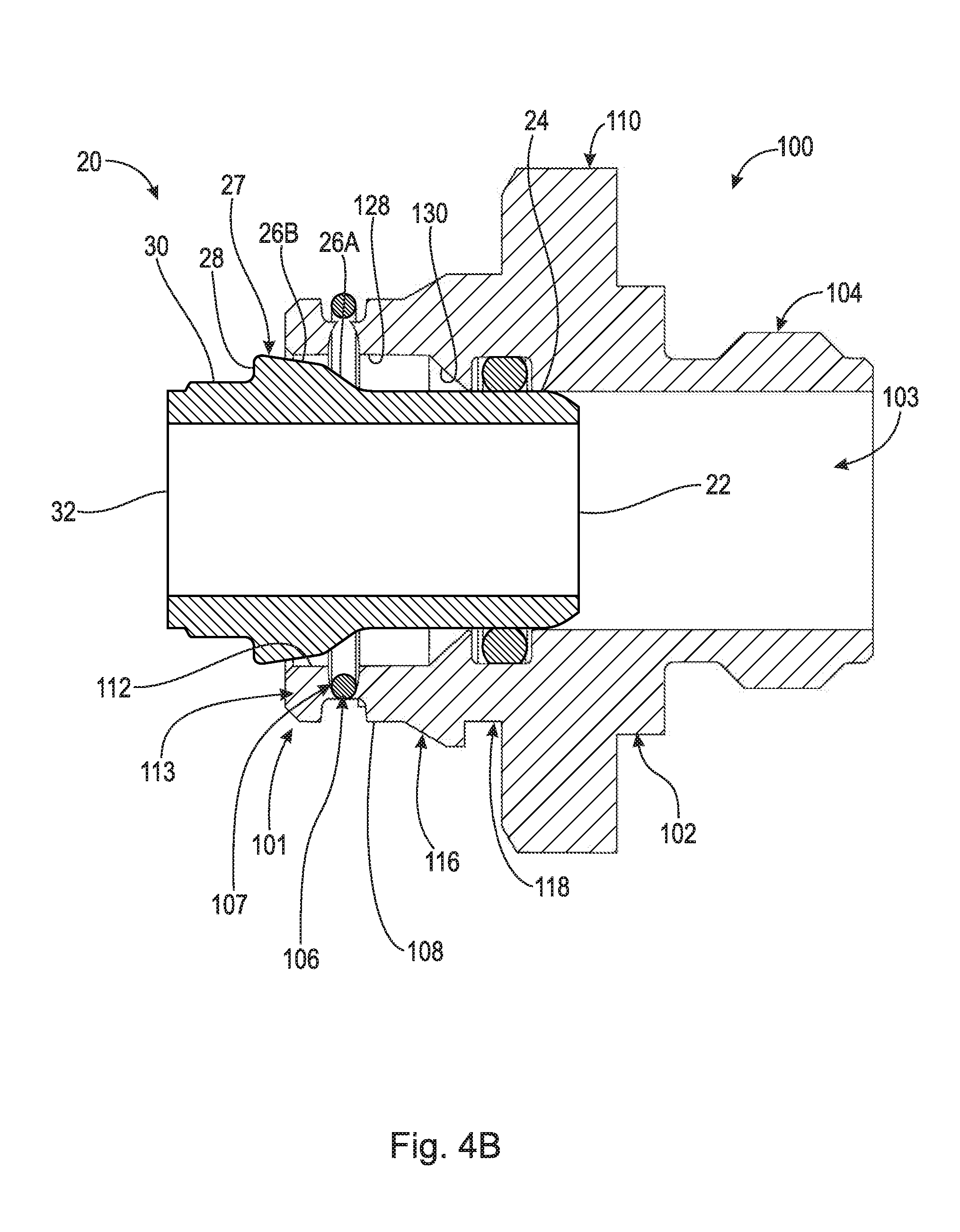
[0040] FIG. 4B is a cross-sectional view of fluid connector 100 shown in FIG. 4A with tube end form 20 being inserted therein. In FIG. 4B, tube end form 20 is further advanced within fluid connector 100 such that conical surface 26A is in contact with snap ring 106. At this point the required insertion force increases significantly, and as tube end form 20 is advanced within fluid connector 100, snap ring 106 expands radially outward.
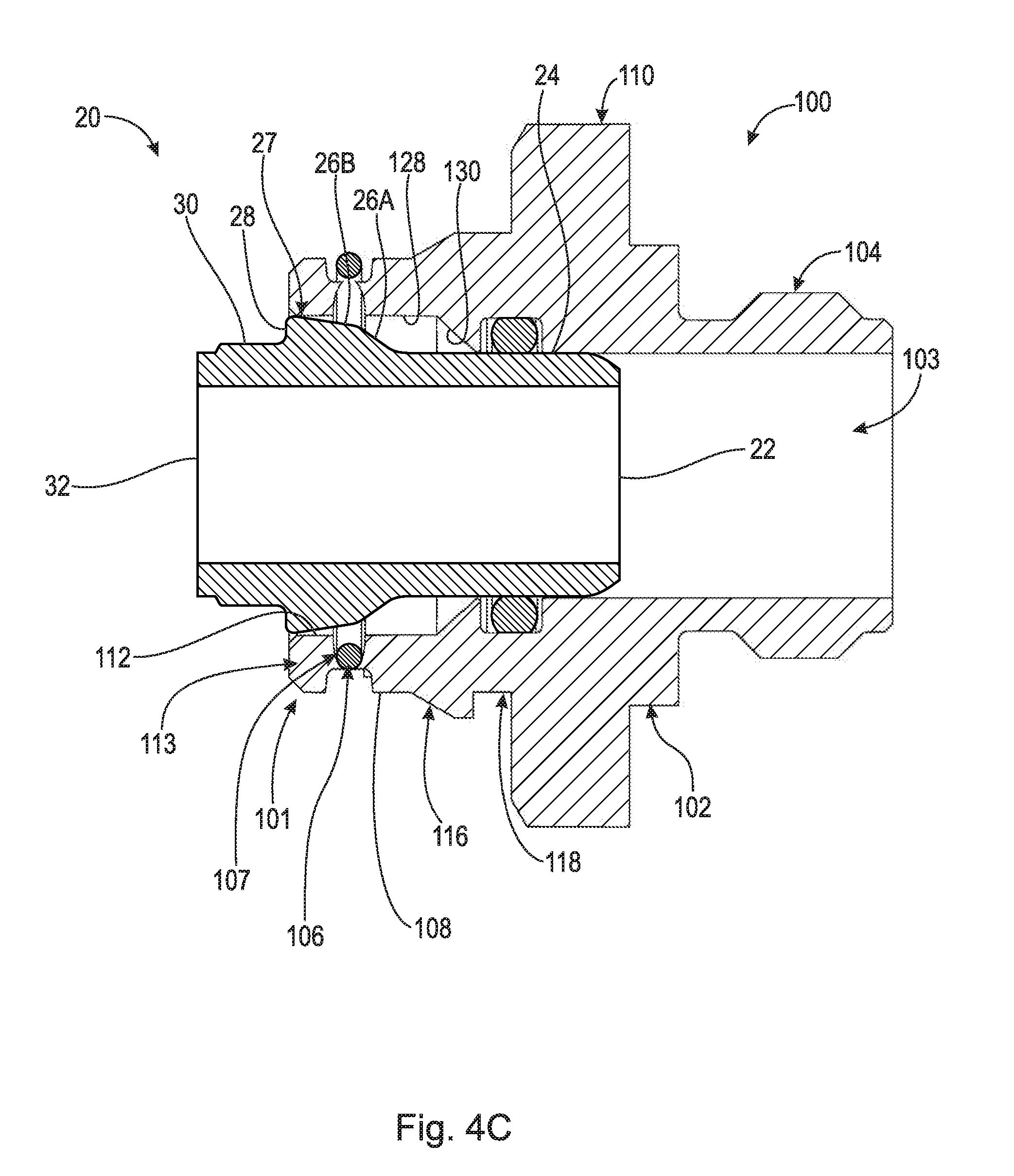
[0041] FIG. 4C is a cross-sectional view of fluid connector 100 shown in FIG. 4A with tube end form 20 being inserted therein. In FIG. 4C, tube end form 20 is further advanced within fluid connector 100 such that conical surface 26B is in contact with snap ring 106. The required insertion force may increase slightly, or decrease, upon crossing the threshold from conical surface 26A to conical surface 26B. Once snap ring 106 is in contact with conical surface 26B the required insertion force increases only slightly, because the angle of 26B, .alpha.2, is less than the angle of 26A, .alpha.1. As tube end form 20 is advanced within fluid connector 100, snap ring 106 expands radially outward.
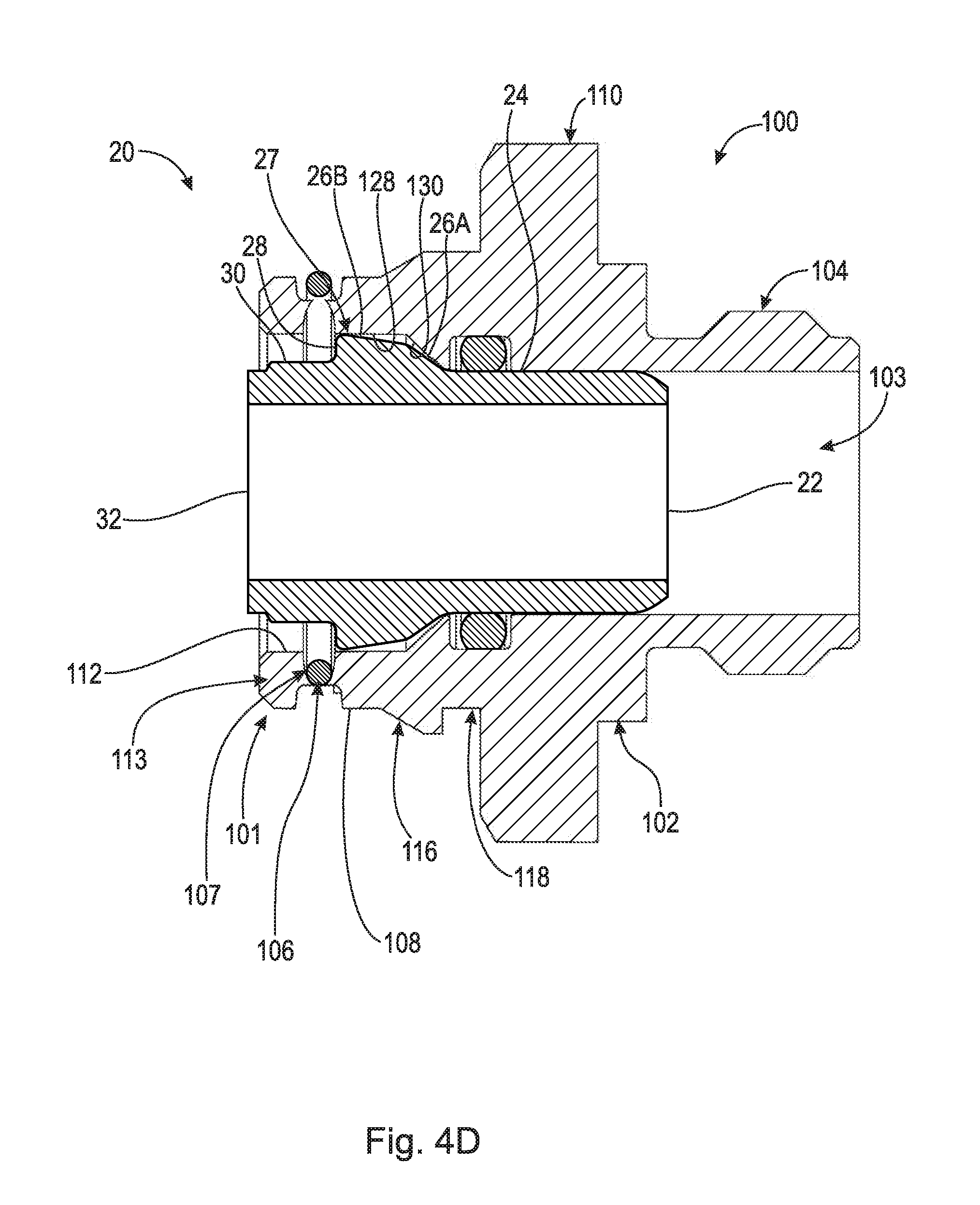
[0042] FIG. 4D is a cross-sectional view of fluid connector 100 shown in FIG. 4A with tube end form 20 fully inserted therein. In FIG. 4D, tube end form 20 is completely seated within fluid connector 100 such that snap ring 106 clears shoulder 27. Snap ring 106 contracts radially inward and may contact radially outward facing surface 30, and shoulder surface 28. Conical surface 26A may contact radially inward facing surface 130. Tube end form 20 is prevented from axial movement in a first axial direction by radially inward facing surface 130 and a second axial direction by snap ring 106.
[0043] It will be appreciated that various aspects of the disclosure above and other features and functions, or alternatives thereof, may be desirably combined into many other different systems or applications. Various presently unforeseen or unanticipated alternatives, modifications, variations, or improvements therein may be subsequently made by those skilled in the art which are also intended to be encompassed by the following claims.
REFERENCE NUMERALS
[0044] 20 Tube end form [0045] 21 Through-bore [0046] 22 End [0047] 23 Section [0048] 24 Radially outward facing surface [0049] 26 Radially outward facing surface [0050] 26A Conical surface [0051] 26B Conical surface [0052] 27 Shoulder [0053] 28 Shoulder surface [0054] 29 Section [0055] 30 Radially outward facing surface [0056] 32 End [0057] 32 Tube end form [0058] 40 End [0059] 43 Section [0060] 44 Radially outward facing surface [0061] 46 Radially outward facing surface [0062] 46A Conical surface [0063] 46B Conical surface [0064] 47 Shoulder [0065] 48 Shoulder surface [0066] 49 Section [0067] 50 Radially outward facing surface [0068] 52 End [0069] 60 Tube end form [0070] 62 End [0071] 63 Section [0072] 64 Radially outward facing surface [0073] 66 Radially outward facing surface [0074] 66A Conical surface [0075] 66B Conical surface [0076] 67 Shoulder [0077] 68 Shoulder surface [0078] 69 Section [0079] 70 Radially outward facing surface [0080] 72 End [0081] 80 Tube end form [0082] 82 End [0083] 83 Section [0084] 84 Radially outward facing surface [0085] 86 Radially outward facing surface [0086] 86A Arcuate surface [0087] 86B Conical surface [0088] 87 Shoulder [0089] 88 Shoulder surface [0090] 89 Section [0091] 90 Radially outward facing surface [0092] 92 End [0093] 100 Fluid connector [0094] 101 Section [0095] 102 Section [0096] 103 Through-bore [0097] 104 Threads [0098] 106 Snap ring [0099] 107 Apertures [0100] 108 Surface [0101] 110 Head [0102] 112 Inner surface [0103] 113 Shoulder [0104] 114 Shoulder surface [0105] 116 Shoulder [0106] 118 Channel [0107] 128 Radially inward facing surface [0108] 130 Radially inward facing surface [0109] 220 Tube end form [0110] 222 End [0111] 224 Radially outward facing surface [0112] 226 Radially outward facing surface [0113] 228 Shoulder surface [0114] 230 Radially outward facing surface [0115] 232 End [0116] L1 Length [0117] L2 Length [0118] L3 Length [0119] L4 Length [0120] L5 Length [0121] L6 Length [0122] L7 Length [0123] .alpha.1 Angle [0124] .alpha.2 Angle [0125] .alpha.3 Angle [0126] .alpha.4 Angle [0127] .alpha.5 Angle [0128] .alpha.6 Angle [0129] .alpha.7 Angle [0130] Angle [0131] R1 Radius [0132] AD1 Axial direction [0133] AD2 Axial direction
* * * * *
D00000
D00001
D00002
D00003
D00004
D00005
D00006
D00007
D00008
D00009
D00010
XML
uspto.report is an independent third-party trademark research tool that is not affiliated, endorsed, or sponsored by the United States Patent and Trademark Office (USPTO) or any other governmental organization. The information provided by uspto.report is based on publicly available data at the time of writing and is intended for informational purposes only.
While we strive to provide accurate and up-to-date information, we do not guarantee the accuracy, completeness, reliability, or suitability of the information displayed on this site. The use of this site is at your own risk. Any reliance you place on such information is therefore strictly at your own risk.
All official trademark data, including owner information, should be verified by visiting the official USPTO website at www.uspto.gov. This site is not intended to replace professional legal advice and should not be used as a substitute for consulting with a legal professional who is knowledgeable about trademark law.