Scroll Compressor
IIJIMA; Ryota ; et al.
U.S. patent application number 16/088931 was filed with the patent office on 2019-05-02 for scroll compressor. The applicant listed for this patent is HITACHI-JOHNSON CONTROLS AIR CONDITIONING, INC.. Invention is credited to Ryota IIJIMA, Kazumi TAMURA.
| Application Number | 20190128266 16/088931 |
| Document ID | / |
| Family ID | 62146382 |
| Filed Date | 2019-05-02 |


View All Diagrams
| United States Patent Application | 20190128266 |
| Kind Code | A1 |
| IIJIMA; Ryota ; et al. | May 2, 2019 |
SCROLL COMPRESSOR
Abstract
A scroll compressor has: a revolving scroll; a fixed scroll; a compression chamber that is defined by the revolving scroll and the fixed scroll to compress a working fluid; a suction chamber that is defined by the revolving scroll and the fixed scroll to suck the compressed working fluid; an electric motor that drives the revolving scroll; a bypass mechanism that communicates or shuts off between the compression chamber and the suction chamber; and a sealed vessel, wherein the bypass mechanism has: a bypass port that is formed in the fixed scroll and communicates between the compression chamber and the suction chamber; and a bypass valve that opens and closes the bypass port, and wherein a groove is formed in the revolving lap to communicate between the bypass port and a suction pressure space when the bypass port is open.
| Inventors: | IIJIMA; Ryota; (Tokyo, JP) ; TAMURA; Kazumi; (Tokyo, JP) | ||||||||||
| Applicant: |
|
||||||||||
|---|---|---|---|---|---|---|---|---|---|---|---|
| Family ID: | 62146382 | ||||||||||
| Appl. No.: | 16/088931 | ||||||||||
| Filed: | November 6, 2017 | ||||||||||
| PCT Filed: | November 6, 2017 | ||||||||||
| PCT NO: | PCT/JP2017/039892 | ||||||||||
| 371 Date: | September 27, 2018 |
| Current U.S. Class: | 1/1 |
| Current CPC Class: | F04C 29/0085 20130101; F04C 18/0215 20130101; F04C 18/0223 20130101; F04C 28/26 20130101; F04C 18/0284 20130101; F04C 18/02 20130101; F04C 29/12 20130101 |
| International Class: | F04C 29/12 20060101 F04C029/12; F04C 18/02 20060101 F04C018/02; F04C 29/00 20060101 F04C029/00 |
Foreign Application Data
| Date | Code | Application Number |
|---|---|---|
| Nov 21, 2016 | JP | 2016-226286 |
Claims
1. A scroll compressor comprising: a revolving scroll having a revolving lap; a fixed scroll having a fixed lap; a compression chamber that is a closed space defined by the revolving scroll and the fixed scroll to compress a working fluid; a suction chamber that is an open space defined by the revolving scroll and the fixed scroll to suck the compressed working fluid; an electric motor that drives the revolving scroll; a bypass mechanism that communicates or shuts off between the compression chamber and the suction chamber; and a sealed vessel that accommodates the revolving scroll, the fixed scroll, the compression chamber, the suction chamber, the electric motor and the bypass mechanism, wherein the bypass mechanism has: a bypass port that is formed in the fixed scroll and is capable of communicating between the compression chamber and the suction chamber; and a bypass valve that is capable of opening and closing the bypass port, and wherein a groove is formed in the revolving lap to communicate between the bypass port and a suction pressure space when the bypass port is open and the groove has a bottom surface, which is inclined outward and upward, at an end closer to a winding end of the revolving lap of the revolving scroll.
2. The scroll compressor according to claim 1, wherein the groove is a tooth-top groove in a concave shape.
3. The scroll compressor according to claim 1, the fixed scroll has a suction port through which the working fluid is sucked into the suction chamber, and a communication groove having a shape to communicate between the groove and the suction port on a lower surface of the fixed scroll.
4. (canceled)
5. The scroll compressor according to claim 1, the fixed scroll has a suction port through which the working fluid is sucked into the suction chamber; and the groove is formed to extend to the suction port.
6. The scroll compressor according to claim 1, wherein the revolving scroll has a tooth top, that is formed to reduce in height as it extends outward in a longitudinal direction of the revolving lap, at a winding end of the revolving lap.
7. The scroll compressor according to claim 1, an oil inlet hole is formed in the fixed scroll through which an oil is supplied, and the oil inlet hole is formed more downstream than an end at a downstream of the groove with respect to a flow of the working fluid.
Description
TECHNICAL FIELD
[0001] The present invention relates to a scroll compressor.
BACKGROUND ART
[0002] A scroll compressor has been known as a refrigerant compressor used in a refrigeration cycle such as for refrigeration or air-conditioning, or a gas compressor that compresses air or other gases. Further, a compressor having a volume control mechanism has been known to achieve high efficiency over a wide load range. For example, one of volume control methods frequently used for controlling the volume of the compressor is such that a frequency of a motor current in the compressor is changed with an inverter to electrically control a rotational speed.
[0003] However, if the rotational speed is extremely reduced, a leakage of the refrigerant in a compression chamber may be increased and motor efficiency may be decreased, to substantially reduce compressor efficiency. Further, in an extremely low speed region of the rotational speed, an oil film at a bearing is not retained due to oil viscosity, to cause bearing elements to directly contact a shaft, leading to burning or the like. To prevent these problems, a lower limit value is set for a practical rotational speed and a lower limit is also set for a volume control range.
[0004] To extend the volume control range more than the lower limit of the rotational speed control, some control methods for controlling an amount of a refrigerant have been considered, in which compression is operated by mechanically bypassing a part of the refrigerant from the refrigeration cycle.
[0005] For example, Patent Document 1 discloses "a scroll compressor comprising a compression mechanism in a casing, in which at least one of a first scroll member and a second scroll member, each having on its end plate a spiral lap to engage with each other, eccentrically rotates and a compression chamber is defined by the engaged laps between the inner surfaces of the end plates; and an operation volume control mechanism having an opening that is formed in the end plate of the first scroll member and communicates with the compression chambers, and a piston that opens and closes the opening, wherein the piston is formed based on a dimension tolerance with which a top surface protrudes more than an inner surface of the end plate of the first scroll member in a state of closing the opening, and, at least a top portion of the piston, which protrudes more than the inner surface of the end plate of the first scroll member in the state of closing the opening, is formed of a material having an abrasion resistance lower than that of the laps" (see Claim 1).
[0006] In the structure above, the bypass valve (piston) is opened at the time of volume control, to communicate between the compression chambers and a suction side of the compressor via a bypass port of the opening. This bypasses the refrigerant without being compressed and delays a compression timing, to reduce a discharge flow amount of the compressed refrigerant for controlling the volume.
PRIOR ART DOCUMENTS
Patent Documents
[0007] Patent Document 1: Japanese Patent Application Publication No. 2007-154762
SUMMARY OF THE INVENTION
Problem to be Solved by the Invention
[0008] However, in the scroll compressor disclosed in Patent Document 1, in a section where the lap of the second scroll member is in contact with the lap of the first scroll member at the position of the bypass port, the lap of the second scroll member positions at an end of the opening before the compression starts, to stop the communication between the compression chambers and the suction side. The refrigerant in the compression chambers is compressed during the time.
[0009] Accordingly, unnecessary compression power is generated before the compression starts and a loss due to excessive compression (see FIG. 13) occurs, to decrease efficiency. FIG. 13 shows a relationship between rotational angles of a conventional second scroll member and pressure in the compression chambers defined by the first scroll member and the second scroll member.
[0010] The present invention has been made in view of the above circumstances, and provides a scroll compressor that reduces a loss and has high efficiency over a wide operation range.
Solution to Problem
[0011] To solve the problem above, the present invention provides a scroll compressor including: a revolving scroll having a revolving lap; a fixed scroll having a fixed lap; a compression chamber that is a closed space defined by the revolving scroll and the fixed scroll to compress a working fluid; a suction chamber that is an open space defined by the revolving scroll and the fixed scroll to suck the compressed working fluid; an electric motor that drives the revolving scroll; a bypass mechanism that communicates or shuts off between the compression chamber and the suction chamber; and a sealed vessel that accommodates the revolving scroll, the fixed scroll, the compression chamber, the suction chamber, the electric motor and the bypass mechanism, wherein the bypass mechanism has: a bypass port that is formed in the fixed scroll and is capable of communicating between the compression chamber and the suction chamber; and a bypass valve that is capable of opening and closing the bypass port, and wherein a groove is formed in the revolving lap to communicate between the bypass port and a suction pressure space when the bypass port is open and the groove has a bottom surface, which is inclined outward and upward, at an end closer to a winding end of the revolving lap of the revolving scroll.
Advantageous Effects of the Invention
[0012] According to the present invention, a scroll compressor is provided that reduces a loss and has high efficiency over a wide operation range.
BRIEF DESCRIPTION OF THE DRAWINGS
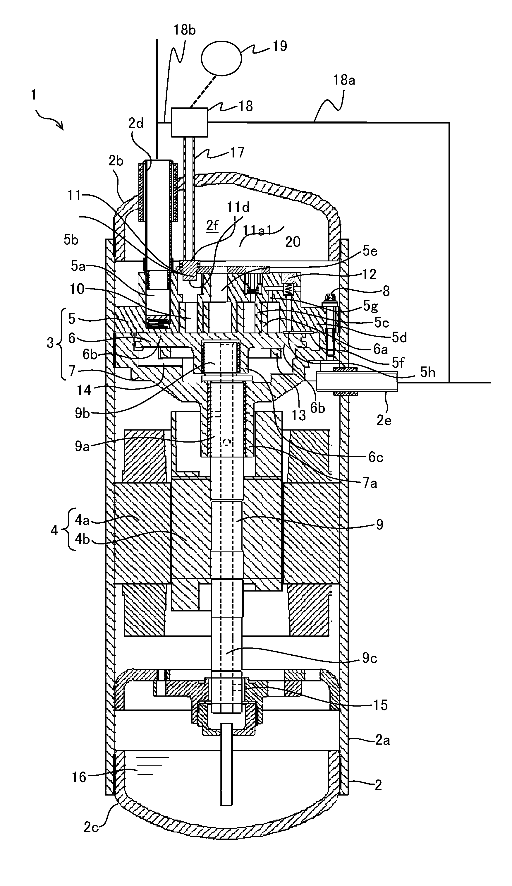
[0013] FIG. 1 is a vertical cross-sectional view of a compressor according to a first embodiment of the present invention;
[0014] FIG. 2 is a vertical cross-sectional view of an enlarged compression mechanical section of the compressor shown in FIG. 1;
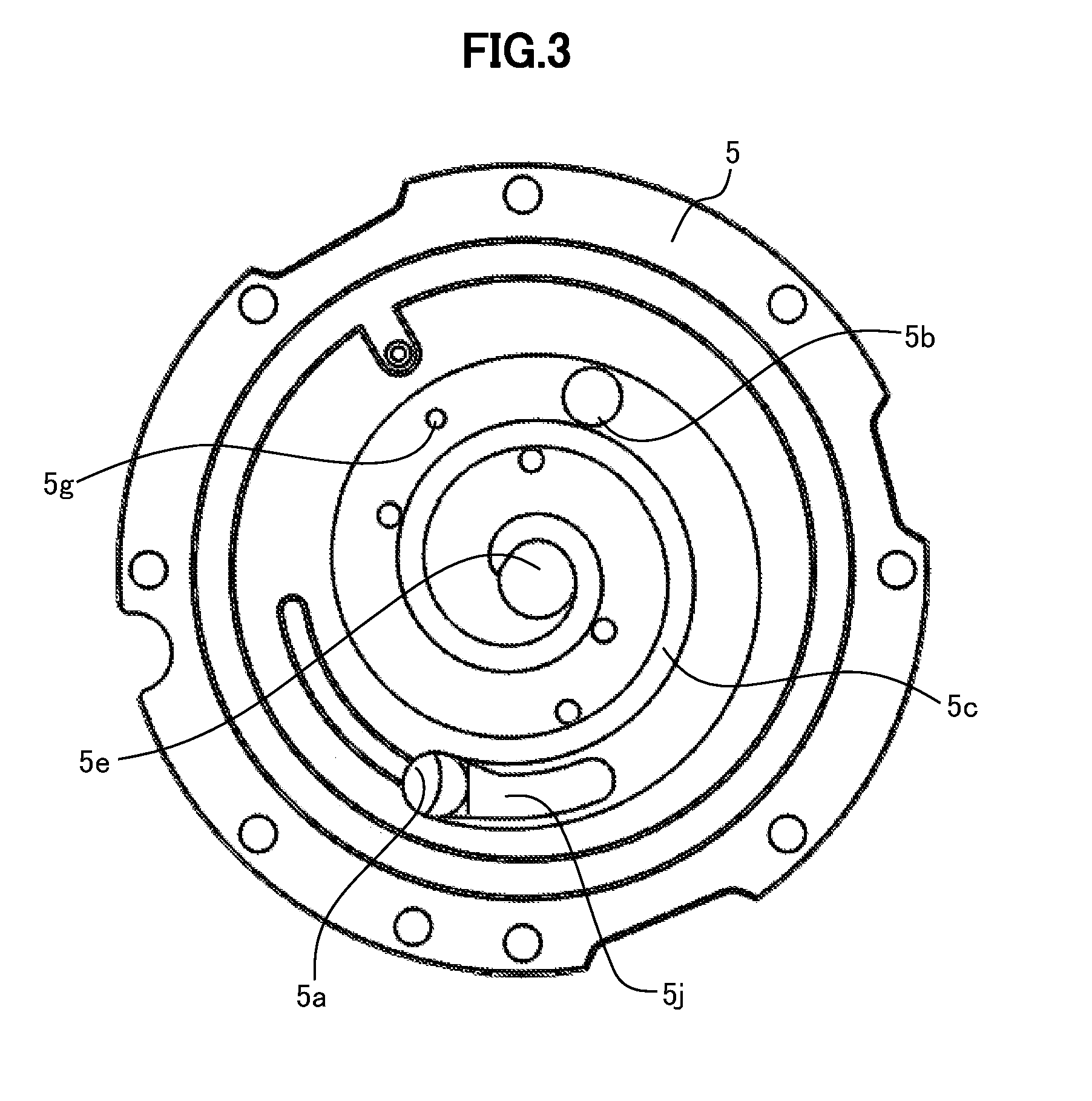
[0015] FIG. 3 is a bottom view of a fixed scroll of the compressor according to the first embodiment;
[0016] FIG. 4 is a top view of a revolving scroll of the compressor according to the first embodiment;
[0017] FIG. 5 is a cross-sectional view taken along a line I-I in FIG. 4;
[0018] FIG. 6 is a vertical cross-sectional view of the fixed scroll and the revolving scroll along a center line of a tooth-top groove;
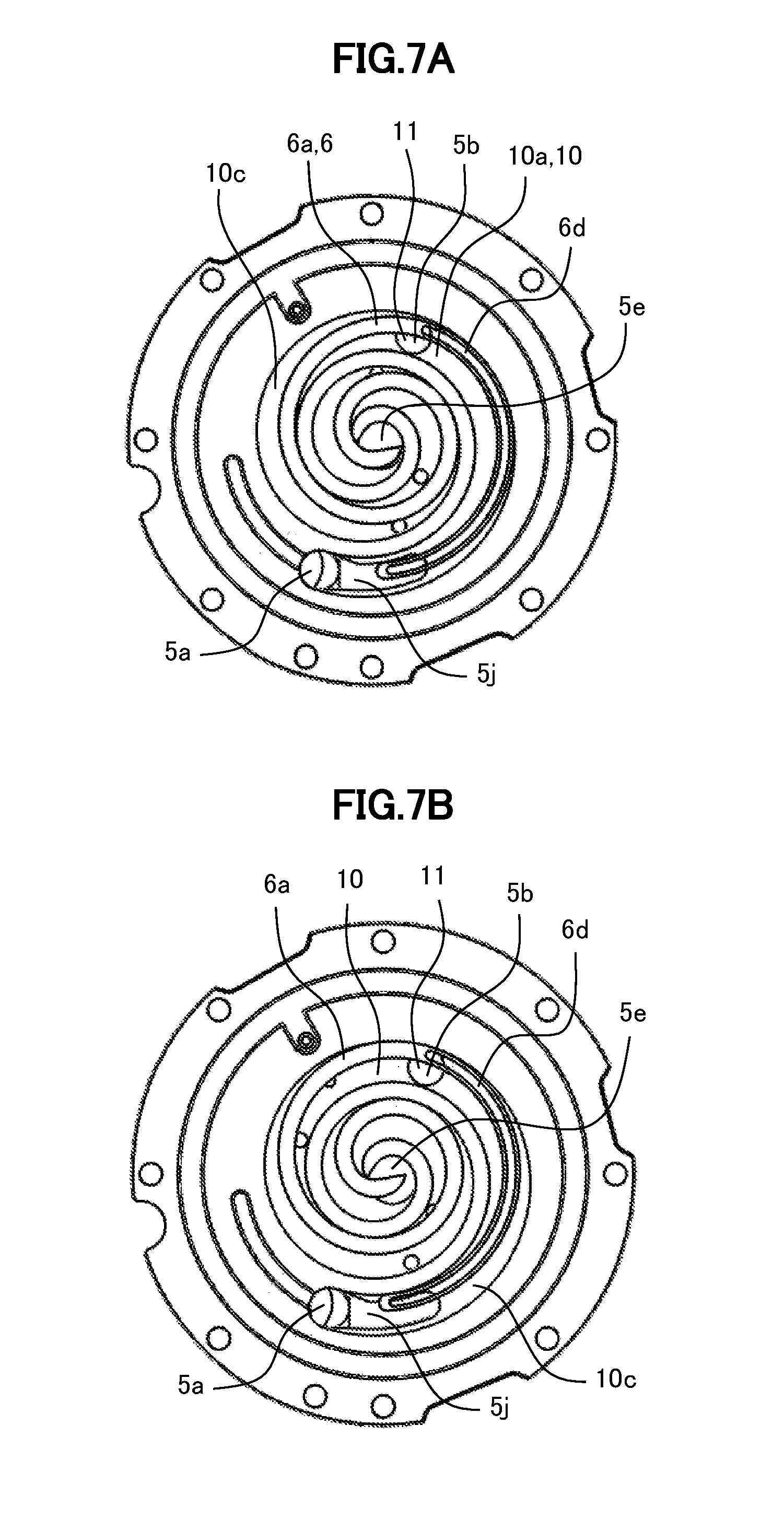
[0019] FIG. 7A is a bottom view of the compression chamber and a suction chamber to show a positional relationship between the compression chamber, a bypass port and the tooth-top groove in the compressor according to the first embodiment;
[0020] FIG. 7B is a bottom view of the compression chamber and a suction chamber to show a positional relationship between the compression chamber, a bypass port and the tooth-top groove in the compressor according to the first embodiment;
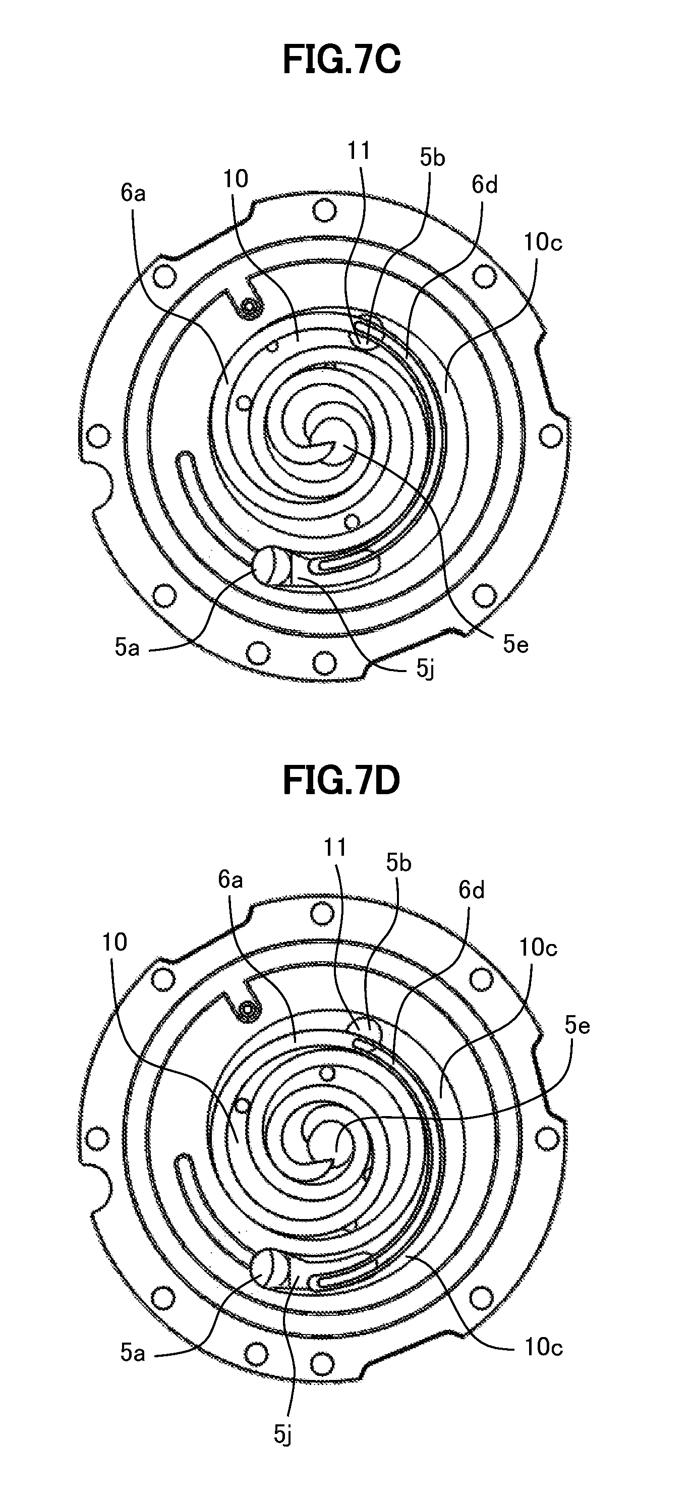
[0021] FIG. 7C is a bottom view of the compression chamber and a suction chamber to show a positional relationship between the compression chamber, a bypass port and the tooth-top groove in the compressor according to the first embodiment;
[0022] FIG. 7D is a bottom view of the compression chamber and a suction chamber to show a positional relationship between the compression chamber, a bypass port and the tooth-top groove in the compressor according to the first embodiment;
[0023] FIG. 8 is a vertical cross-sectional view of the fixed scroll and the revolving scroll along the center line of the tooth-top groove at a time of partial load operation in the compressor according to the first embodiment;
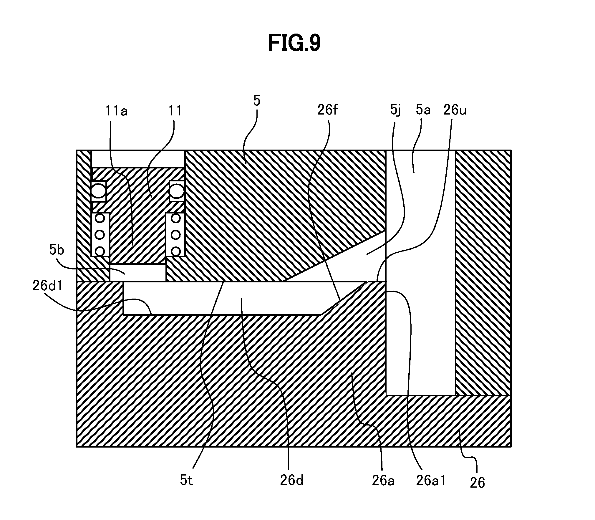
[0024] FIG. 9 is a vertical cross-sectional view of a fixed scroll and a revolving scroll along a center line of a tooth-top groove in a compressor according to a second embodiment;
[0025] FIG. 10 is a vertical cross-sectional view of a fixed scroll and a revolving scroll along a center line of a tooth-top groove in a compressor according to a third embodiment;
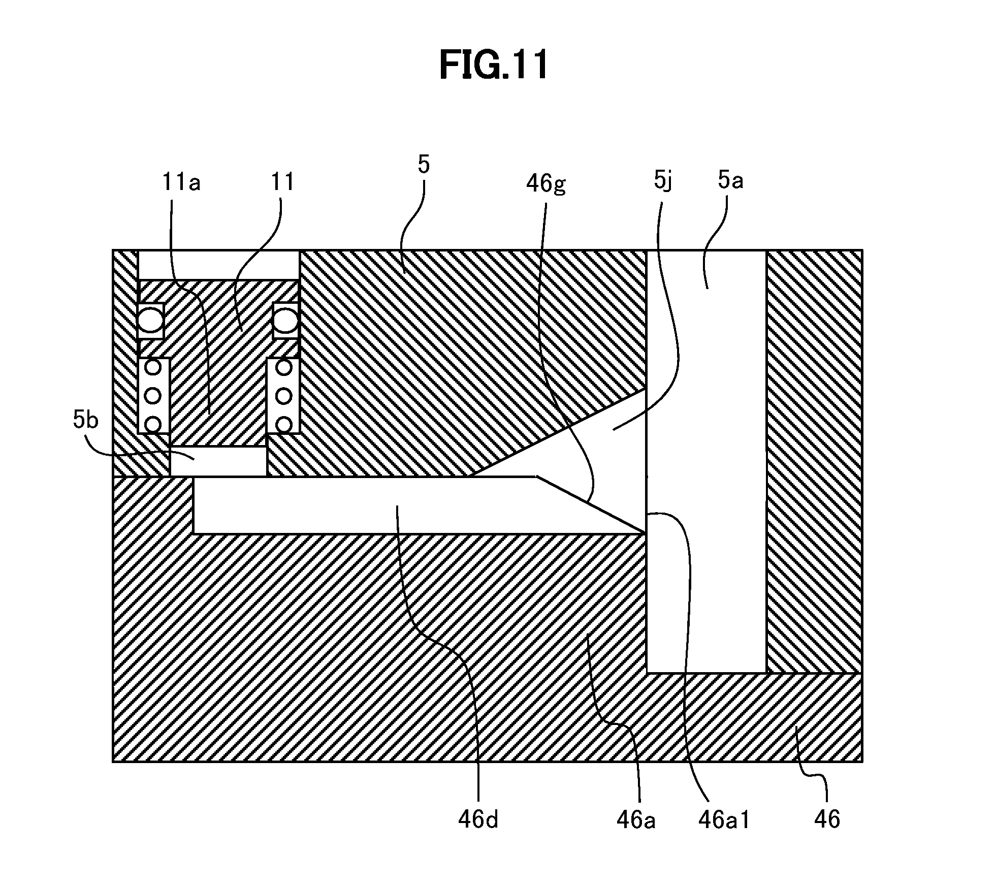
[0026] FIG. 11 is a vertical cross-sectional view of a fixed scroll and a revolving scroll along a center line of a tooth-top groove in a compressor according to a fourth embodiment;
[0027] FIG. 12 is a bottom view of a fixed scroll and a revolving scroll in horizontal cross section in the compressor according to a fifth embodiment; and
[0028] FIG. 13 is a chart showing a relationship between a rotational angle of a conventional second scroll and a pressure in a compressor chamber defined by a first scroll member and the second scroll member.
DETAILED DESCRIPTION OF THE PREFERRED EMBODIMENTS
[0029] A description will be given in detail of an embodiment of the present invention with reference to the drawings as appropriate. Note that, in the drawings below, the same members are denoted with the same reference numerals, and duplicate descriptions are omitted.
First Embodiment
[0030] FIGS. 1 to 5 show a structure of a compressor 1 according to a first embodiment.
[0031] FIG. 1 is a vertical cross-sectional view of the compressor 1 according to the first embodiment of the present invention.
[0032] FIG. 2 is an enlarged vertical cross-sectional view of a compression mechanical section 3 of the compressor 1 in FIG. 1.
[0033] The compressor 1 according to the first embodiment is a scroll compressor.
[0034] The compressor 1 controls a volume by switching between a full load operation in which a gas refrigerant (working fluid) supplied from a suction port 5a is compressed in the compression mechanical section 3 and a partial load operation in which a part of the gas refrigerant is compressed.
[0035] In the partial load operation, the part of the gas refrigerant is bypassed to a suction side and the remaining gas refrigerant is compressed in a compression chamber 10.
[0036] The compressor 1 has the compression mechanical section 3 for compressing the gas refrigerant (hereinafter, referred to as refrigerant), an electric motor 4 as drive source of the compression mechanical section 3, a sealed vessel 2 for accommodating the compression mechanical section 3, the electric motor 4 and the like, and a control unit (18, 19).
[0037] FIG. 3 is a bottom view of a fixed scroll 5 of the compressor 1 according to the first embodiment. FIG. 4 is a top view of a revolving scroll 6 of the compressor 1 according to the first embodiment. FIG. 5 is a cross-sectional view taken along an I-I line in FIG. 4.
[0038] The compression mechanical section 3 has the fixed scroll 5 having a spiral lap 5c which is vertically arranged at a lower portion and the revolving scroll 6 having a spiral lap 6a which is vertically arranged at an upper portion. The revolving scroll 6 is arranged under the fixed scroll 5.
[0039] The sealed vessel 2 has a case 2a in a cylindrical shape that is vertically arranged in the middle, a lid chamber 2b at the top and a bottom chamber 2c at the bottom that are welded to the case 2a.
[0040] The compression mechanical section 3 is arranged in an upper part of the sealed vessel 2, and the electric motor 4 is arranged at a lower part via a crankshaft 9. A lubricant 16 is accumulated in the bottom of the sealed vessel 2. The lubricant 16 is supplied to the mechanical section via an oil supply passage 9c of the crankshaft 9.
[0041] A suction pipe 2d to suck the refrigerant to be compressed is arranged through the lid chamber 2b at the top. As shown in FIG. 1, a suction port 5a connected to the suction pipe 2d is formed in the fixed scroll 5. The suction port 5a is used to suck the refrigerant to be compressed, and is arranged coaxially with the suction pipe 2d.
[0042] A discharge port 5e that communicates between the compression chamber 10 and the other side (upper side) of the fixed scroll 5 from the lap is defined approximately at the center of a base plate 5d of the fixed scroll 5. The discharge port 5e is used to discharge the refrigerant compressed in the compression mechanical section 3.
[0043] The sealed vessel 2 defines therein a discharge pressure chamber 2f from which the refrigerant compressed in the compression mechanical section 3 is discharged. A discharge pipe 2e through which the compressed refrigerant is discharged is arranged through a side surface of the centrally located case 2a.
<Compression Mechanical Section 3>
[0044] The compression mechanical section 3 has the fixed scroll 5 in the upper part, the revolving scroll 6 under the fixed scroll 5, and a frame 7 that supports the revolving scroll 6 from below.
[0045] As shown in FIG. 2, the fixed scroll 5 has the spiral lap 5c extending downward toward an end plate 5f of the base plate 5d as a main body.
[0046] The revolving scroll 6 has, as with the fixed scroll 5, the spiral lap 6a extending upward on a base plate 6b as a main body.
[0047] The frame 7 is integrally fixed to the fixed scroll 5 by a bolt 8, and slidably supports the revolving scroll 6 from below.
[0048] The spiral lap 5c of the fixed scroll 5 is engaged with the spiral lap 6a of the revolving scroll 6 to define the compression chamber 10 so as to compress the refrigerant. The compression chamber 10 is a closed space between the fixed scroll 5 and the revolving scroll 6. Further, the spiral lap 5c of the fixed scroll 5 is engaged with the spiral lap 6a of the revolving scroll 6 to define a suction chamber 10a (see FIG. 7A). The suction chamber 10a is defined by the fixed scroll 5 and the revolving scroll 6, and serves as a communication space with the suction port 5a.
<Bypass Port 5b>
[0049] As shown in FIG. 2, a bypass port 5b is defined in the base plate 5d of the fixed scroll 5 to penetrate from the compression chamber 10 to the other side (upper side) of the fixed scroll 5. The bypass port 5b is used for volume control, to be fully closed at the time of full load operation and to be opened at the time of partial load operation. That is, at the time of full load operation, a bypass valve 11 fills in a gap g1 of the bypass port 5b to close a communication between the compression chamber 10 and the suction chamber 10a, and, at the time of partial load operation, the compression chamber 10 is communicated with the suction chamber 10a via the gap g1 of the bypass port 5b (see FIG. 2).
[0050] Thus, the amount of refrigerant to be compressed is adjusted to control an output of the compressor 1.
[0051] The bypass port 5b is formed, for example, with two coaxial cylindrical grooves, each having a different diameter, in communication with each other. As shown in FIG. 2, the bypass port 5b has a cylindrical groove 5b1 on the other (upper) side from the lap and a cylindrical groove 5b2 on the lower lap 6c side, the former having a larger diameter than the latter.
[0052] The diameter of the cylindrical groove 5b2 on the lower lap side of the bypass port 5b only needs to be larger than a thickness t2 of the lap 6a of the revolving scroll 6. That is, an opening of the cylindrical groove 5b2 on the lap side only needs to be defined over the lap 6a of the revolving scroll 6.
[0053] As shown in FIG. 4, the revolving scroll 6 has a tooth-top groove 6d in an concave shape partially arranged along a spiral shape of the lap 6a in the center of a tooth top of the spiral lap 6a facing the fixed scroll 5.
[0054] The tooth-top groove 6d has a width t1 narrower than the thickness t2 of the lap 6a, and, one end thereof is a winding start of the lap 6a and is formed at a position to communicate with the bypass port 5b (see FIGS. 7A to 7D). FIG. 6 is a vertical cross-sectional view of the fixed scroll 5 and the revolving scroll 6 along a center line of the tooth-top groove 6d.
[0055] The other end of the tooth-top groove 6d is a winding end 6a1 of the lap 6a and is formed at a position to communicate with an inclined groove 5j formed on the fixed scroll 5. The inclined groove 5j is formed to have a slope extending upward and outward from a tooth-top surface 5t of the fixed scroll 5 to the suction port 5a. The inclined groove 5j allows the tooth-top groove 6d to communicate with the suction port 5a.
[0056] The tooth-top groove 6d is formed to always communicate between the bypass port 5b and the suction side. The refrigerant flowing into the tooth-top groove 6d can be flown to the suction port 5a through the inclined groove 5j. Further, an advantageous effect can be obtained such that the lubricant 16 flowing into the inclined groove 5j is discharged outside.
[0057] Note that, though the cross section of the tooth-top groove 6d is in a rectangular shape in FIG. 6, the cross-sectional shape is not necessarily in a rectangular shape. For example, the tooth-top groove 6d may have a U-shaped cross section or a V-shaped cross section. The shape of the tooth-top groove 6d is not limited as long as the groove is in a concave shape. Further, the shape of the inclined groove 5j is not limited as long as it communicates between the tooth-top groove 6d and the suction port 5a.
<Bypass Valve 11>
[0058] The bypass valve 11 has a shape in which two coaxial cylinders, each having a different diameter, are connected, so as to be fitted in the bypass port 5b. As shown in FIG. 2, the bypass valve 11 is fitted into the bypass port 5b, in which a port insert 11a at a lower cylindrical portion having a smaller diameter than an upper cylindrical portion is oriented to the lap 5c side (lower side) of the fixed scroll 5.
[0059] A planar retainer 20 is attached on the other side of the fixed scroll 5 from the lap 5c. The retainer 20 prevents the bypass valve 11 from coming off the fixed scroll 5 outside because the bypass valve 11 abuts the retainer 20.
[0060] As shown in FIG. 2, at the time of full load operation, the bypass valve 11 does not come off the cylindrical groove 5b1 on the other side of the bypass port 5 from the lap even when the bypass valve 11 presses the revolving scroll 6.
[0061] Further, at the time of partial load operation, the bypass valve 11 does not come off the cylindrical groove 5b1 on the other side of the bypass port 5 from the lap even when the bypass valve 11 is away from the revolving scroll 6.
<Pressure Switching Device 18>
[0062] The pressure switching device 18 shown in FIG. 1 is mounted outside the sealed vessel 2, and communicates with a control pressure space 11d via a control pipe 17. Further, the pressure switching device 18 has a high pressure side channel 18a connected to the discharge pipe 2e for discharging the compressed refrigerant and a low pressure side channel 18b connected to the suction pipe 2d for the refrigerant before the compression.
[0063] Thus, the pressure switching device 18 can take the refrigerant under a low suction pressure and the refrigerant under a high discharge pressure, and selectively introduces one of the refrigerants at two pressure levels to the control pipe 17.
[0064] The refrigerant pressure introduced in the control pipe 17 is controlled to be switched at an arbitrary timing by the pressure switching device 18 with a signal from the pressure control device 19.
<Each Member>
[0065] The crank shaft 9 for revolving the revolving scroll 6 with the electric motor 4 is vertically extended at the center in the sealed vessel 2.
[0066] As shown in FIG. 1, the frame 7 fixed to the sealed vessel 2 has a main bearing 7a to rotatably support the crankshaft 9. A revolving bearing 6c is arranged, at a lower portion of the revolving scroll 6, to be coupled with an eccentric portion 9b of the crankshaft 9.
[0067] A back pressure chamber 14 is defined between the other side, on the lower side, of the revolving scroll 6 from the lap 6a and the frame 7. The revolving scroll 6 is pressed against the fixed scroll 5 from below by the back pressure of the back pressure chamber 14.
[0068] An Oldham ring 13 is arranged in the back pressure chamber 14. The Oldham ring 13 serves to cause the revolving scroll 6 to be revolved by receiving eccentric rotation of the eccentric portion 9b of the crankshaft 9, without the revolving scroll 6 being rotated.
[0069] The Oldham rings 13 are attached in a groove (not shown) formed on the other side (lower side) of the revolving scroll 6 from the lap 6a and a groove (not shown) formed on the upper center of the frame 7.
[0070] As shown in FIG. 2, in the fixed scroll 5, oil inlet holes 5g, 5h are formed to communicate between the back pressure chamber 14 and the compression chamber 10. A back pressure control valve 12 is arranged between the oil inlet holes 5g, 5h.
[0071] As shown in FIG. 1, the electric motor 4 has a stator 4a and a rotor 4b. The stator 4a is fixed to the sealed vessel 2 by press fitting, welding or the like. The rotor 4b has the crankshaft 9 fixed thereto and is rotatably supported in the stator 4a.
[0072] The crankshaft 9 includes a main shaft 9a and the eccentric portion 9b, and is supported by the upper main bearing 7a arranged in the frame 7 and a lower bearing 15 arranged in the sealed vessel 2. The eccentric portion 9b is formed integrally to be eccentric to the main shaft 9a of the crankshaft 9, and is fitted into the revolving bearing 6c formed in a lower portion of the revolving scroll 6. This allows the revolving scroll 6 to rotate with respect to the eccentric portion 9b.
[0073] The crankshaft 9 is rotatively driven by the electric motor 4. Then, the eccentric portion 9b of the crankshaft 9 is eccentrically rotates with respect to the main shaft 9a, to revolve the revolving scroll 6. Further, the crankshaft 9 has the oil supply passage 9c at the center, through which the lubricant 16 flows to the main bearing 7a of the frame 7, the lower bearing 15, and the revolving bearing 6c of the revolving scroll 6. The lubricant 16 supplied from the oil supply passage 9c (see FIG. 1) to the revolving bearing 6c flows through the back pressure chamber 14, the oil inlet holes 5h, 5g to the lap 5c of the fixed scroll 5 and the lap 6a of the revolving scroll 6 which define the compression chamber 10.
[0074] The compressor 1 switches the full load operation and the partial load operation to control the volume. In the full load operation, the bypass valve 11 is closed to compress the refrigerant sucked through the suction port 5a. In the partial load operation, the bypass valve 11 is opened to circulate a part of the refrigerant in the compression chamber 10 without being compressed to the suction side through the bypass port 5b and to cause the rest of the refrigerant to be compressed.
<Full Load Operation>
[0075] An operation of the full load operation with the closed bypass valve 11 will be described with reference to FIGS. 7A to 7D.
[0076] FIGS. 7A to 7D are bottom views of the compression chamber 10 and the suction chamber 10a, showing a relationship between the compression chamber 10, the bypass port 5b and the tooth-top groove 6d in the compressor 1 according to the first embodiment.
[0077] In the order of 7A, 7B, 7C and 7D, the rotation angle of the revolving scroll 6 increases.
[0078] When a refrigerant in high pressure is supplied from the pressure switching device 18 (see FIG. 1) to the control pressure space 11d and the bypass valve 11 is closed, the scroll compressor 1 operates in the full load operation. When the bypass valve is closed, the bypass port 5 shuts off the compression chamber 10 from suction chamber 10a.
[0079] When the revolving scroll 6 is revolved via the eccentric portion 9b of the crankshaft 9 driven by the electric motor 4, as shown in FIG. 1, the refrigerant flows from the suction pipe 2d through the suction port 5a of the fixed scroll 5 to the suction chamber 10a (see FIG. 7A) defined by the revolving scroll 6 and the fixed scroll 5. Here, the suction chamber 10a is shortly to be a closed space to form the compression chamber 10 (see FIG. 7B). As the refrigerant moves toward the center of the revolving scroll 6 and the fixed scroll 5, it is compressed because the compressor chamber 10 is reduced in volume (see FIGS. 7C, 7D). Note that the compression chamber 10 is formed, as described above, by the spiral lap 5c of the fixed scroll 5 and the spiral lap 6a of the revolving scroll 6 being engaged with each other.
[0080] At this stage, the port insert 11a of the bypass valve 11 fully closes the cylindrical groove 5b2 of the bypass port 5b facing the lap, and further, is brought in contact with an upper surface 6u1 (see FIG. 6) of the lap 6a of the revolving scroll 6.
[0081] As described above, the tooth-top groove 6d is formed in the tooth top of the lap 6a. As shown in FIGS. 7A to 7D, one end of the tooth-top groove 6d is positioned to face the lower portion of the bypass port 5b. However, as shown in FIG. 6, a front end surface (lower end surface) 11a1 of the port insert 11a of the bypass valve 11 is always in contact with the tooth top surface (upper surface 6u1 on the tooth top of the lap 6a) around the tooth-top groove 6d, to close the space between the compression chamber 10 and the tooth-top groove 6d. Accordingly, the flow of the refrigerant between the compression chamber 10 and the tooth-top groove 6d is shut off.
[0082] Accordingly, as shown in FIG. 6, when the bypass valve 11 is closed, in other words, when the port insert 11a of the bypass valve 11 presses to contact the upper surface 6u1 of the lap 6a of the revolving scroll 6, the refrigerant is prevented from leaking from the compression chamber 10 through the tooth-top groove 6d toward the suction side.
[0083] Further, when the port insert 11a of the bypass valve 11 contacts the lap 6a of the revolving scroll 6 from above, the compression chamber 10 is also shut off from the suction chamber 10a. Therefore, the refrigerant in the compression chamber 10 is compressed immediately after the suction has been completed. Then, the refrigerant compressed in the compression chamber 10 is discharged from the discharge port 5e (see FIG. 1) formed approximately at the center of the base plate 5d of the fixed scroll 5 to the discharge pressure chamber 2f. The refrigerant discharged to the discharge pressure chamber 2f flows outside through the discharge pipe 2e (see FIG. 1).
[0084] As described above, at the time of full load operation, a high efficient operation is executed similar to the compressor 1 without a volume control mechanism.
<Partial Load Operation>
[0085] Next, a behavior of the partial load operation with the opened bypass valve 11 will be described with reference to FIGS. 7A to 7D and FIG. 8.
[0086] Opening the bypass valve 11 means that the port insert 11a of the bypass valve 11 is separated from the upper surface 6u1 of the lap 6a of the revolving scroll 6, to communicate between the compression chamber 10 and the suction chamber 10a via the gap g1 of the bypass valve 11.
[0087] FIG. 8 is a vertical cross-sectional view of the fixed scroll 5 and the revolving scroll 6 taken along a center line of the tooth-top groove 6d during the partial load operation in the compressor 1 according to the first embodiment.
[0088] When the control pressure space 11d communicates with the suction pressure space through the low pressure side channel 18b and the pressure switching device 18 shown in FIG. 1, the pressure in the control pressure space 11d (see FIG. 2) is equal or less than the pressure in the compression chamber 10 that communicates with the bypass port 5b. Therefore, a gas load is not applied to close the bypass valve 11, that is, to move the bypass valve 11 shown in FIG. 1 downward.
[0089] Further, when a load (spring force) is applied to move the bypass valve 11 upward on the other side from the lap 6a by a spring 11c, the bypass valve 11 is separated from the revolving scroll 6 and is pressed upward to contact the retainer 20. Thus, the pressure chamber 10 communicates with the suction chamber 10a via the gap g1 of the bypass port 5b and the bypass port 5b is opened.
[0090] In this case, the compressor 1 executes the partial load operation to be described below.
[0091] Hereinafter, a description will given of a detailed operation of the partial load operation with reference to FIGS. 7A to 7D.
[0092] When the revolving scroll 6 is revolved via the eccentric portion 9b (see FIG. 2) of the crankshaft 9 driven by the electric motor 4, the refrigerant is flown through the suction pipe 2d and the suction port 5a into the suction chamber 10a (see FIG. 7A).
[0093] When the crankshaft 9 proceeds to be rotated, the suction chamber 10a is completely surrounded by the lap 5c of the fixed scroll 5 and lap 6a of the revolving scroll 6, to form the compression chamber 10. The refrigerant is compressed due to the reduction of the volume in the compression chamber 10.
[0094] However, at this moment, since the bypass port 5b is open, the compression chamber 10 is ideally in communication with the suction chamber 10c on an outer side, to bypass the refrigerant in the compression chamber 10 to the suction side, without being compressed. However, as can be seen in FIG. 7B, at this moment, the lap 6a of the revolving scroll 6 is in contact with the fixed scroll 5 on the bypass port 5b, and the bypass port 5b is not directly in communication with the suction chamber 10c.
[0095] In this case, a loss due to excessive compression shown in FIG. 13 could occur.
[0096] Therefore, tooth-top groove 6d described above is formed in the tooth top of the lap 6a of the revolving scroll 6 in the compressor 1.
[0097] As shown in FIG. 6, the tooth-top groove 6d is formed to communicate with the inclined groove 5j having the slope communicating with the suction port 5a (see FIGS. 7A to 7D), and always communicates between the bypass port 5b and the suction side with each other. Therefore, even at the moment shown in FIG. 7B, the refrigerant in the compression chamber 10 is bypassed to the suction side via the bypass port 5b and the tooth-top groove 6d. Accordingly, the tooth-top groove 6d, the inclined groove 5j and the suction port 5a prevent the refrigerant in the compression chamber 10 from being compressed. The state at that time is shown in FIG. 8. FIG. 8 is a vertical cross-sectional view taken along the center line of the tooth-top groove 6d. FIG. 8 shows the bypass port 5b in communication with the compression chamber 10 which is not shown in FIG. 8. Arrows al in FIG. 8 indicates the flow of the refrigerant.
[0098] As shown in FIG. 8, when the bypass valve 11 moves upward to be away from the upper surface 6u1 of the revolving scroll 6, the refrigerant in the compression chamber 10 flows through the gap g1 defined in the bypass port 5b, the tooth-top groove 6d of the lap 6a of the revolving scroll 6, the inclined groove 5j and the suction port 5a so as to be discharged to the suction side.
[0099] Then, as shown in FIG. 7C, the bypass port 5b begins to communicate with the suction chamber 10c. The refrigerant in the compression chamber 10 flows out via the two passages: the passage that bypasses the refrigerant from the bypass port 5b to the suction chamber 10c and the passage that bypasses the refrigerant from the bypass port 5b through the tooth-top groove 6d to the suction port 5a on the suction side (arrows al in FIG. 8).
[0100] When the rotation angle of the revolving scroll 6 further increases to the state shown in FIG. 7D, the compression chamber 10 is no longer in communication with the bypass port 5b. Accordingly, the compression chamber 10 forms the closed space by the lap 5c of the fixed scroll 5 and the lap 6a of the revolving scroll 6 to start compressing the refrigerant. Then, as in the case of the full load operation, the compressed refrigerant is discharged through the discharge port 5e to the discharge pressure chamber 2f and flows outside through the discharge pipe 2e.
[0101] In the partial load operation, as described above, the volume in the compression chamber 10 at the time of starting compression shown in FIG. 7C is smaller than that at the time of starting compression in the full load operation (see FIG. 7B). Therefore, the amount of compressed refrigerant to be discharged is reduced in the partial load operation, and an operation at lower load is executed, without the rotational speed being changed. Note that FIG. 7A to FIG. 7D illustrate the behaviors of the full load operation and the partial load operation in the compression chamber 10 on the inner side of the lap 6a of the revolving scroll 6, but exactly the same behaviors hold true in the compression chamber 10 on the outer side of the lap 6a.
[0102] As described above, the high efficient compressor 1 over a wide operation range is provided, without generating a loss due to excessive compression, by using an appropriate rotational speed according to the state of the mechanical volume control.
Second Embodiment
[0103] FIG. 9 is a vertical cross-sectional view of a fixed scroll 5 and a revolving scroll 26 along a center line of a tooth-top groove 26d in a compressor 1 according to a second embodiment.
[0104] The compressor 1 according to the second embodiment is different from the compressor 1 according to the first embodiment in that an inclined portion 26f is formed at a lap winding end 26a1 of a tooth-top groove 26d of the revolving scroll 26.
[0105] The inclined portion 26f is formed to face the inclined groove 5j of the fixed scroll 5. As described above, the inclined groove 5j is inclined upward from the tooth-top surface 5t of the fixed scroll 5, to communicate between the tooth-top groove 26d and the suction port 5a.
[0106] The inclined portion 26f is formed to continuously incline from the end of a bottom surface 26d1 of the tooth-top groove 26d to an upper surface 26u of the revolving scroll 26. The inclined portion 26f is formed to incline outward and upward from the bottom surface 26d1 in the direction along the inclined groove 5j of the fixed scroll 5.
[0107] Ideally, the tooth-top groove 26d of the revolving scroll 26 does not communicate with other spaces during the full load operation, but, in fact, the lubricant 16 is assumed to flow through a small gap between the tooth-top surface 5t of the fixed scroll 5 and the upper surface 26u of the revolving scroll 26 to be accumulated in the tooth-top groove 26d. In this case, if a wall stands upward from the the bottom of the tooth-top groove 6d at a right angle at the winding end 6a1 of the lap 6a of the revolving scroll 2 as shown in FIG. 8, the lubricant 16 may not be completely discharged from the tooth-top groove 6d and may remain therein even if the bypass valve 11 is opened to flow the refrigerant in the tooth-top groove 6d. In this case, the passage volume for the refrigerant is reduced in the tooth-top groove 6d, to cause a pressure loss.
[0108] As shown in FIG. 9, the tooth-top groove 26d in the second embodiment includes the inclined portion 26f in the tooth-top groove 26d at the winding end 26a1 of the lap 26a of the revolving scroll 26. This smoothly guides the lubricant 16 in the tooth-top groove 26d outside so as to be discharged. Consequently, a flow resistance of the refrigerant is prevented from increasing unnecessarily. Therefore, the more efficient compressor 1 is obtained in the partial load operation.
Third Embodiment
[0109] FIG. 10 is a vertical cross-sectional view of a fixed scroll 5 and a revolving scroll 36 taken along a center line of a tooth-top groove 36d in the compressor 1 according to the third Embodiment.
[0110] The compressor 1 according to the third embodiment is different from the compressor 1 according to the first embodiment in that the tooth-top groove 36d at a winding end 36a1 of the lap 36a of the revolving scroll 36 directly extends to the suction port 5a of the fixed scroll 5.
[0111] This allows the lubricant 16 to flow outside and prevents it from being accumulated in the tooth-top groove 36d. Thus, the more efficient compressor 1 is obtained in the partial load operation.
Fourth Embodiment
[0112] FIG. 11 is a vertical cross-sectional view of the fixed scroll 5 and a revolving scroll 46 taken along a center line of a tooth-top groove 46d in the compressor 1 according to the fourth Embodiment.
[0113] The compressor 1 according to the fourth embodiment is different from the compressor 1 according to the third embodiment in that the tooth top at a winding end 46a1 of a lap 46a of the revolving scroll 46 is inclined as an inclined portion 46g so as to reduce in height as it extends outward in a longitudinal direction of the lap 46a.
[0114] The inclined portion 46g is formed in an arbitrary range on a side closer to the winding end 46a1 of the lap 46a of the revolving scroll 46. For example, the inclined portion 46g may be formed in a portion or in all over a portion on the side closer to the winding end 46a1.
[0115] This prevents the tooth top at the winding end 46a1 of the lap 46a from being damaged by stress concentrated thereto. Further, the inclined portion 46g promotes the lubricant 16 flowing outside the tooth-top groove 46d, and prevents the lubricant 16 from being accumulated in the tooth-top groove 46d. Therefore, the more efficient compressor 1 is obtained in the partial load operation.
Fifth Embodiment
[0116] FIG. 12 is a bottom view of a fixed scroll 55 and the revolving scroll 6 in horizontal cross section in the compressor 1 according to a fifth embodiment.
[0117] The compressor according to the fifth embodiment has oil inlet holes 5g in the fixed scroll 55 that are formed downstream of the tooth-top groove 6d of the revolving scroll 6.
[0118] If the lubricant 16 is accumulated in the tooth-top groove 6d of the revolving scroll 6, the flow resistance of the refrigerant flowing along the tooth-top groove 6d is increased, to disturb the flow of the refrigerant in the tooth-top groove 6d. Therefore, the refrigerant in the tooth-top groove 6d flows less from the compression chamber 10 to the suction side. Thus, a bypass effect is decreased and an excessive compression loss is increased.
[0119] In the fifth embodiment, the oil inlet holes 5g are formed downstream of the tooth-top groove 6d of the revolving scroll 6 so that the lubricant 16 does not flow into the tooth-top groove 6d of the revolving scroll 6. Since the refrigerant flows downstream from the suction port 5a, the lubricant 16 from the oil inlet holes 5g flow downstream. Thus, since the oil inlet holes 5g are formed downstream of the tooth-top groove 6d of the revolving scroll 6, the lubricant 16 is prevented from flowing into the tooth-top groove 6d located upstream of the oil inlet holes 5g.
[0120] Accordingly, since the lubricant 16 supplied from the oil inlet holes 5g flow toward the discharge side (vortex center of the spiral lap 6a of the revolving scroll 6), the lubricant 16 is less likely to accumulate in the tooth-top groove 6d.
[0121] Accordingly, the bypass effect of tooth-top groove 6d of the revolving scroll 6 is sufficiently exhibited at the time of partial load operation, and an excessive compression loss is more reliably reduced.
[0122] The above embodiments 1 to 5 are described in various configurations, but the structures in the embodiments 1 to 5 may be selectively combined appropriately.
[0123] Further, the embodiments 1 to 5 are merely examples of the present invention, and various modified embodiments and feasible embodiments may be available within the scope of the appended claims.
DESCRIPTION OF REFERENCE NUMERALS
[0124] 1: compressor (scroll compressor) [0125] 2: sealed vessel [0126] 4: electric motor [0127] 5, 55: fixed scroll [0128] 5a: suction port [0129] 5b: bypass port (bypass mechanism) [0130] 5c: lap (fixed lap) [0131] 5g, 5h: oil inlet hole [0132] 5j: inclined groove (communication groove) [0133] 6, 26, 36, 46: revolving scroll [0134] 6a, 26a, 36a, 46a: lap (revolving lap) [0135] 6d, 26d, 36d, 46d: tooth-top groove (groove) [0136] 10: compression chamber [0137] 10a: suction chamber [0138] 11: bypass valve (bypass mechanism) [0139] 26a1, 36a1, 46a1: winding end [0140] 26d1: bottom surface [0141] 26f: inclined portion (inclined bottom surface) [0142] 46g: inclined portion (tooth top on a side closer to the winding end to be reduced in height toward outside)
* * * * *
D00000
D00001
D00002
D00003
D00004
D00005
D00006
D00007
D00008
D00009
D00010
D00011
D00012
D00013

XML
uspto.report is an independent third-party trademark research tool that is not affiliated, endorsed, or sponsored by the United States Patent and Trademark Office (USPTO) or any other governmental organization. The information provided by uspto.report is based on publicly available data at the time of writing and is intended for informational purposes only.
While we strive to provide accurate and up-to-date information, we do not guarantee the accuracy, completeness, reliability, or suitability of the information displayed on this site. The use of this site is at your own risk. Any reliance you place on such information is therefore strictly at your own risk.
All official trademark data, including owner information, should be verified by visiting the official USPTO website at www.uspto.gov. This site is not intended to replace professional legal advice and should not be used as a substitute for consulting with a legal professional who is knowledgeable about trademark law.