Opposed Screw Compressor With Staggered Screw Rotor
Akei; Masao
U.S. patent application number 16/173915 was filed with the patent office on 2019-05-02 for opposed screw compressor with staggered screw rotor. The applicant listed for this patent is Carrier Corporation. Invention is credited to Masao Akei.
| Application Number | 20190128261 16/173915 |
| Document ID | / |
| Family ID | 64048976 |
| Filed Date | 2019-05-02 |
| United States Patent Application | 20190128261 |
| Kind Code | A1 |
| Akei; Masao | May 2, 2019 |
OPPOSED SCREW COMPRESSOR WITH STAGGERED SCREW ROTOR
Abstract
A rotor for use in a fluid machine includes a rotor shaft, a first portion supported by the rotor shaft and having a plurality of first lobes, and a second portion supported by the rotor shaft having a plurality of second lobes. The plurality of first lobes at an inwardly facing end of the first portion is arranged at a stagger angle relative to the plurality of second lobes at an inwardly facing end of the second portion. The stagger angle is greater than zero.
| Inventors: | Akei; Masao; (Cicero, NY) | ||||||||||
| Applicant: |
|
||||||||||
|---|---|---|---|---|---|---|---|---|---|---|---|
| Family ID: | 64048976 | ||||||||||
| Appl. No.: | 16/173915 | ||||||||||
| Filed: | October 29, 2018 |
Related U.S. Patent Documents
| Application Number | Filing Date | Patent Number | ||
|---|---|---|---|---|
| 62580719 | Nov 2, 2017 | |||
| Current U.S. Class: | 1/1 |
| Current CPC Class: | F04C 29/0085 20130101; F04C 18/084 20130101; F04C 23/001 20130101; F04C 2/16 20130101; F04C 18/16 20130101; F04C 29/0078 20130101; F04C 2240/20 20130101 |
| International Class: | F04C 18/16 20060101 F04C018/16; F04C 2/16 20060101 F04C002/16; F04C 29/00 20060101 F04C029/00 |
Claims
1. A rotor for use in a fluid machine comprising: a rotor shaft; a first portion supported by the rotor shaft and having a plurality of first lobes; a second portion supported by the rotor shaft having a plurality of second lobes, wherein the plurality of first lobes arranged at an inwardly facing end of the first portion are arranged at a stagger angle relative to the plurality of second lobes arranged at an inwardly facing end of the second portion, the stagger angle being greater than zero.
2. The rotor of claim 1, wherein the stagger angle is less than an angular pitch of the plurality of first lobes.
3. The rotor of claim 2, wherein the stagger angle is equal to between 10% and 90% of the angular pitch.
4. The rotor of claim 2, wherein the stagger angle is equal to between 25% and 75% of the angular pitch.
5. The rotor of claim 1, wherein each of the plurality of first lobes has a first lobe shape at the inwardly facing end of the first portion and each of the plurality of second lobes has a second lobe shape at the inwardly facing end of the second portion, wherein the first lobe shape and the second lobe shape are substantially identical.
6. The rotor of claim 1, wherein the first portion and the second portion are fixed for rotation with the rotor shaft.
7. The rotor of claim 1, wherein the first portion and the second portion are rotatable about the rotor shaft.
8. The rotor of claim 1, wherein the first portion is rotatable independently from the second portion.
9. The rotor of claim 1, wherein the fluid machine further comprises another rotor including: another rotor shaft; another first portion supported by the another rotor shaft and having a plurality of first lobes; and another second portion supported by the another rotor shaft having a plurality of second lobes, wherein the plurality of first lobes arranged at an inwardly facing end of the another first portion are arranged at another stagger angle relative to the plurality of second lobes arranged at an inwardly facing end of the another second portion, the another stagger angle being greater than zero.
10. The rotor of claim 9, wherein the stagger angle and the another stagger angle are different.
11. A rotor for use in a fluid machine comprising: a rotor shaft; a first portion supported by the rotor shaft and having a plurality of first lobes; a second portion supported by the rotor shaft having a plurality of second lobes, wherein the plurality of first lobes arranged at an inwardly facing end of the first portion aligned with the plurality of second lobes arranged at an inwardly facing end of the second portion.
12. The rotor of claim 11, wherein an angle formed between the plurality of first lobes arranged at the inwardly facing end of the first portion and the plurality of second lobes arranged at an inwardly facing end of the second portion within 5% of an angular pitch of the plurality of first lobes.
13. The rotor of claim 12, wherein the angle is zero degrees.
14. The rotor of claim 11, wherein each of the plurality of first lobes has a first lobe shape at the inwardly facing end of the first portion and each of the plurality of second lobes has a second lobe shape at the inwardly facing end of the second portion, wherein the first lobe shape and the second lobe shape are substantially identical.
15. The rotor of claim 11, wherein the first portion and the second portion are fixed for rotation with the rotor shaft.
16. The rotor of claim 11, wherein the first portion and the second portion are rotatable about the rotor shaft.
17. The rotor of claim 11, wherein the first portion is rotatable independently from the second portion.
18. The rotor of claim 11, wherein the fluid machine further comprises another rotor including: another rotor shaft; another first portion supported by the another rotor shaft and having a plurality of first lobes; and another second portion supported by the another rotor shaft having a plurality of second lobes, wherein the plurality of first lobes arranged at an inwardly facing end of the another first portion are aligned with the plurality of second lobes arranged at an inwardly facing end of the another second portion.
19. The rotor of claim 18, wherein a first angle of formed between the plurality of first lobes arranged at the inwardly facing end of the first portion and the plurality of second lobes arranged at an inwardly facing end of the second portion is equal to a second angle of formed between the plurality of first lobes arranged at the inwardly facing end of the another first portion and the plurality of second lobes arranged at an inwardly facing end of the another second portion.
Description
CROSS-REFERENCE TO RELATED APPLICATIONS
[0001] This application claims the benefit of U.S. Provisional Application Ser. No. 62/580,719, filed Nov. 2, 2017, which is incorporated herein by reference in its entirety.
BACKGROUND
[0002] The subject matter disclosed herein relates generally to fluid machines, and more specifically, to fluid machines, such as compressors, having helically lobed rotors.
[0003] It has been determined that commonly used refrigerants, such as R-410A in one non-limiting example, have unacceptable global warming potential (GWP) such that their use will cease for many HVAC&R applications. Non-flammable, low GWP refrigerants are replacing existing refrigerants in many applications, but have lower density and do not possess the same cooling capacity as existing refrigerants. Replacement refrigerants require a compressor capable of providing a significantly greater displacement, such as a screw compressor.
[0004] Existing screw compressors typically utilize roller, ball, or other rolling element bearings to precisely position the rotors and minimize friction during high speed operation. However, for typical HVAC&R applications, existing screw compressors with roller element bearings result in an unacceptably large and costly fluid machine.
[0005] Therefore, there exists a need in the art for an appropriately sized and cost effective fluid machine that minimizes friction while allowing precise positioning and alignment of the rotors.
BRIEF DESCRIPTION
[0006] According to one embodiment, a rotor for use in a fluid machine includes a rotor shaft, a first portion supported by the rotor shaft and having a plurality of first lobes, and a second portion supported by the rotor shaft having a plurality of second lobes. The plurality of first lobes at an inwardly facing end of the first portion is arranged at a stagger angle relative to the plurality of second lobes at an inwardly facing end of the second portion. The stagger angle is greater than zero.
[0007] In addition to one or more of the features described above, or as an alternative, in further embodiments the stagger angle is less than an angular pitch of the plurality of first lobes.
[0008] In addition to one or more of the features described above, or as an alternative, in further embodiments the stagger angle is equal to between 10% and 90% of the angular pitch.
[0009] In addition to one or more of the features described above, or as an alternative, in further embodiments the stagger angle is equal to between 25% and 75% of the angular pitch.
[0010] In addition to one or more of the features described above, or as an alternative, in further embodiments each of the plurality of first lobes has a first lobe shape at the inwardly facing end of the first portion and each of the plurality of second lobes has a second lobe shape at the inwardly facing end of the second portion. The first lobe shape and the second lobe shape are substantially identical.
[0011] In addition to one or more of the features described above, or as an alternative, in further embodiments the first portion and the second portion are fixed for rotation with the rotor shaft.
[0012] In addition to one or more of the features described above, or as an alternative, in further embodiments the first portion and the second portion are rotatable about the rotor shaft.
[0013] In addition to one or more of the features described above, or as an alternative, in further embodiments the first portion is rotatable independently from the second portion.
[0014] In addition to one or more of the features described above, or as an alternative, in further embodiments the fluid machine further comprises another rotor including: another rotor shaft, another first portion supported by the another rotor shaft and having a plurality of first lobes; another second portion supported by the another rotor shaft having a plurality of second lobes. The plurality of first lobes at an inwardly facing end of the another first portion are arranged at another stagger angle relative to the plurality of second lobes at an inwardly facing end of the another second portion. The another stagger angle is greater than zero.
[0015] In addition to one or more of the features described above, or as an alternative, in further embodiments the stagger angle and the another stagger angle are different.
[0016] According to another embodiment, a rotor for use in a fluid machine includes a rotor shaft, a first portion supported by the rotor shaft and having a plurality of first lobes, and a second portion supported by the rotor shaft having a plurality of second lobes. The plurality of first lobes at an inwardly facing end of the first portion aligned is with the plurality of second lobes at an inwardly facing end of the second portion.
[0017] In addition to one or more of the features described above, or as an alternative, in further embodiments an angle formed between the plurality of first lobes at the inwardly facing end of the first portion and the plurality of second lobes at an inwardly facing end of the second portion within 5% of an angular pitch of the plurality of first lobes.
[0018] In addition to one or more of the features described above, or as an alternative, in further embodiments the angle is zero degrees.
[0019] In addition to one or more of the features described above, or as an alternative, in further embodiments each of the plurality of first lobes has a first lobe shape at the inwardly facing end of the first portion and each of the plurality of second lobes has a second lobe shape at the inwardly facing end of the second portion. The first lobe shape and the second lobe shape are substantially identical.
[0020] In addition to one or more of the features described above, or as an alternative, in further embodiments the first portion and the second portion are fixed for rotation with the rotor shaft.
[0021] In addition to one or more of the features described above, or as an alternative, in further embodiments the first portion and the second portion are rotatable about the rotor shaft.
[0022] In addition to one or more of the features described above, or as an alternative, in further embodiments the first portion is rotatable independently from the second portion.
[0023] In addition to one or more of the features described above, or as an alternative, in further embodiments the fluid machine further comprises another rotor including: another rotor shaft, another first portion supported by the another rotor shaft and having a plurality of first lobes, and another second portion supported by the another rotor shaft having a plurality of second lobes. The plurality of first lobes at an inwardly facing end of the another first portion are aligned with the plurality of second lobes at an inwardly facing end of the another second portion.
[0024] In addition to one or more of the features described above, or as an alternative, in further embodiments a first angle formed between the plurality of first lobes at the inwardly facing end of the first portion and the plurality of second lobes at an inwardly facing end of the second portion is equal to a second angle of formed between the plurality of first lobes at the inwardly facing end of the another first portion and the plurality of second lobes at an inwardly facing end of the another second portion.
BRIEF DESCRIPTION OF THE DRAWINGS
[0025] The subject matter, which is regarded as the disclosure, is particularly pointed out and distinctly claimed in the claims at the conclusion of the specification. The foregoing and other features, and advantages of the disclosure are apparent from the following detailed description taken in conjunction with the accompanying drawings in which:
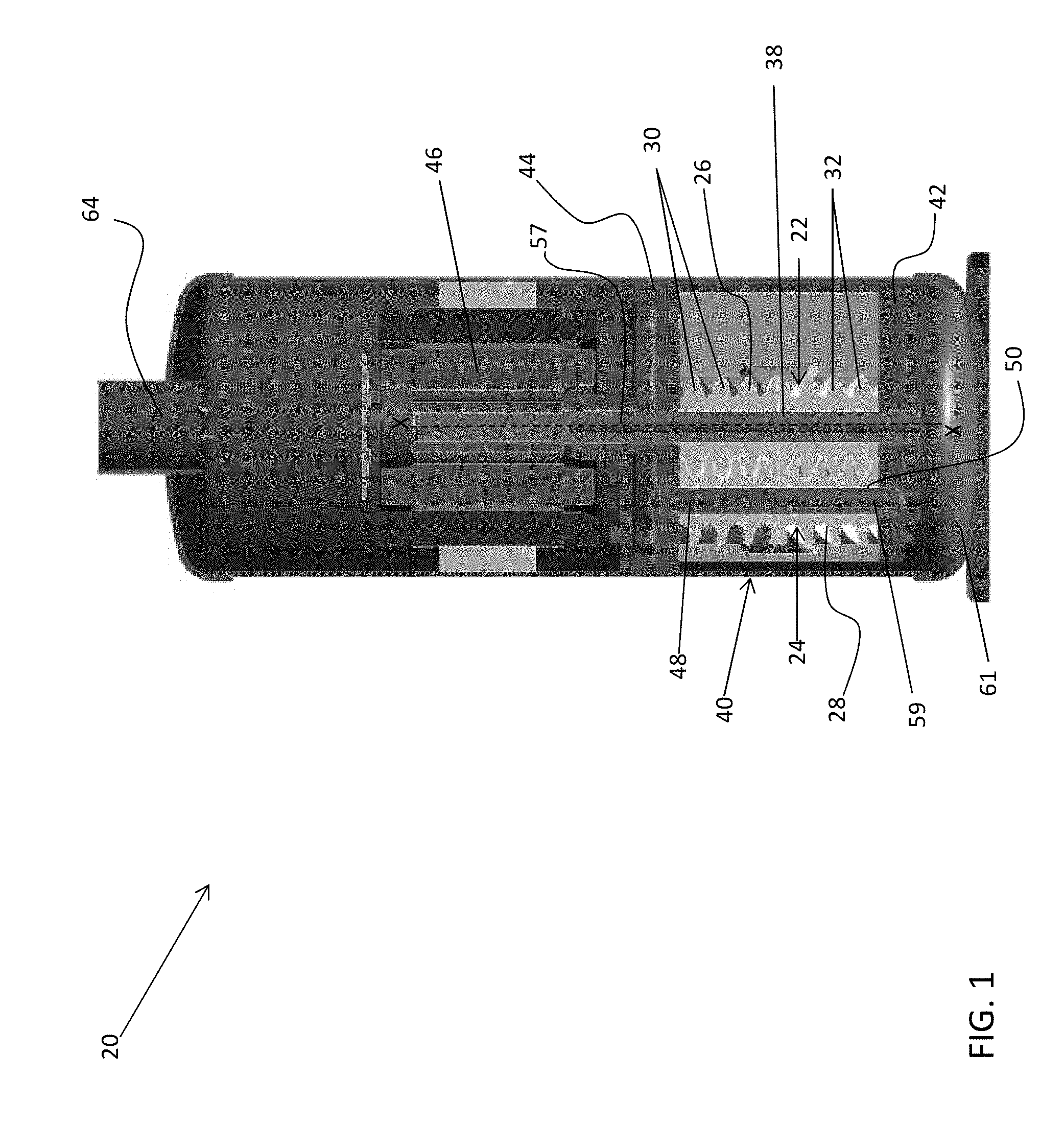
[0026] FIG. 1 is cross-sectional view of a fluid machine according to an embodiment;
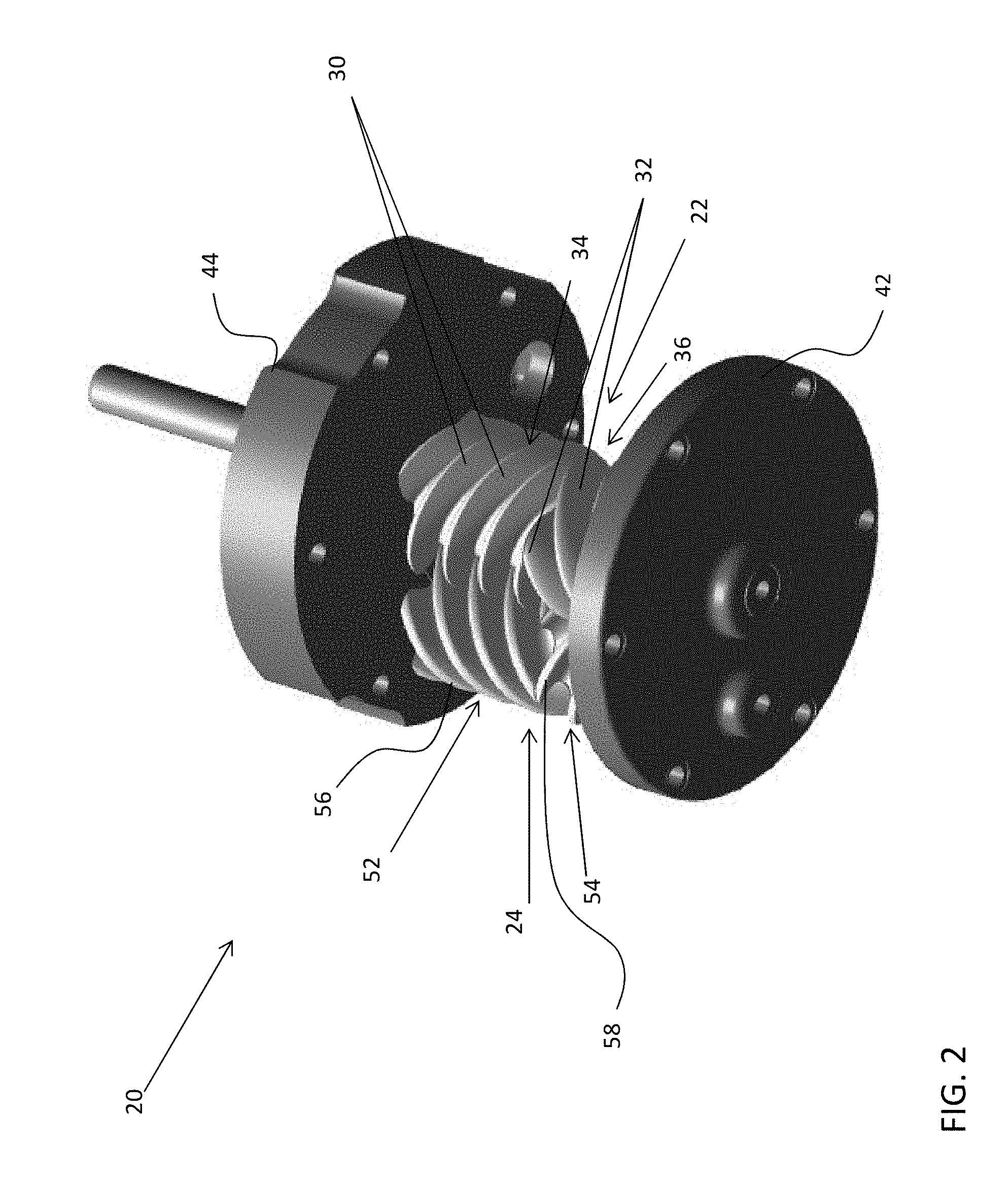
[0027] FIG. 2 is a perspective view of a fluid machine according to an embodiment;
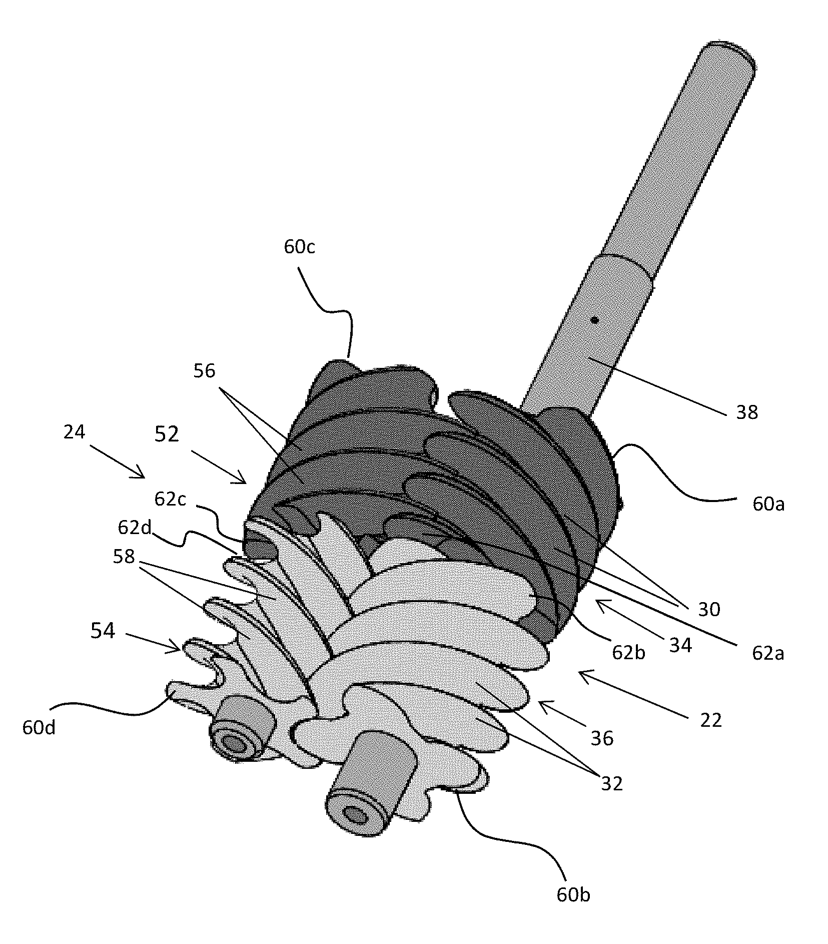
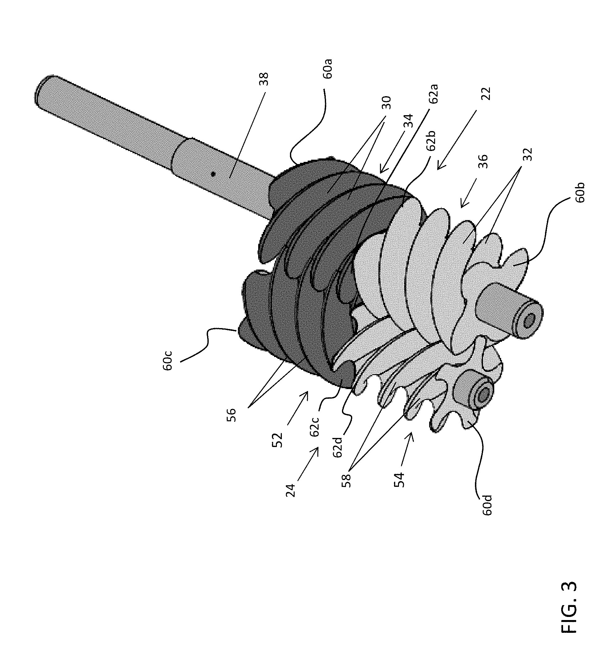
[0028] FIG. 3 is a perspective view of the first rotor and the second rotor according to an embodiment;
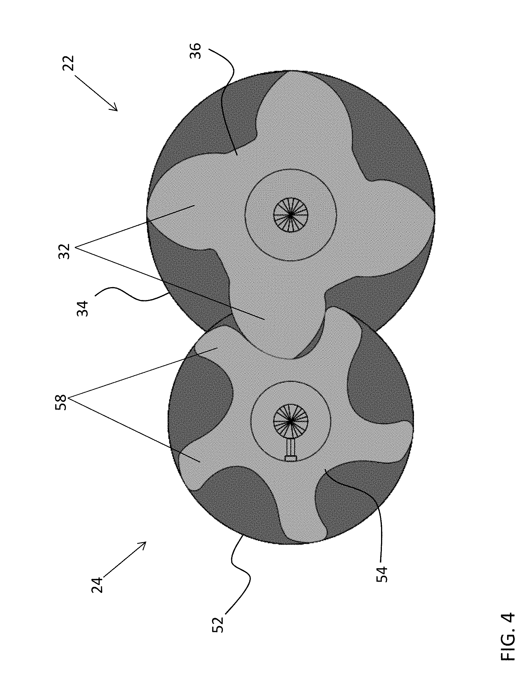
[0029] FIG. 4 is an end view of the first rotor and the second rotor of FIG. 3 according to an embodiment;
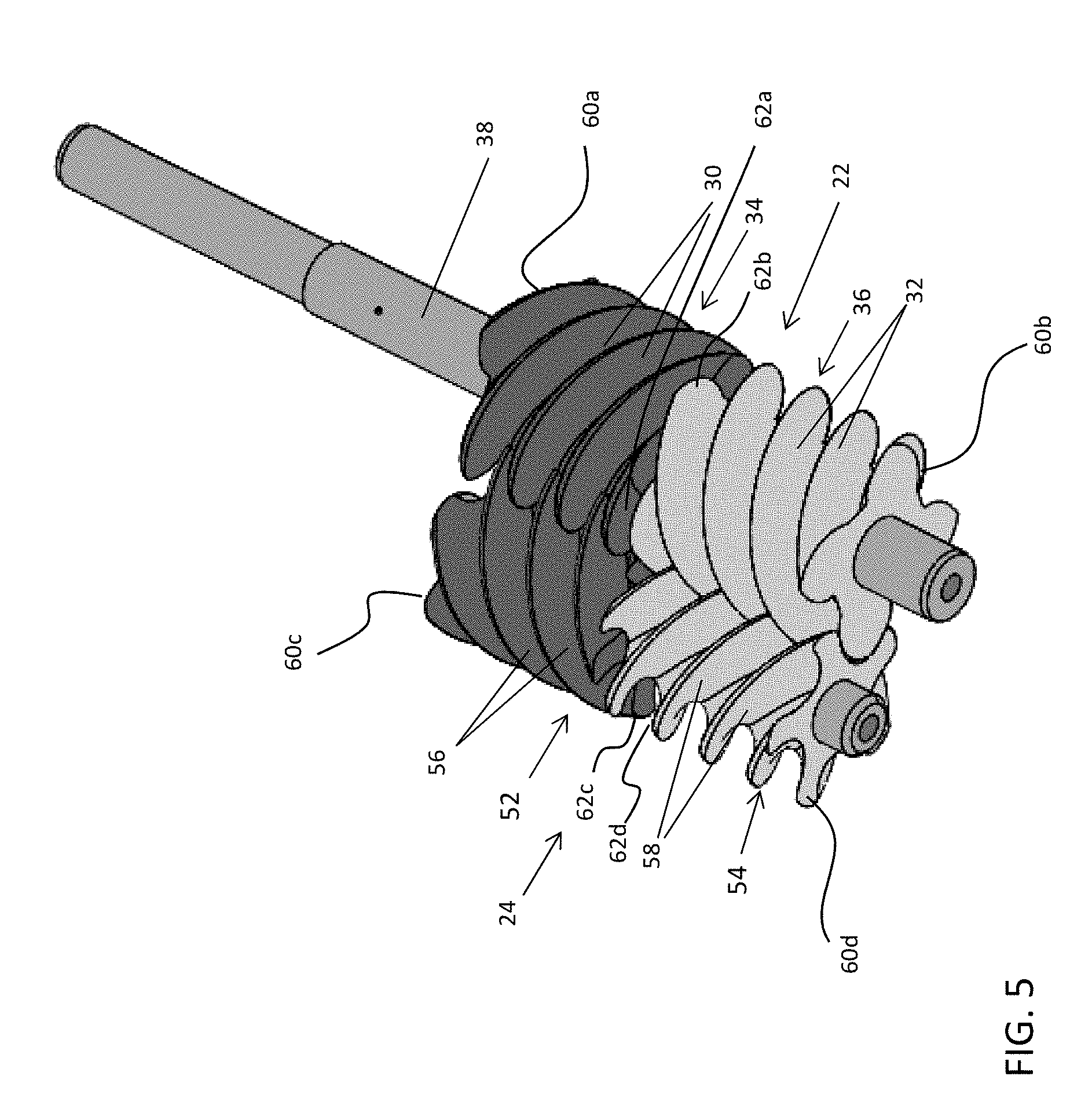
[0030] FIG. 5 is a perspective view of the first rotor and the second rotor according to an embodiment; and
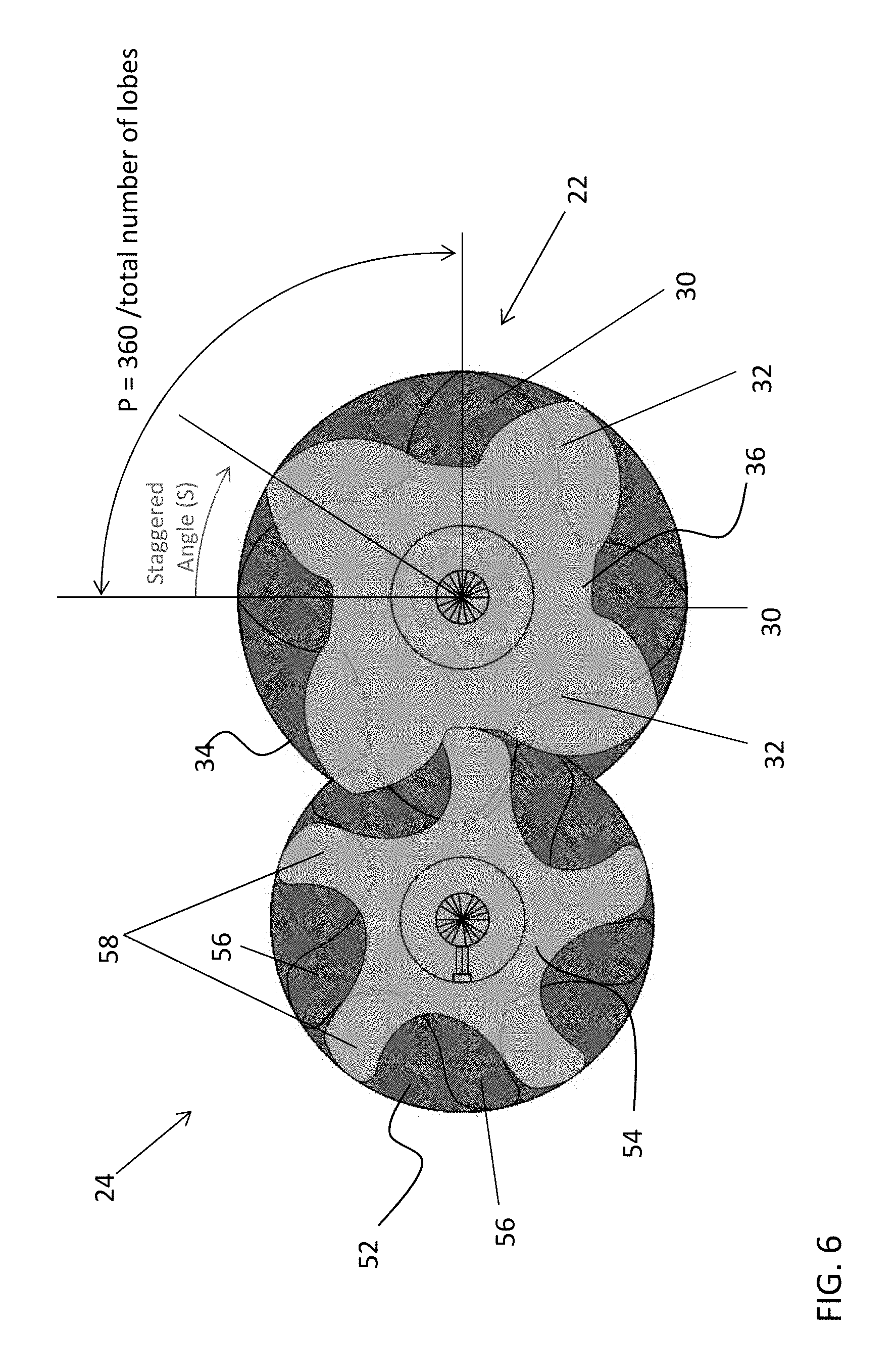
[0031] FIG. 6 is an end view of the first rotor and the second rotor of FIG. 5 according to an embodiment.
[0032] The detailed description explains embodiments of the disclosure, together with advantages and features, by way of example with reference to the drawings.
DETAILED DESCRIPTION
[0033] Referring now to the FIGS. 1 and 2, a fluid machine 20 is illustrated. In the illustrated, non-limiting embodiment, the fluid machine 20 is an opposed screw compressor. However, other suitable embodiments of a fluid machine, such as a pump, fluid motor, or engine for example, are also within the scope of the disclosure. The fluid machine 20 includes a first rotor 22 intermeshed with a second rotor 24. In an embodiment, the first rotor 22 is a male rotor having a male-lobed working portion 26 and the second rotor 24 is a female rotor including a female-lobed portion 28. Alternatively, the first rotor 22 may be a female rotor and the second rotor 24 may be a male rotor. The working portion 26 of the first rotor 22 includes at least one first helical lobe 30 and at least one second helical lobe 32. In the illustrated, non-limiting embodiment, the first rotor 22 includes two separate portions 34, 36 defining the first helical lobes 30 and the second helical lobes 32, respectively.
[0034] The fluid machine 20 includes a first shaft 38 fixed for rotation with the first rotor 22. The fluid machine 20 further include a casing 40 rotatably supporting the first shaft 38 and at least partially enclosing the first rotor 22 and the second rotor 24. A first end 42 and a second end 44 of the casing 40 are configured to rotatably support the first shaft 38. The first shaft 38 of the illustrated embodiments is directly coupled to an electric motor 46 operable to drive rotation of the first shaft 38 about an axis X. Any suitable type of electric motor 46 is contemplated herein, including but not limited to an induction motor, permanent magnet (PM) motor, and switch reluctance motor for example. In an embodiment, the first rotor 22 is fixed to the first shaft 38 by a fastener, coupling, integral formation, interference fit, and/or any additional structures or methods known to a person having ordinary skill in the art (not shown), such that the first rotor 22 and the first shaft 38 rotate about axis X in unison.
[0035] The fluid machine 20 additionally includes a second shaft 48 operable to rotationally support the second rotor 24. The second rotor 24 includes an axially extending bore 50 within which the second shaft 48 is received. In an embodiment, the second shaft 48 is stationary or fixed relative to the casing 40 and the second rotor 24 is configured to rotate about the second shaft 48. However, embodiments where the second shaft 48 is also rotatable relative to the casing 40 are also contemplated herein.
[0036] With specific reference to FIG. 2, the first rotor 22 is shown as including a first portion 34 having four first helical lobes 30 and a second portion 36 having four second helical lobes 32. The illustrated, non-limiting embodiment, is intended as an example only, and it should be understood by a person of ordinary skill in the art that any suitable number of first helical lobes 30 and second helical lobes 32 are within the scope of the disclosure. As shown, the first helical lobes 30 and the second helical lobes 32 have opposite helical configurations. In the illustrated, non-limited embodiment, the first helical lobes 30 are left-handed and the second helical lobes 32 are right-handed. Alternatively, the first helical lobes 30 may be right-handed and the second helical lobes 32 may be left-handed.
[0037] By including lobes 30, 32 with having opposite helical configurations, opposing axial flows are created between the first and second helical lobes 30, 32. Due to the symmetry of the axial flows, thrust forces resulting from the helical lobes 30, 32 are generally equal and opposite, such that the thrust forces substantially cancel one another. As a result, this configuration of the opposing helical lobes 30, 32 provides a design advantage since the need for thrust bearings in the fluid machine can be reduced or eliminated.
[0038] The second rotor 24 has a first portion 52 configured to mesh with the first helical lobes 30 and a second portion 54 configured to mesh with the second helical lobes 32. To achieve proper intermeshing engagement between the first rotor 22 and the second rotor 24, each portion 52, 54 of the second rotor 24 includes one or more lobes having an opposite configuration to the corresponding helical lobes 30, 32 of the first rotor 22. In the illustrated, non-limiting embodiment, the first portion 52 of the second rotor 24 has at least one right-handed lobe 56, and the second portion 54 of the second rotor 24 includes at least one left-handed lobe 58.
[0039] In an embodiment, the first portion 52 of the second rotor 24 is configured to rotate independently from the second portion 54 of the second rotor 24. However, embodiments where the first and second portions 52, 54 are rotationally coupled are also contemplated herein. Each portion 52, 54 of the second rotor 24 may include any number of lobes 56, 58. In an embodiment, the total number of lobes 56, 58 formed in each portion 52, 54 of the second rotor 24 is generally larger than a corresponding portion, 34 and 36, respectively, of the first rotor 22. For example, if the first rotor 22 includes four first helical lobes 30, the first portion 54 of the second rotor 24 configured to intermesh with the first helical lobes 30 may include five helical lobes 56. However, embodiments where the total number of lobes 56, 58 in a portion 52, 54 of the second rotor 24 is equal to a corresponding group of helical lobes (i.e. the first helical lobes 30 or the second helical lobes 32) of the first rotor 22 are also within the scope of the disclosure.
[0040] Returning to FIG. 1, the fluid machine 20 may include a first shaft passage 57 extending axially through the first shaft 38 and a second shaft passage 59 extending axially through a portion of the second shaft 48. The first shaft passage 57 and/or the second shaft passage 59 communicate lubricant from a sump 61, through first shaft 38 and/or second shaft 48, out one or more radial passages (not shown), and along one or more surfaces of the first rotor 22 and/or the second rotor 24. The fluid machine 20 further includes an axially-extending passage (not shown) defined between the second shaft 48 and the bore 50 formed in the second rotor 24. The passage is configured to allow lubricant to pass or circulate there through. In an embodiment, relatively high pressure discharge at first and second ends 42, 44 of the casing 40, the first rotor 22, and the second rotor 24 and relatively low pressure suction at a central location of the first rotor 22 and the second rotor 24 urge lubricant through each of the passages. The circulation of lubricant through the passage disposed between bore 50 and the second shaft 48 provides internal bearing surfaces between each of the first and second portions 52, 54 and the second shaft 48 to reduce friction there between and further allow the first portion 52 of the second rotor 24 to rotate independently of the second portion 54 of the second rotor 24.
[0041] During operation of the fluid machine 20 of one embodiment, a gas or other fluid, such as a low GWP refrigerant for example, is drawn to a central location by a suction process generated by the fluid machine 20. Rotation of the first rotor 22 and the second rotor 24 compresses the refrigerant and forces the refrigerant toward first and second ends 42, 44 of the casing 40 between the sealed surfaces of the meshed rotors 22, 24 due to the structure and function of the opposing helical rotors 22, 24. The compressed refrigerant is routed by an internal gas passage within the casing 40 and discharged through the second end 44 of the casing 40. The discharged refrigerant passes through the electric motor 46 and out of a discharge passage 64.
[0042] With reference now to FIGS. 3-6, the first rotor 22 and the second rotor 24 are illustrated in more detail. Each portion 34, 36 of the first rotor 22, and each portion 52, 54 of the second rotor 24 has a first end 60 (shown as 60a-60d), for example arranged adjacent a surface of the casing 40, and a second end 62, facing a corresponding portion of the rotor 22, 24. In an embodiment, the second end of each portion 34, 36, 52, 54 has a generally planar surface, such as extending substantially perpendicular to the rotational axis of the corresponding rotor 22, 24 for example. As a result, the second end of a portion 34, 36, 52, 54 includes a cross-section of each of the plurality of lobes included in that portion 34, 36, 52, 54. The cross-section of each lobe 30, 32, 56, 58 defines a lobe shape. The lobe shapes for each of the plurality of lobes 30, 32, 56, 58 within a portion 34, 36, 52, 54 may be substantially identical, as shown in the illustrated, non-limiting embodiment, or alternatively, may vary.
[0043] The lobe shapes defined at the second end 62a of the first portion 34 of the first rotor 22 may be substantially identical to the lobe shapes defined at an adjacent second end 62b of the second portion 36 of the first rotor 22. Alternatively, or in addition, the lobe shapes defined at a second end 62c of the first portion 52 of the second rotor 24 may be substantially identical to the lobe shapes defined at an adjacent second end 62d of the second portion 54 of the second rotor 24. With specific reference now to FIGS. 3 and 4, in an embodiment, the first portion 34 and the second portion 36 of the first rotor 22 are arranged such that the ends of the lobes 30 at the second end 62a of the first portion 34 are substantially aligned with the ends of the lobes 32 at the second end 62b of the second portion 36. Accordingly, each of the lobe shapes of the second portion 36 is substantially aligned with a corresponding lobe shape of the first portion 34. Because the lobe shapes of the first portion 34 and the second portion 36 are identical in the embodiment of FIG. 4, only the lobe shapes of the second portion 36 are visible.
[0044] In embodiments where the lobes at the second ends 62 of the first portion 34 and the second portion 36 of a rotor, such as the first rotor 22 for example, are substantially aligned, the lobes at the second ends 62 of the first and second portion 52, 54 of the other rotor, for example the second rotor 24, may, but need not be aligned. As shown in FIGS. 3 and 4, the lobe ends of the first and second portion 52, 54 are arranged such that the lobe shapes formed at the first end 62c of the first portion 52 of the second rotor 24 are substantially aligned with the lobe shapes formed at the adjacent second end 62d of the second portion 54 of the second rotor 24. By aligning the lobes of the first portion 34, 52 and second portion 36, 54 of one or more of the rotors 22, 24 (i.e. an "aligned" configuration), an axial force balance may be achieved thereby minimizing or eliminating chattering of the rotors 22, 24. Embodiments where at least one of the rotors 22, 24 has an aligned configuration may be particularly beneficial in a fluid machine 20 having a small tonnage.
[0045] In another embodiment, the first portion 34, 52 and the second portion 36, 54 of at least one of the first rotor 22 and the second rotor 24, respectively, are arranged in a staggered configuration. With reference now to FIGS. 5 and 6, in a staggered configuration, the first portion 34 and the second portion 36 of the first rotor 22 are arranged such that the ends of the lobes 30 at the second end 62a of the first portion 34 are rotated relative to the ends of the lobes 32 at the second end 62b of the second portion 36. Accordingly, each of the lobe shapes of the second portion 36 is rotated relative to a corresponding lobe shape of the first portion 34. Similarly, the lobe ends of the first and second portion 52, 54 may be arranged such that the lobe shapes formed at the first end 62c of the first portion 52 of the second rotor 24 are rotated relative to the lobe shapes formed at the adjacent second end 62d of the second portion 54 of the second rotor 24. Although both the first rotor 22 and the second rotor 24 are illustrated as having a staggered configuration, embodiments where only one of the first and second rotor 22, 24 has a staggered configuration are also contemplated herein.
[0046] In the staggered configuration, the lobes at the end 62b, 62d of the second portion 36, 54, are arranged at an angle relative to the lobes at the end 62a, 62c of the first portion 34, 52 of a rotor 22, 24. As shown, the angle of the stagger S is measured between a radius of a lobe 30, 56 of the first portion 34, 52 and a radius of an adjacent lobe 32, 58 of the corresponding second portion 36, 54. The degree of the angle of stagger S must be greater than zero and less than the angular pitch, P, of lobes 30, 56 at the end 62a, 62c of the first portion 34, 52. The angular pitch P of the lobes 30, 56 on the first portion 34, 52 of a rotor 22, 24 is calculated by dividing 360.degree. by the total number of lobes 30, 56 of the portion 34, 52. For example, in the non-limiting embodiment of FIG. 6, the angular pitch P of the first portion 34 of the first rotor 22 is 90.degree.. Accordingly, the stagger angle S is greater than 0.degree. and less than 90.degree.. In an embodiment, the staggered angle S is between about 10% and about 90% of the angular pitch, and more specifically between about 25% and about 75% of the angular pitch P. However, any suitable staggered angle S is contemplated herein. This is distinguishable from the aligned configuration where the angle of stagger S is equal to zero, or in some embodiments, the angle of stagger S is within 5% of the angular pitch P. By configuring at least one of the rotors 22, 24 in a staggered configuration, the gas pulsation level, and the corresponding noise level associated therewith, may be reduced. Embodiments where at least one of the rotors 22, 24 has a staggered configuration may be particularly beneficial in a fluid machine 20 having a large tonnage.
[0047] While the disclosure has been described in detail in connection with only a limited number of embodiments, it should be readily understood that the disclosure is not limited to such disclosed embodiments. Rather, the disclosure can be modified to incorporate any number of variations, alterations, substitutions or equivalent arrangements not heretofore described, but which are commensurate with the spirit and scope of the disclosure. Additionally, while various embodiments of the disclosure have been described, it is to be understood that aspects of the disclosure may include only some of the described embodiments. Accordingly, the disclosure is not to be seen as limited by the foregoing description, but is only limited by the scope of the appended claims.
* * * * *
D00000
D00001
D00002
D00003
D00004
D00005
D00006
XML
uspto.report is an independent third-party trademark research tool that is not affiliated, endorsed, or sponsored by the United States Patent and Trademark Office (USPTO) or any other governmental organization. The information provided by uspto.report is based on publicly available data at the time of writing and is intended for informational purposes only.
While we strive to provide accurate and up-to-date information, we do not guarantee the accuracy, completeness, reliability, or suitability of the information displayed on this site. The use of this site is at your own risk. Any reliance you place on such information is therefore strictly at your own risk.
All official trademark data, including owner information, should be verified by visiting the official USPTO website at www.uspto.gov. This site is not intended to replace professional legal advice and should not be used as a substitute for consulting with a legal professional who is knowledgeable about trademark law.