Apparatus And Method For Pumping Fluid In A Borehole
ROSS; Shaun Compton ; et al.
U.S. patent application number 16/302649 was filed with the patent office on 2019-05-02 for apparatus and method for pumping fluid in a borehole. The applicant listed for this patent is METROL TECHNOLOGY LIMITED. Invention is credited to Leslie David JARVIS, Shaun Compton ROSS.
| Application Number | 20190128080 16/302649 |
| Document ID | / |
| Family ID | 56410582 |
| Filed Date | 2019-05-02 |


| United States Patent Application | 20190128080 |
| Kind Code | A1 |
| ROSS; Shaun Compton ; et al. | May 2, 2019 |
APPARATUS AND METHOD FOR PUMPING FLUID IN A BOREHOLE
Abstract
A method to manipulate a well, comprising running an apparatus having a container and an electrically powered pump into the well. The well is isolated, and a wireless control signal, such as an electromagnetic or acoustic signal, is sent to operate the pump in response in order to pump fluid from within the container to the surrounding portion of the well. The apparatus may comprise a pressure balancing means, such as a floating piston between two ports of the container, and/or an in well charging means.
| Inventors: | ROSS; Shaun Compton; (Aberdeen, Aberdeenshire, GB) ; JARVIS; Leslie David; (Stonehaven, Aberdeenshire, GB) | ||||||||||
| Applicant: |
|
||||||||||
|---|---|---|---|---|---|---|---|---|---|---|---|
| Family ID: | 56410582 | ||||||||||
| Appl. No.: | 16/302649 | ||||||||||
| Filed: | May 26, 2017 | ||||||||||
| PCT Filed: | May 26, 2017 | ||||||||||
| PCT NO: | PCT/GB2017/051517 | ||||||||||
| 371 Date: | November 18, 2018 |
| Current U.S. Class: | 1/1 |
| Current CPC Class: | E21B 47/06 20130101; E21B 49/00 20130101; E21B 33/12 20130101; E21B 47/07 20200501; E21B 49/081 20130101; E21B 43/26 20130101; E21B 27/02 20130101; E21B 43/04 20130101; E21B 43/11 20130101; E21B 34/06 20130101 |
| International Class: | E21B 27/02 20060101 E21B027/02; E21B 47/06 20060101 E21B047/06; E21B 49/00 20060101 E21B049/00; E21B 33/12 20060101 E21B033/12; E21B 49/08 20060101 E21B049/08 |
Foreign Application Data
| Date | Code | Application Number |
|---|---|---|
| May 26, 2016 | GB | 1609286.8 |
Claims
1. A method to manipulate a well, comprising: providing an apparatus in the well below an annular sealing device the annular sealing device engageing with one of an inner face of casing and a wellbore in the well, and being at least 100 m below a surface of the well; and wherein a connector is provided connecting the apparatus to the annular sealing device, the connector being above the apparatus and below the annular sealing device; the apparatus comprising: a container having a volume of at least 1 litre (l); a port to allow fluid communication between a portion of the container and a surrounding portion of the well; an electrically powered pump configured to direct fluids to/from the container from/to the surrounding portion of the well; a battery to supply electrical power to the pump; a control mechanism to control the pump, and comprising a communication device configured to receive a control signal for operating the pump; running the apparatus into the well; then, isolating the port of the apparatus from a surface of the well; sending a control signal to the communication device at least in part by a wireless control signal transmitted in at least one of the following forms: electromagnetic and acoustic; operating the pump in response to said control signal and pumping fluid from within the container to the surrounding portion of the well; and wherein at least one pressure sensor is provided in the well below the annular sealing device, the at least one pressure sensor coupled to a wireless transmitter; and wherein data is transmitted from the transmitter to above the annular sealing device.
2. A method as claimed in claim 1, wherein the apparatus is connected to a tubular before the pump is operated.
3. (canceled)
4. A method as claimed in claim 1, wherein the electrical pump is a positive displacement pump, optionally a reciprocating piston pump which is reciprocated at least five times.
5. A method as claimed in claim 1, wherein the fluid pumped into the surrounding portion of the well includes at least 1 l of fluid added to the apparatus before it was run into the well.
6. A method as claimed in claim 1, wherein the fluid is one of an acid, breaker fluid, tracer, gelling chemical and inhibitor.
7. A method as claimed in claim 1, including using the apparatus to conduct at least one of an interval injectivity test, permeability test, pressure test, hydraulic fracturing test, a barrier test, a chemical delivery operation, and well/reservoir treatment such as an acid treatment.
8. A method as claimed in claim 7, wherein the apparatus is used to conduct a pressure test, the pressure test being conducted on a barrier by the apparatus being provided below the barrier, the pump being operated causing fluid to be released from the container to increase pressure below the barrier, and the pressure below the barrier is then monitored.
9. A method as claimed in claim 8, further comprising a charging system having a valve on at least one of the and another port, the method including providing gas in the container, exposing the gas to well pressure via said port to compress the gas, closing said port with said valve to resist fluid and pressure communication from the well into the container, using the compressed gas to facilitate the pump to release fluid from the container into the well, and; wherein optionally before the barrier is set, the well is pressurised from surface to further increase the pressure in the well and further compress the gas in the container, the valve at the port being closed before the pressure from the surface is reduced.
10.-13. (canceled)
14. A method as claimed in claim 1, wherein the container has at least one of a floating piston and bladder separating a first and a second section in the container and sealing them from each other within the container, the first section being in fluid communication with the port.
15.-28. (canceled)
29. A method as claimed in claim 1, wherein the port of the apparatus is provided above a second annular sealing device.
30. A method as claimed in claim 29, including conducting a short interval test wherein the packer element of the annular sealing device and a packer element of the second annular sealing device are less than 30 m apart, or less than 10 m apart, optionally less than 5 m apart, more optionally less than 2 m, less than lm or less than 0.5 m; and there is at least one communication path from the well to the reservoir between the packer elements.
31. (canceled)
32. A method as claimed in claim 1, wherein the apparatus is deployed into the well in the same operation as deploying the annular sealing device into the well.
33. A method as claimed in claim 32, wherein the apparatus is conveyed on one of tubing, drill pipe and casing/liner.
34.-36. (canceled)
37. A method as claimed in claim 1 further comprising conducting a procedure on the well, wherein the procedure includes at least one of a build-up test, drawdown test, connectivity tests such as one of, an interference test and pulse test, drill stem test (DST), extended well test (EWT), hydraulic fracturing, minifrac, pressure test, flow test, well/reservoir treatment such as an acid treatment, permeability test, injection procedure, gravel pack operation, perforation operation, image capture, string deployment, workover, suspension and abandonment.
38. A method as claimed in any claim 1, wherein the well comprises an array of discrete temperature sensors or a distributed temperature sensor.
39. A method as claimed in claim 1, wherein the container has a volume of at least 5 l at least 50 l, optionally at least 100 l.
40. (canceled)
41. A method as claimed in claim 1, wherein the well includes casing/liner, and the container takes up the whole cross-section of the casing/liner.
42. (canceled)
43. A method as claimed in claim 1, wherein in addition to the container, there is at least one secondary container having a volume of at least 1 l, the at least one secondary container having a control device for controlling communication between the secondary container and the surrounding portion of one of the well and other portion of the apparatus, wherein the control device includes at least one of a mechanical valve and a latch assembly, and wherein at least one secondary container has a different pressure than a surrounding portion of the well.
44.-55. (canceled)
56. A method to manipulate a well by conducting a short interval test, comprising: providing a pressure sensor in the well; providing an apparatus in the well, the apparatus comprising a container having a volume of at least 5 litres and a port to allow fluid and optionally pressure communication between a portion of an inside of the container and an outside of the container; the port of the apparatus being below a first portion of a packer element and above a second portion of a or the packer element, said portions spaced apart from each other by up to 10 m thus defining a short interval, and each engaging with an inner face of casing or wellbore in the well, and being at least 100 m below a surface of the well; the short interval including at least one communication path between the well and the formation; the apparatus further comprising: a pump adapted to move fluid from the surrounding portion of the well into at least a portion of the container via the port; a control mechanism comprising a communication device configured to receive a control signal for moving the valve member; deploying the apparatus into the well on a tubular, sending a control signal from outwith the short interval to the control mechanism at least in part by a wireless control signal transmitted in at least one of the following forms: electromagnetic, acoustic, inductively coupled tubulars and coded pressure pulsing; operating the pump in response to said control signal to allow fluid to enter the container; and, drawing in at least 5 litres of fluid into the container from the well.
Description
[0001] This invention relates to an apparatus and method for pumping fluid in a borehole or well.
[0002] Boreholes are commonly drilled for a variety of reasons in the oil and gas industry, not least to function as wells to recover hydrocarbons, but also as test wells, observation wells or injection wells.
[0003] On occasion, it may be necessary to deploy fluid into the well. For example, an acid treatment may be conducted where a chemical, often hydrochloric acid based, is deployed in a well in order to remove or mitigate blockages or potential blockages, such as scale, in the well. This can also be used to treat perforations in the well.
[0004] In order to deploy the acid treatment, fluid may be pumped from surface through the tubing. However this may not accurately direct the fluid to the specific area of the well or formation required.
[0005] In order to more accurately deploy fluid into a required area of the well, coiled tubing may be used. A 2'' diameter coiled tube, for example, can be deployed into the well. The acid treatment is then pumped down the tube and exits into the well at the appropriate area.
[0006] Whilst generally satisfactory, the inventors of the present invention have noted that deploying fluids in such a manner can be capital intensive requiring considerable rig time and large volumes of fluid. When using coiled tubing, many thousands of feet is often required (depending on the well depth). Moreover it is a time-consuming process to launch the coiled tubing, deploy the fluid, and then recover the coiled tubing. Sometimes coiled tubing cannot access parts of the well due to the configuration of the bottom hole assembly, and may not be able to deploy the fluid to the particular area intended.
[0007] A number of other fluids may be deployed in a well, such as a tracer or breaker fluid.
[0008] Hydraulic fracturing or various pressure tests, such as an interval injectivity test and a permeability test, can also be carried out using pressure applied from surface. However certain portions of the well may be isolated from the surface, or it may not be possible to isolate certain portions of the well from other portions, whilst maintaining pressure connection to the surface.
[0009] The inventors of the present invention have sought to mitigate one or more of the problems of the prior art.
[0010] According to a first aspect of the present invention, there is provided a method to manipulate a well, comprising: [0011] providing an apparatus, the apparatus comprising: [0012] a container having a volume of at least 1 litre; [0013] a port to allow fluid communication between a portion of the container and the surrounding portion of the well; [0014] an electrically powered pump configured to direct fluids to/from the container from/to the surrounding portion of the well; [0015] a battery to supply electrical power to the pump; [0016] a control mechanism to control the pump comprising a communication device configured to receive a control signal for operating the pump; [0017] running the apparatus into the well; [0018] optionally isolating the port of the apparatus from a surface of the well; [0019] sending a control signal to the communication device at least in part by a wireless control signal transmitted in at least one of the following forms: electromagnetic, acoustic, inductively coupled tubulars and coded pressure pulsing; [0020] operating the pump in response to said control signal and optionally pumping fluid from within the container to the surrounding portion of the well.
[0021] As described in more detail below, the apparatus may include a wireless communication device and/or a floating piston within the container (for example to pressure balance or for charging).
[0022] Thus, according to a second aspect, the present invention also provides an apparatus comprising: [0023] a container having a volume of at least 1 litre; [0024] a port to allow fluid communication between a portion of the container and the surrounding portion of the well; [0025] an electrically powered pump configured to direct fluids to/from the container from/to the surrounding portion of the well; [0026] a battery to supply electrical power to the pump; [0027] a control mechanism to control the pump comprising a communication device configured to receive a control signal for operating the pump, said communication device being a wireless communication device; and, [0028] a floating piston or bladder in the container.
[0029] The pump may be provided at the port.
[0030] Often, the pump is operated to pump fluid from within the container to the surrounding portion of the well. Often this is at least one litre or more than five litres of fluid which has been added to the container at the surface before the apparatus is run into the well. This fluid may be used to treat the well/reservoir.
[0031] The electrical pump is preferably a positive displacement pump such as a piston pump, gear type pump, screw pump, diaphragm, lobe pump; especially a piston or gear pump. Alternatively the pump may be a velocity pump such as a centrifugal pump.
[0032] The pump may be operable to pump fluids at a rate of 0.01 cc/s to 20 cc/s.
[0033] The pump operation or rate can be controlled in response to a further control signal being received by the wireless communication device (or this may be an instruction in the original signal).
[0034] The step of sending a control signal to the communication device is normally after the step of isolating the port of the apparatus from the well but for certain embodiments, it may be before.
[0035] The entire apparatus, and not just the port of the apparatus, may be isolated from the surface of the well.
[0036] Isolating the port of the apparatus from the surface of the well means preventing pressure or fluid communication between the port and the surface of the well.
[0037] Isolation can be achieved using the well infrastructure and isolating components. Isolating components comprise packers, plugs such as bridge plugs, valves, and/or the apparatus. In contrast, well infrastructure comprises cement in an annulus, casing and/or other tubulars. In certain embodiments, more than one isolating component can isolate the port of the apparatus from the surface of the well. For example, a packer may be provided in an annulus and a valve provided in a central tubing and together they isolate the port of the apparatus from the surface of the well. In such cases the uppermost extent of the well section that contains the port of the apparatus is defined by the uppermost isolating component.
[0038] Isolating the port of the apparatus from the surface of the well involves isolating the section of the well containing the port downhole, such that the uppermost isolating component in that isolated well section is at least 100 m from the surface of the well, optionally at least 250 m, or at least 500 m.
[0039] The port of the apparatus is typically at least 100 m from the uppermost isolating component in the same section of the well. In certain embodiments, the port of the apparatus is at most 500 m from the uppermost isolating component in the same section of the well, optionally at most 200 m therefrom.
[0040] The well or a section thereof may be shut in, at surface or downhole, after the apparatus has been run and before operating the pump.
[0041] The step of isolating the port of the apparatus from the surface of the well may include shutting in at least a section of the well. For example the well can be shut in above the port of the apparatus, which isolates the port of the apparatus from the surface of the well.
[0042] For other embodiments at least a section of the well can be shut in separate to this isolating step, for example, below the apparatus, or the well may have been shut in at an earlier date.
[0043] Isolating the port of the apparatus from the surface of the well, and optionally shutting in the well, can reduce the volume exposed to the apparatus which then focuses the released fluid to the intended area.
[0044] The isolating components may be upper isolating components, and lower isolating components may be used to isolate a section of the well from a further section therebelow.
[0045] Thus embodiments of the present invention allow the release of fluids in a lower isolated section of a well where it may not have hitherto been possible, convenient or indeed safe to do so using conventional means such as fluid control lines to surface.
[0046] The well may be a production well.
Pressure Balancing Means
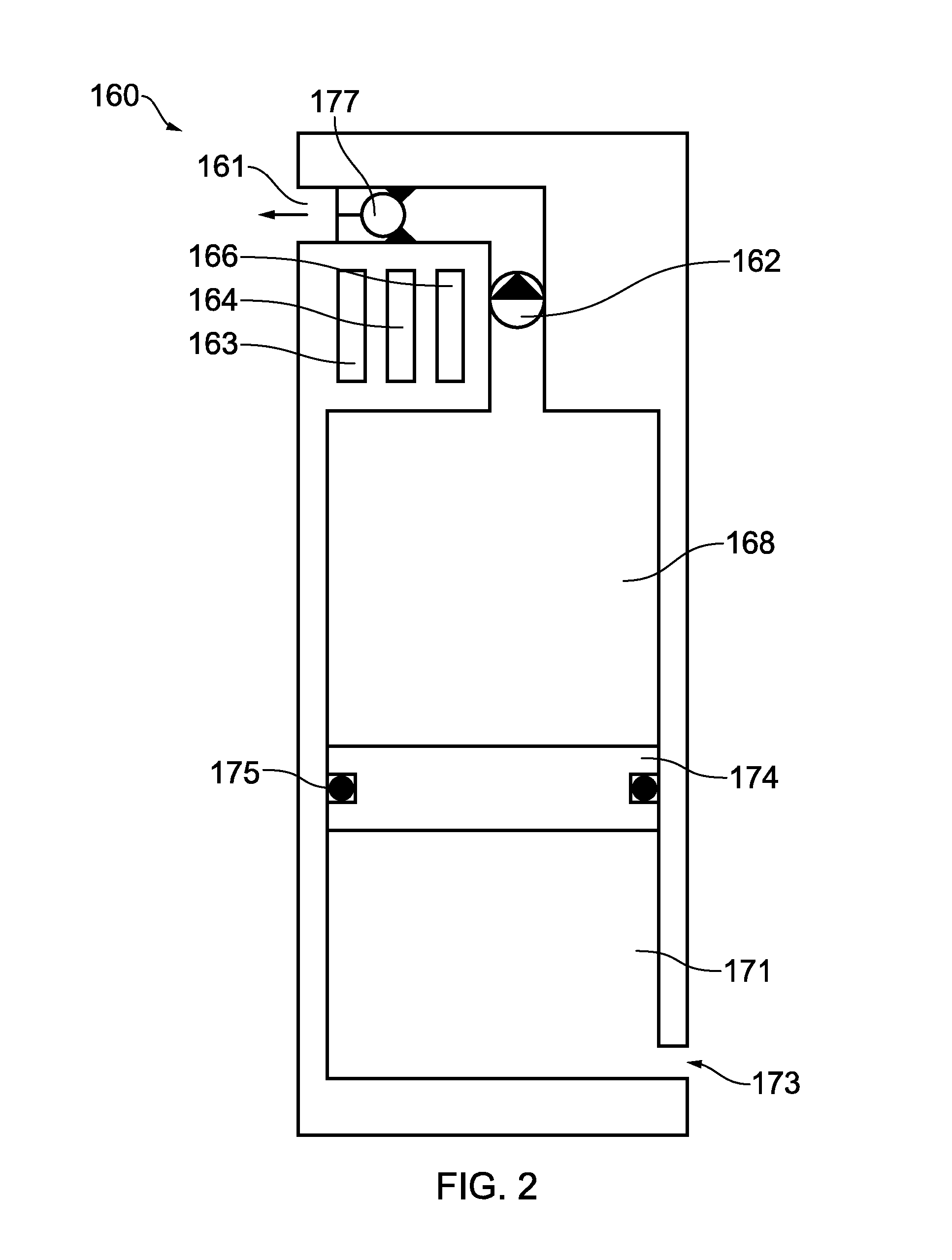
[0047] The apparatus may comprise a pressure balancing means. The port may be a first port, and a second port may be provided in the apparatus between the container and a surrounding portion of the well, the first and second ports separated within the apparatus by a pressure balancing device such as a bladder or a floating piston.
[0048] In a first embodiment with a pressure balancing means, the pump is normally provided at one of the ports (preferably the first port), the fluid being pumped to/from the container is provided between the floating piston and said first port. An opposite side of the floating piston is exposed to well pressure via the second port, thus balancing the pressure on both sides of the floating piston.
[0049] In a second embodiment with a pressure balancing means, the pump is provided between said floating piston and the first port and a second floating piston is provided between the pump and the first port. The pump is thus between the two floating pistons. The first floating piston functions as a pressure balancing means and the second floating piston controls fluid ingress/egress from the container through the first port. A control fluid is provided in the container, between the respective floating pistons, and this control fluid can be pumped by the pump, which in turn causes the second floating piston to move and direct fluid to be expelled or drawn into the container, between the first port and the second floating piston.
[0050] The second embodiment is particularly suited for apparatus where fluid can be both expelled and drawn in (in either order) since the pump is operating on a controlled fluid.
[0051] For embodiments with pressure balancing means, the pump can then direct fluids in or out of the container with less or with no requirement to overcome a pressure differential between the container and the surrounding portion of the well.
[0052] Pressure balancing means is not essential. Embodiments used for barrier testing from below a barrier may especially be used without one. Nevertheless, in such a case, it is preferred to have a small (variable) amount of gas at, for example, more than 100 psi, within the container to stop the pump acting against a vacuum. Indeed, a higher pressure, such as over 1000 psi also helps the pump operate.
[0053] In any case, the pump can pump the fluid directly i.e. the fluid moving to/from the surrounding portion of the well to the container; or indirectly for example the control fluid which acts on the fluid moving to/from the surrounding portion of the well indirectly, for example via a floating piston, to the container.
Pump Options
[0054] The electrical pump may drive another pump which in turn moves the fluid to/from the container from/to the surrounding portion of the well. This second pump need not be electrical; rather the `prime mover` is electrical.
[0055] The pump may comprise a piston with a motorised lead screw option, akin to a syringe.
[0056] A single stroke of such a piston or lead screw may be sufficient in certain applications, although for other applications the piston is reciprocated.
[0057] This single stroke option is particularly suited to smaller volume applications (for example up to 5 litres) and also where either side of the piston is pressure balanced with the well.
[0058] In other embodiments, pumps with a piston or lead screw are reciprocated multiple times, such as reciprocated at least five times or for certain applications hundreds of times or many more times.
[0059] For applications where the piston is reciprocated, the piston stroke may sweep the volume of the container. Alternatively, also for reciprocated pistons, the piston may draw fluid from or expel fluid to a further chamber within the apparatus. The further chamber may be many times, such as at least two times, larger than the volume that the piston stroke sweeps.
[0060] The pump can function as a meter and so monitor the volume of fluid travelling to/from the container from/to the surrounding portion of the well. For example the apparatus can count the reciprocations of the pump, and using the volume of the pump, calculate the amount of fluid being moved.
Valves
[0061] The apparatus may comprise a mechanical valve assembly which normally has a valve member. The valve may be integral to the pump especially where the mechanical valve assembly comprises a check valve.
[0062] Alternatively it may be driven by the control mechanism electro-mechanically, or electro-hydraulically via porting.
[0063] The mechanical valve assembly may be at one end of the apparatus, especially at one of the ports. However it may be in its central body. One may be provided at each end.
[0064] The valve may resist fluid entry or may resist fluid exit from the container, depending on whether the pump is intended to expel or draw fluids in.
[0065] A choke may be integrated with the mechanical valve assembly or it may be in a flowpath comprising one of the ports and the mechanical valve assembly. The valve member may function as a choke. Where a plurality of valve members are provided, multiple different sizes of chokes may be provided. Thus, for certain embodiments, the mechanical valve assembly comprises a variable valve member, which itself can function as a choke and indeed it can be varied in situ (that is, in the well). For example, a choke disk may be used, which may be rotatably mounted with different sizes of apertures to provide a variable choking means.
Outlet Tube
[0066] The first port may comprise a tube with a plurality of openings. Nozzles can also be provided in order to direct its effects towards the communication paths for example.
[0067] The openings, for example at least three, may be spaced apart from each other in the same direction as the well, for example in a direction substantially parallel to the well, or in a spiral shape, the shape having an axis also generally parallel to the well. The tube may be a small diameter tube (for example 1/4-3/4'' outer diameter), which may extend over the communication paths. A rotating inner/outer sleeve or other means may be used to selectively open or close the openings.
[0068] There may be a plurality of valve members, optionally controlling openings of different sizes and/or at different locations. Each different valve member may be independently controlled or two or more groups of openings may be controlled by separate valves. For example, groups of openings may be provided on a separate tube, each group being controlled by a valve. The method may then direct the fluid to a particular area.
Container Options
[0069] The apparatus may be elongate in shape. It may be in the form of a pipe. It is normally cylindrical in shape.
[0070] Whilst the size of the container can vary, depending on the nature of the well in which it will be used, the container may have a volume of at least 5 litres (l), optionally at least 50 l or optionally at least 100 l. The container may have a volume of at most 3000 l, normally at most 1500 l, optionally at most 500 l.
[0071] Thus the apparatus may comprise a pipe/tubular (or a sub in part of a pipe/tubular) housing the container and other components or indeed the container may be made up of tubulars, such as tubing, drill pipe, liner or casing joined together. The tubulars may comprise joints each with a length of from 3 m to 14 m, generally 8 m to 12 m, and nominal external diameters of from 23/8'' (or 27/8'') to 7''.
[0072] References to `casing` includes `liner` unless stated otherwise.
[0073] The apparatus may be configured to pump at least 1 litre, optionally at least 5 litres, optionally at least 10 litres, more optionally at least 50 litres of fluid to/from the container from/to an outside thereof.
Secondary Containers
[0074] In addition to the container (sometimes referred to below as a `primary container`) there may be one or more secondary containers, optionally each with respective control devices controlling fluid communication between the respective secondary container and the surrounding portion of the well or other portion of the apparatus.
[0075] The control devices of the secondary containers may include pumps, mechanical valves and/or latch assemblies.
[0076] A piston may be provided in one or more of the secondary containers. It may, for certain embodiments, function as the valve.
[0077] Alternatively, a floating piston may be controlled indirectly by the control device such as the valve. In some embodiments, the piston may be directly controlled by the latch assembly.
[0078] The latch assembly can control the floating piston--it can hold the floating piston in place against action of other forces (for example well pressure) and is released in response to an instruction from the control mechanism.
[0079] Thus a secondary container can have a mechanical valve assembly (such as those described herein) or latch assembly, rather than a pump, which regulates fluid communication between that secondary container and a surrounding portion of the well. The control device may or may not be provided at a port.
[0080] Thus there may be one, two, three or more than three secondary containers. The further control devices for the secondary containers may or may not move in response to a control signal, but may instead respond based on a parameter or time delay. Each control device for the respective secondary container can be independently operable. A common communication device may be used for sending a control signal to a plurality of control devices.
[0081] The contents of the containers may or may not be miscible at the outlet. For example one container can have a polymer and a second container a cross linker, when mixed, in use, in the well form a gel or otherwise set/cure. The containers can be configured differently, for example have different volumes or chokes etc.
[0082] The containers may have a different internal pressure compared to the pressure of the surrounding portion of the well. If less than a surrounding portion of the well, they are referred to as `underbalanced` and when more than a surrounding portion of the well they are referred to as `overbalanced`.
[0083] Thus (an) underbalanced or overbalanced secondary container(s) and associated secondary port and control device may be provided, the secondary container(s) each preferably having a volume of at least five litres and, in use, having a pressure lower/higher than the surrounding portion of the well normally for at least one minute, before the control device is activated optionally in response to the control signal. Fluids surrounding the secondary container can thus be drawn in (for underbalanced containers), optionally quickly, or fluids expelled (for overbalanced containers).
[0084] Thus, a plurality of primary and/or secondary containers or apparatus may be provided each having different functions, the primary container being controlled by a pump, one or more secondary containers may be underbalanced and one or more secondary containers may be overbalanced.
[0085] This can be useful, for example, to partially clear a filter cake using an underbalanced container, before deploying an acid treatment onto the perforations using the container controlled by a pump.
[0086] Alternatively, for a short interval manipulation, a skin barrier could be removed from the interval by an underbalanced container, and/or by acid release from an overbalanced container; and then the apparatus including the pump can be used to pump fluid from the interval.
[0087] Fluid from a first chamber within the container can go into another to mix before being released/expelled.
Other Apparatus Options
[0088] In addition to the control signal, the apparatus may include pre-programmed sequences of actions, for example a pump starting and stopping, or a change in valve member position; based on parameters for example time, pressure detected or not detected or detection of particular fluid or gas. For example, under certain conditions, the apparatus will perform certain steps sequentially--each subsequent step following automatically. This can be beneficial where a delay to wait for a signal to follow on could mitigate the usefulness of the operation.
[0089] The apparatus may have a mechanism to orientate it rotationally.
[0090] Normally the ports are provided on a side face of the apparatus although certain embodiments can have the ports provided in an end face.
Annular Sealing Device
[0091] The apparatus may be provided in the well below an annular sealing device, the annular sealing device engaging with an inner face of casing or wellbore in the well, and being at least 100 m below a surface of the well.
[0092] For certain embodiments, the annular sealing device is one of the isolating components.
[0093] A connector is optionally also provided connecting the apparatus to the annular sealing device, the connector being above the apparatus and below the annular sealing device.
[0094] The control signal may be sent from above the annular sealing device to the apparatus below the annular sealing device often in its wireless form.
[0095] The annular sealing device may be at least 300 m from the surface of the well. The surface of the well is the top of the uppermost casing of the well. The annular sealing device is a device which seals between two tubulars (or a tubular and the wellbore), such as a packer element or a polished bore and seal assembly. The packer element may be part of a packer, bridge plug, or liner hanger, especially a packer or bridge plug.
[0096] A packer includes a packer element along with a packer upper tubular and a packer lower tubular along with a body on which the packer element is mounted.
[0097] The packer can be permanent or temporary. Temporary packers are normally retrievable and are run with a string and so removed with the string. Permanent packers on the other hand, are normally designed to be left in the well (though they could be removed at a later time).
[0098] A sealing portion of the annular sealing device may be elastomeric, non-elastomeric and/or metallic.
[0099] It can be difficult to control apparatus in the area below an annular sealing device between a casing/wellbore and an inner production tubing or test string, especially independent of the fluid column in the inner production tubing. Thus embodiments of the present invention can provide a degree of control in this area, through the combination of the pump and the wireless control.
[0100] This annular sealing device(s) may be wirelessly controlled. Thus where appropriate, they may be expandable and/or retractable by wireless signals.
[0101] In some embodiments, kill fluid may be present inside tubing in the well above the annular sealing device before the apparatus is activated.
Connector
[0102] The connector is a mechanical connection (as opposed to a wireless connection) and may comprise, at least in part, a tubular connection for example some lengths of tubing or drill pipe. It may include one or more of perforation guns, gauge carriers, cross-overs, subs and valves. The connector may comprise or consist of a threaded connection. The connector does not consist of only wireline, and normally does not include it.
[0103] Normally the connector comprises a means to connect to the annular sealing device, such as a thread or dogs.
[0104] The connector may be within the same casing that the annular sealing device is connected to.
[0105] The connector may comprise a plug for example in the tubing (which is separate from the annular sealing device which may also comprise a plug).
[0106] The control signal may be sent from above the annular sealing device.
Signals
[0107] The wireless control signal is transmitted in at least one of the following forms: electromagnetic, acoustic, inductively coupled tubulars and coded pressure pulsing and references herein to "wireless", relate to said forms, unless where stated otherwise.
[0108] The signals may be data or command signals which need not be in the same wireless form. Accordingly, the options set out herein for different types of wireless signals are independently applicable to data and command signals. The control signals can control downhole devices including sensors. Data from sensors may be transmitted in response to a control signal. Moreover data acquisition and/or transmission parameters, such as acquisition and/or transmission rate or resolution, may be varied using suitable control signals.
[0109] The communication device may comprise a wireless communication device. In alternative embodiments, the communication device is a wired communication device and the wireless signal transmitted in other parts of the well.
Coded Pressure Pulses
[0110] Pressure pulses include methods of communicating from/to within the well/borehole, from/to at least one of a further location within the well/borehole, and the surface of the well/borehole, using positive and/or negative pressure changes, and/or flow rate changes of a fluid in a tubular and/or annular space.
[0111] Coded pressure pulses are such pressure pulses where a modulation scheme has been used to encode commands and/or data within the pressure or flow rate variations and a transducer is used within the well/borehole to detect and/or generate the variations, and/or an electronic system is used within the well/borehole to encode and/or decode commands and/or the data. Therefore, pressure pulses used with an in-well/borehole electronic interface are herein defined as coded pressure pulses. An advantage of coded pressure pulses, as defined herein, is that they can be sent to electronic interfaces and may provide greater data rate and/or bandwidth than pressure pulses sent to mechanical interfaces.
[0112] Where coded pressure pulses are used to transmit control signals, various modulation schemes may be used to encode control signals such as a pressure change or rate of pressure change, on/off keyed (OOK), pulse position modulation (PPM), pulse width modulation (PWM), frequency shift keying (FSK), pressure shift keying (PSK), amplitude shift keying (ASK), combinations of modulation schemes may also be used, for example, OOK-PPM-PWM. Data rates for coded pressure modulation schemes are generally low, typically less than 10 bps, and may be less than 0.1 bps.
[0113] Coded pressure pulses can be induced in static or flowing fluids and may be detected by directly or indirectly measuring changes in pressure and/or flow rate. Fluids include liquids, gasses and multiphase fluids, and may be static control fluids, and/or fluids being produced from or injected in to the well or a section thereof, for example when it is not isolated from the surface of the well.
Signals--General
[0114] Preferably the wireless signals are such that they are capable of passing through a barrier, such as a plug or said annular sealing device, when fixed in place, and therefore preferably able to pass through the isolating components. Preferably therefore the wireless signals are transmitted in at least one of the following forms: electromagnetic, acoustic, and inductively coupled tubulars.
[0115] EM/Acoustic and coded pressure pulsing use the well, borehole or formation as the medium of transmission. The EM/acoustic or pressure signal may be sent from the well, or from the surface. If provided in the well, an EM/acoustic signal can travel through any annular sealing device, although for certain embodiments, it may travel indirectly, for example around any annular sealing device.
[0116] Electromagnetic and acoustic signals are especially preferred--they can transmit through/past an annular sealing device without special inductively coupled tubular infrastructure, and for data transmission, the amount of information that can be transmitted is normally higher compared to coded pressure pulsing, especially receiving data from the well.
[0117] Therefore, the communication device may comprise an acoustic communication device and the wireless control signal comprises an acoustic control signal and/or the communication device may comprise an electromagnetic communication device and the wireless control signal comprises an electromagnetic control signal.
[0118] Similarly the transmitters and receivers used correspond with the type of wireless signals used. For example an acoustic transmitter and receiver are used if acoustic signals are used.
[0119] Where inductively coupled tubulars are used, there are normally at least ten, usually many more, individual lengths of inductively coupled tubular which are joined together in use, to form a string of inductively coupled tubulars. They have an integral wire and may be formed tubulars such as tubing, drill pipe or casing. At each connection between adjacent lengths there is an inductive coupling.
[0120] The inductively coupled tubulars that may be used can be provided by N O V under the brand Intellipipe.RTM..
[0121] Thus, the EM/acoustic or pressure wireless signals can be conveyed a relatively long distance as wireless signals, sent for at least 200 m, optionally more than 400 m or longer which is a clear benefit over other short range signals. Embodiments including inductively coupled tubulars provide this advantage/effect by the combination of the integral wire and the inductive couplings. The distance travelled may be much longer, depending on the length of the well.
[0122] Data and commands within the signal may be relayed or transmitted by other means. Thus the wireless signals could be converted to other types of wireless or wired signals, and optionally relayed, by the same or by other means, such as hydraulic, electrical and fibre optic lines. In one embodiment, the signals may be transmitted through a cable for a first distance, such as over 400 m, and then transmitted via acoustic or EM communications for a smaller distance, such as 200 m. In another embodiment they are transmitted for 500 m using coded pressure pulsing and then 1000 m using a hydraulic line.
[0123] Thus whilst non-wireless means may be used to transmit the signal in addition to the wireless means, preferred configurations preferentially use wireless communication. Thus, whilst the distance travelled by the signal is dependent on the depth of the well, often the wireless signal, including relays but not including any non-wireless transmission, travel for more than 1000 m or more than 2000 m. Preferred embodiments also have signals transferred by wireless signals (including relays but not including non-wireless means) at least half the distance from the surface of the well to the apparatus.
Different wireless signals may be used in the same well for communications going from the well towards the surface, and for communications going from the surface into the well.
[0124] Thus, the wireless signal may be sent to the communication device, directly or indirectly, for example making use of in-well relays above and/or below any annular sealing device. The wireless signal may be sent from the surface or from a wireline/coiled tubing (or tractor) run probe at any point in the well optionally above any annular sealing device. For certain embodiments, the probe may be positioned relatively close to any annular sealing device for example less than 30 m therefrom, or less than 15 m.
Acoustic
[0125] Acoustic signals and communication may include transmission through vibration of the structure of the well including tubulars, casing, liner, drill pipe, drill collars, tubing, coil tubing, sucker rod, downhole tools; transmission via fluid (including through gas), including transmission through fluids in uncased sections of the well, within tubulars, and within annular spaces; transmission through static or flowing fluids; mechanical transmission through wireline, slickline or coiled rod; transmission through the earth; and transmission through wellhead equipment. Communication through the structure and/or through the fluid are preferred.
[0126] Acoustic transmission may be at sub-sonic (<20 Hz), sonic (20 Hz-20 kHz), and ultrasonic frequencies (20 kHz-2 MHz). Preferably the acoustic transmission is sonic (20 Hz-20 khz).
[0127] The acoustic signals and communications may include Frequency Shift Keying (FSK) and/or Phase Shift Keying (PSK) modulation methods, and/or more advanced derivatives of these methods, such as Quadrature Phase Shift Keying (QPSK) or Quadrature Amplitude Modulation (QAM), and preferably incorporating Spread Spectrum Techniques. Typically they are adapted to automatically tune acoustic signalling frequencies and methods to suit well conditions.
[0128] The acoustic signals and communications may be uni-directional or bi-directional. Piezoelectric, moving coil transducer or magnetostrictive transducers may be used to send and/or receive the signal.
EM
[0129] Electromagnetic (EM) (sometimes referred to as Quasi-Static (QS)) wireless communication is normally in the frequency bands of: (selected based on propagation characteristics) [0130] sub-ELF (extremely low frequency) <3 Hz (normally above 0.01 Hz); [0131] ELF 3 Hz to 30 Hz; [0132] SLF (super low frequency) 30 Hz to 300 Hz; [0133] ULF (ultra low frequency) 300 Hz to 3 kHz; and, [0134] VLF (very low frequency) 3 kHz to 30 kHz.
[0135] An exception to the above frequencies is EM communication using the pipe as a waveguide, particularly, but not exclusively when the pipe is gas filled, in which case frequencies from 30 kHz to 30 GHz may typically be used dependent on the pipe size, the fluid in the pipe, and the range of communication. The fluid in the pipe is preferably non-conductive.
[0136] U.S. Pat. No. 5,831,549 describes a telemetry system involving gigahertz transmission in a gas filled tubular waveguide.
[0137] Sub-ELF and/or ELF are preferred for communications from a well to the surface (for example over a distance of above 100 m). For more local communications, for example less than 10 m, VLF is preferred. The nomenclature used for these ranges is defined by the International Telecommunication Union (ITU).
[0138] EM communications may include transmitting communication by one or more of the following: imposing a modulated current on an elongate member and using the earth as return; transmitting current in one tubular and providing a return path in a second tubular; use of a second well as part of a current path; near-field or far-field transmission; creating a current loop within a portion of the well metalwork in order to create a potential difference between the metalwork and earth; use of spaced contacts to create an electric dipole transmitter; use of a toroidal transformer to impose current in the well metalwork; use of an insulating sub; a coil antenna to create a modulated time varying magnetic field for local or through formation transmission; transmission within the well casing; use of the elongate member and earth as a coaxial transmission line; use of a tubular as a wave guide; transmission outwith the well casing.
[0139] Especially useful is imposing a modulated current on an elongate member and using the earth as return; creating a current loop within a portion of the well metalwork in order to create a potential difference between the metalwork and earth; use of spaced contacts to create an electric dipole transmitter; and use of a toroidal transformer to impose current in the well metalwork.
[0140] To control and direct current advantageously, a number of different techniques may be used. For example one or more of: use of an insulating coating or spacers on well tubulars; selection of well control fluids or cements within or outwith tubulars to electrically conduct with or insulate tubulars; use of a toroid of high magnetic permeability to create inductance and hence an impedance; use of an insulated wire, cable or insulated elongate conductor for part of the transmission path or antenna; use of a tubular as a circular waveguide, using SHF (3 GHz to 30 GHz) and UHF (300 MHz to 3 GHz) frequency bands.
[0141] Suitable means for receiving the transmitted signal are also provided, these may include detection of a current flow; detection of a potential difference; use of a dipole antenna; use of a coil antenna; use of a toroidal transformer; use of a Hall effect or similar magnetic field detector; use of sections of the well metalwork as part of a dipole antenna.
[0142] Where the phrase "elongate member" is used, for the purposes of EM transmission, this could also mean any elongate electrical conductor including: liner; casing; tubing or tubular; coil tubing; sucker rod; wireline; drillpipe; slickline or coiled rod.
[0143] A means to communicate signals within a well with electrically conductive casing is disclosed in U.S. Pat. No. 5,394,141 by Soulier and U.S. Pat. No. 5,576,703 by MacLeod et al both of which are incorporated herein by reference in their entirety. A transmitter comprising oscillator and power amplifier is connected to spaced contacts at a first location inside the finite resistivity casing to form an electric dipole due to the potential difference created by the current flowing between the contacts as a primary load for the power amplifier. This potential difference creates an electric field external to the dipole which can be detected by either a second pair of spaced contacts and amplifier at a second location due to resulting current flow in the casing or alternatively at the surface between a wellhead and an earth reference electrode.
Relay
[0144] A relay comprises a transceiver (or receiver) which can receive a signal, and an amplifier which amplifies the signal for the transceiver (or a transmitter) to transmit it onwards.
[0145] There may be at least one relay. The at least one relay (and the transceivers or transmitters associated with the apparatus or at the surface) may be operable to transmit a signal for at least 200 m through the well. One or more relays may be configured to transmit for over 300 m, or over 400 m.
[0146] For acoustic communication there may be more than five, or more than ten relays, depending on the depth of the well and the position of the apparatus.
[0147] Generally, less relays are required for EM communications. For example, there may be only a single relay. Optionally therefore, an EM relay (and the transceivers or transmitters associated with the apparatus or at the surface) may be configured to transmit for over 500 m, or over 1000 m.
[0148] The transmission may be more inhibited in some areas of the well, for example when transmitting across a packer. In this case, the relayed signal may travel a shorter distance. However, where a plurality of acoustic relays are provided, preferably at least three are operable to transmit a signal for at least 200 m through the well.
[0149] For inductively coupled tubulars, a relay may also be provided, for example every 300-500 m in the well.
[0150] The relays may keep at least a proportion of the data for later retrieval in a suitable memory means.
[0151] Taking these factors into account, and also the nature of the well, the relays can therefore be spaced apart accordingly in the well.
[0152] The control signals may cause, in effect, immediate activation, or may be configured to activate the apparatus after a time delay, and/or if other conditions are present such as a particular pressure change.
Electronics
[0153] The apparatus may comprise at least one battery optionally a rechargeable battery. The battery may be at least one of a high temperature battery, a lithium battery, a lithium oxyhalide battery, a lithium thionyl chloride battery, a lithium sulphuryl chloride battery, a lithium carbon-monofluoride battery, a lithium manganese dioxide battery, a lithium ion battery, a lithium alloy battery, a sodium battery, and a sodium alloy battery. High temperature batteries are those operable above 85.degree. C. and sometimes above 100.degree. C. The battery system may include a first battery and further reserve batteries which are enabled after an extended time in the well. Reserve batteries may comprise a battery where the electrolyte is retained in a reservoir and is combined with the anode and/or cathode when a voltage or usage threshold on the active battery is reached.
[0154] The control mechanism is normally an electronic control mechanism and the communication device is normally an electronic communication device.
[0155] The battery and optionally elements of the control electronics may be replaceable without removing tubulars. They may be replaced by, for example, using wireline or coiled tubing. The battery may be situated in a side pocket.
[0156] The apparatus, especially the control mechanism, preferably comprises a microprocessor. Electronics in the apparatus, to power various components such as the microprocessor, control and communication systems, and optionally the valve, are preferably low power electronics. Low power electronics can incorporate features such as low voltage microcontrollers, and the use of `sleep` modes where the majority of the electronic systems are powered off and a low frequency oscillator, such as a 10-100 kHz, for example 32 kHz, oscillator used to maintain system timing and `wake-up` functions. Synchronised short range wireless (for example EM in the VLF range) communication techniques can be used between different components of the system to minimize the time that individual components need to be kept `awake`, and hence maximise `sleep` time and power saving.
[0157] The low power electronics facilitates long term use of various components of the apparatus. The control mechanism may be configured to be controllable by the control signal up to more than 24 hours after being run into the well, optionally more than 7 days, more than 1 month, or more than 1 year or up to 5 years. It can be configured to remain dormant before and/or after being activated.
Sensors
[0158] The apparatus and/or the well (above and/or especially below the annular sealing device) may comprise at least one pressure sensor. The pressure sensor may be below the annular sealing device and may or may not form part of the apparatus. It can be coupled (physically or wirelessly) to a wireless transmitter and data can be transmitted from the wireless transmitter to above the annular sealing device or otherwise towards the surface. Data can be transmitted in at least one of the following forms: electromagnetic, acoustic, inductively coupled tubulars especially acoustic and/or electromagnetic as described herein above.
[0159] Such short range wireless coupling may be facilitated by EM communication in the VLF range.
[0160] Optionally the apparatus comprises a volume or level indicator such as an empty/full indicator or a proportional indicator arranged to determine the volume or level of fluid in the container. A means to recover the data from the volume indicator is also normally included. The apparatus may comprise a pressure gauge, arranged to measure internal pressure in the container. The communication device may be configured to send signals from the pressure gauge optionally wirelessly.
[0161] Preferably at least temperature and pressure sensors are provided. A variety of sensors may be provided, including acceleration, vibration, torque, movement, motion, radiation, noise, magnetism, corrosion; chemical or radioactive tracer detection; fluid identification such as hydrate, wax and sand production; and fluid properties such as (but not limited to) flow, density, water cut, for example by capacitance and conductivity, pH and viscosity. Furthermore the sensors may be adapted to induce the signal or parameter detected by the incorporation of suitable transmitters and mechanisms. The sensors may also sense the status of other parts of the apparatus or other equipment within the well, for example valve member position or motor rotation of the pump.
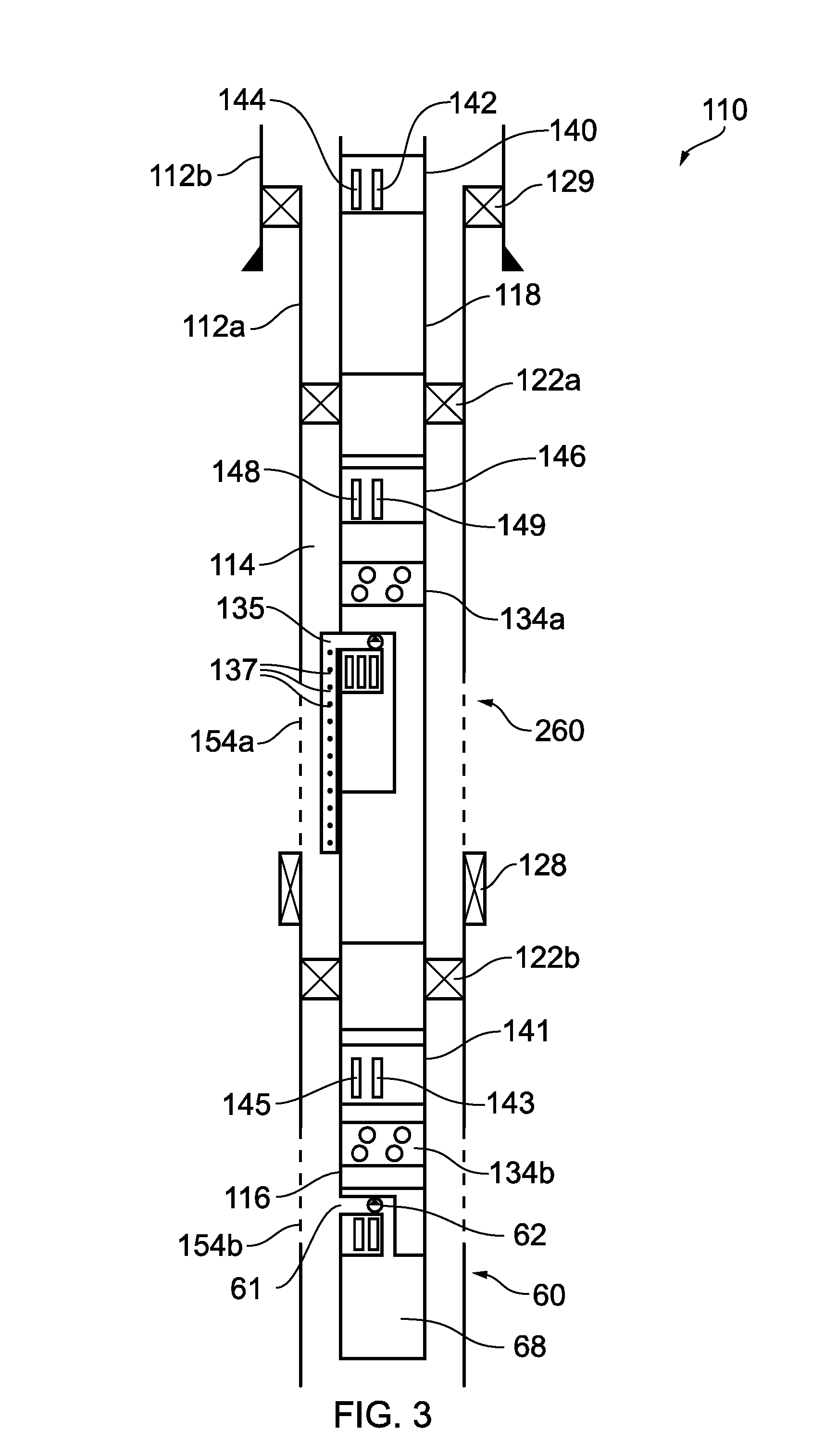
[0162] An array of discrete temperature sensors or a distributed temperature sensor can be provided (for example run in) with the apparatus. Optionally therefore it may be below the annular sealing device. These temperature sensors may be contained in a small diameter (for example 1/4'') tubing line and may be connected to a transmitter or transceiver. If required any number of lines containing further arrays of temperature sensors can be provided. This array of temperature sensors and the combined system may be configured to be spaced out so the array of temperature sensors contained within the tubing line may be aligned across the formation, for example the communication paths; either for example generally parallel to the well, or in a helix shape.
[0163] The array of discrete temperature sensors may be part of the apparatus or separate from it.
[0164] The temperature sensors may be electronic sensors or may be a fibre optic cable.
[0165] Therefore in this situation the additional temperature sensor array could provide data from the communication path interval(s) and indicate if, for example, communication paths are blocked/restricted. The array of temperature sensors in the tubing line can also provide a clear indication of fluid flow, particularly when the apparatus is activated. Thus for example, more information can be gained on the response of the communication paths--an upper area of communication paths may have been opened and another area remain blocked and this can be deduced by the local temperature along the array of the temperature sensors.
[0166] Such temperature sensors may also be used before, during and after pumping the fluid and therefore used to check the effectiveness of the apparatus.
[0167] Moreover, for certain embodiments, multiple longitudinally spaced containers are activated sequentially, and the array of temperature sensors used to assess the resulting flow from communication paths.
[0168] Data may be recovered from the pressure sensor(s), before, during and/or after the pump is operated in response to the control signal. Recovering data means getting it to the surface. Data may be recovered from the pressure sensor(s), before, during and/or after a perforating gun has been activated in the well.
[0169] The data recovered may be real-time/current data and/or historical data.
[0170] Data may be recovered by a variety of methods. For example it may be transmitted wirelessly in real time or at a later time, optionally in response to an instruction to transmit. Or the data may retrieved by a probe run into the well on wireline/coiled tubing or a tractor; the probe can optionally couple with the memory device physically or wirelessly.
Memory
[0171] The apparatus especially the sensors, may comprise a memory device which can store data for recovery at a later time. The memory device may also, in certain circumstances, be retrieved and data recovered after retrieval.
[0172] The memory device may be configured to store information for at least one minute, optionally at least one hour, more optionally at least one week, preferably at least one month, more preferably at least one year or more than five years.
[0173] The memory device may be part of sensor(s). Where separate, the memory device and sensors may be connected together by any suitable means, optionally wirelessly or physically coupled together by a wire. Inductive coupling is also an option. Short range wireless coupling may be facilitated by EM communication in the VLF range.
Well/Reservoir Treatment
[0174] Manipulation of the well may be done by delivering chemical or acid treatment to the well. The chemicals delivered may be a mixture of different substances.
[0175] For certain embodiments therefore, the container comprises a chemical or other fluid to be delivered, such as an acid, and "acid" treatments such as "acid wash" or "acid injection" can be conducted. This may comprise hydrochloric acid or other acids or chemicals used for such so-called acid treatments. The chemical/treatment fluid could be treatment or delivery of the fluids to the well or the formation, such as scale inhibitor, methanol/glycol; or delivering gelling or cutting agents for example bromine trifluoride, breaker fluid, tracer or a chemical or acid treatment.
[0176] The method may be used to clear or extend communication paths or clear the well of any type of debris. This may improve well flow preferably after the isolation from the surface has been removed and/or be used to clear a portion of the well prior to or after perforating or at other times.
[0177] Communication path(s) can be perforations created in the well and surrounding formation by a perforating gun. In some cases, use of a perforating gun to provide communication path(s) is not required. For example the well may be open hole and/or it may include a screen/gravel packs, slotted sleeve or a slotted liner or has previously been perforated. References to communication path(s) herein include all such examples where access to the formation is provided and is not limited to perforations created by perforating guns.
[0178] Acid wash normally treats the face of the wellbore, or may treat scale within a wellbore. Acids may be directed towards the specific communication paths that are damaged, for example by using openings in a tube.
[0179] A conventional acid set-up and treatment conducted from surface is a time-consuming and therefore expensive process. Instead of a conventional acid treatment the method according to the invention may be performed to try to mitigate debris. `Debris` may include perforation debris and/or formation damage such as filter cake.
[0180] The apparatus may be used to deliver chemicals such as tracers or breaker fluids. Chemical barriers may also be deployed, or precursors to a chemical barrier for example cement type material. As an alternative to cement, a solidifying cement substitute such as epoxies and resins, or a non-solidifying cement substitute may be used such as Sandaband.TM.. References herein to cement include such cement substitutes.
[0181] An advantage of such embodiments is being able to deploy chemicals in parts of a well in which it may not be possible to deploy, or viably deploy, using conventional means.
[0182] The method described herein may also be used to conduct a hydraulic fracturing or a minifrac operation.
[0183] In certain embodiments, the apparatus can be used to disrupt, inhibit and/or reverse the settling out and partial solidification of well fluids in parts of the well, especially the annulus.
[0184] The apparatus is suitable for both openhole and perforated sections and can be run with or without a perforation device.
Barrier Test
[0185] The apparatus may be provided below a barrier (such as certain annular sealing devices described herein) and the well manipulated such that a pressure test carried out therebelow, when fluid is deployed. The increased pressure caused by fluid being pumped into this area, stresses the barriers and so can be used to test the upper barrier. Indeed, it stresses it in the direction it is intended to withstand positive pressure, and so is a more effective direction of testing, compared with testing it from above.
[0186] Thus, for some methods, there need not be communication between the formation and the well. For example a pressure test may be conducted in a closed area in the well, for example between barriers or annular sealing devices, i.e. there being no communication paths in the well between the barriers or two annular sealing devices and the adjacent formation.
[0187] For example, a lower barrier bridge or cement plug is typically installed in a well to act as a primary barrier to the reservoir and is exposed, on its lower side, to reservoir pressure. Then a short distance above is a secondary barrier, often another bridge plug or cement plug. Such a secondary barrier can be tested from therebelow in accordance with the procedures set out herein.
[0188] This compares to known methods of reducing the hydrostatic head above such a barrier. This known test is time consuming and removes the safety barrier of the hydrostatic head, compromising well control.
[0189] The apparatus may hang off the secondary barrier.
[0190] The secondary barrier can be set after the apparatus is deployed into the well and charged.
[0191] One or more secondary containers, described herein above, may be provided having an underbalance of pressure. This may be used to test the secondary barrier from below, or to draw in, at least in part, the volume of fluid added from the primary container after a test which added fluid has been completed.
[0192] Similarly, one or more secondary containers, described herein above, may be provided having an overbalance of pressure. This may be used to test the secondary barrier from below, or to replace, at least in part, the volume of fluid removed from the section between the two barriers after a test which removed fluid has been completed.
[0193] A discrete temperature array may be deployed in the section between the barriers, or in a ring or helix above or below the barriers to assist in identifying the location of any leak detected.
Charging Means
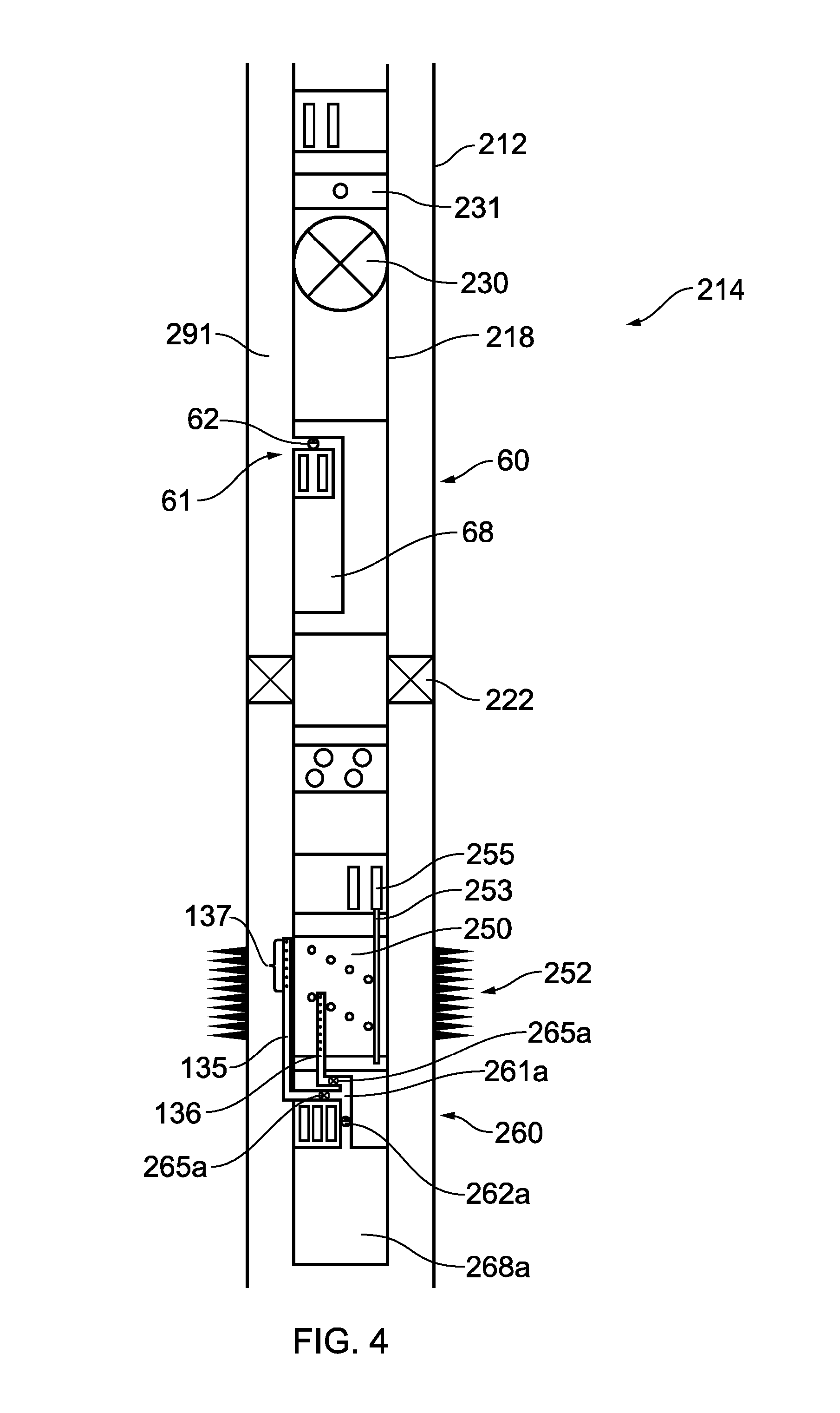
[0194] For certain embodiments including those used for such a barrier test, the apparatus may surprisingly have an in-situ charging means, even though for barrier tests, the pressure surrounding the apparatus is being increased by the pump pumping fluids into this area.
[0195] The charging means comprises a valve controlling a port. Preferred embodiments have a gas separated from the fluid by a floating piston. The valve is opened when pressure surrounding the apparatus is higher than the pressure of the gas. It is therefore charged. The charged gas then acts on the fluid to be deployed into the surrounding portion of the well to assist the pump to deploy the fluids.
[0196] The port may be used to deploy fluid and charge the gas. Alternatively, separate ports may be provided.
[0197] The charging means has some similar features to the pressure balancing means: the port may be a first port, and a second port may be provided in the apparatus between the container and a surrounding portion of the well, the first and second ports separated within the apparatus by a floating piston.
[0198] Where separate ports are provided, the valve may be a one-way valve such that when open, it allows fluid communication from the well into the container, but resists such communication from the container into the well. In a closed position it resists communication in both directions.
[0199] For certain embodiments, the gas is compressed even more, by imposing a pressure from or close to the surface of the well (before the barrier is set) so that the charging means allows for greater compression of the gas. The compressed gas is then sealed in by closing the valve, then at least some of the additional pressure imposed from surface is removed, and the barrier to be tested is set. The gas acts on the fluid to be deployed from the container into the well which facilitates the pump to expel fluids into the surrounding portion of the well.
[0200] However, increasing the well pressure from the surface is not preferred or is limited for certain embodiments, for example where pressure activated tools are present in the well.
[0201] Additionally or alternatively, gas in the apparatus may be pressurised at the surface before it is launched, to similarly facilitate the pump for such an operation or for other applications within the scope of the present invention.
Deployment
[0202] An annular sealing device may or may not be present in the well.
[0203] For certain embodiments, the apparatus may be deployed with an annular sealing device or after an annular sealing device is provided in the well following an earlier operation. In the former case, it may then be provided on the same string as the annular sealing device and deployed into the well therewith. In the latter case, it may be retro-fitted into the well and optionally below the annular sealing device. In this example, it is normally connected to a plug or hanger, and the plug or hanger in turn connected directly or indirectly, for example by tubulars, to the annular sealing device. The plug may be a bridge plug, wireline lock, tubular/drill pipe set barrier, shut-in tool or retainer such as a cement retainer. The plug may be a temporary or permanent plug.
[0204] Also, the apparatus may be provided in the well and then an annular sealing device deployed and set thereabove and then the method described herein performed after the annular sealing device is run in.
[0205] The container may be sealed at the surface, and then deployed into the well. `At surface` in this context is typically outside of the well although it could be sealed whilst in a shallow position in the well, such as up to 30 metres from the surface of the well, that is the top of the uppermost casing of the well. Thus the apparatus moves from the surface and is positioned in the well with the container sealed, before operating the pump. Depending on the particular embodiment and the deployment method, it may be run in a well with no annular sealing device, or with the annular sealing device already thereabove or move past a previously installed annular sealing device.
[0206] For certain embodiments, the entire apparatus may be below the annular sealing device, as opposed to a portion of the apparatus.
[0207] The first port of the apparatus may be provided within 100 m of a communication path between the well and the reservoir, optionally 50 m or 30 m. If there is more than one communication path, then the closest communication path is used to determine the spacing from the first port of the apparatus. Optionally therefore, the first port in the container may be spaced below communication paths in the well.
[0208] In certain embodiments, the apparatus may be run on a tubular string, such as a test, completion, suspension, abandonment, drill, tubing, casing or liner string. Alternatively, the apparatus may also be conveyed into the well on wireline or coiled tubing (or a tractor). The apparatus may be an integral part of the string.
[0209] The apparatus is typically connected to a tubular before it is operated. Therefore whilst it may be run in by a variety of means, such as wireline or tubing, it is typically connected to a tubular such as production tubing or casing when in the well, before it is operated. This provides flexibility for various operations on the well.
[0210] The connection may be by any suitable means, such as by being threaded, gripped, latched etc. onto the tubular. Thus normally the connection between the tubular takes some of the weight of the apparatus, albeit this would not necessarily happen in horizontal wells.
[0211] The apparatus may be provided towards or at the lowermost end of a lowermost casing or liner. The container may be defined, at least in part, by the casing or liner. Therefore the lowermost part of the container may be within 100 m of the bottom of the well and indeed may be the bottom of the casing.
[0212] The string may be deployed as part of any suitable well operation, including drilling, well testing, shoot and pull, completion, work-over, suspension and/or abandonment operation.
[0213] The string may include perforating guns, particularly tubing conveyed perforating guns. The guns may be wirelessly activatable such as from the wireless signals.
[0214] In such a scenario, there may not be straightforward access below guns to the lower zone(s). Thus when run with such a string, embodiments of the invention provide means to pump fluids into such a zone.
[0215] A plurality of apparatus described herein may be run on the same string. For example spaced apart and positioned within a section or isolated sections. Thus, the apparatus may be run in a well with multiple isolated sections adjacent different zones. When the port of the apparatus is isolated from the surface of the well, flow may continue from a separate zone of the well, which is not in pressure communication with the port, and not isolated from the surface of the well.
[0216] The apparatus may be dropped off an associated carrying string after the pump has been operated or for any other reason (for example it is not required and is not possible or useful to return it to surface). Thus it is not always necessary to return it to the surface.
[0217] A variety of arrangements of the apparatus in the well may be adopted. The apparatus may be positioned substantially in the centre of the well. Alternatively the apparatus may be configured as an annular tool to allow well flow through the inner tubular, normally before the well is isolated, after the isolation is removed, or from another section. Therefore, the container is formed in an annular space between two tubes and the well can flow through the inner tube.
[0218] In other embodiments, the apparatus can be offset within the well, for example attached/clamped onto the outside of a pipe or mounted offset within a pipe. Thus it can be configured so apparatus or other objects (or fluid flow) can move through the bore of the pipe without being impeded. For example it may have a diameter of 13/4 inches offset inside a 4'' inner diameter outer pipe. In this way, one or more wireline apparatus can still run past it, as can fluid flow.
[0219] Other apparatus may not provide an arrangement to allow flow past--for example, the container may take up the whole cross-section of the tubing. In one embodiment, below an annular sealing device and beneath communication paths, flow is directed through an annulus between tubing and casing. This may be above or below perforating guns where flow is already normally directed through the tubing/casing annulus.
[0220] For certain embodiments, the apparatus may be deployed in a central bore of a pre-existing tubular in the well, rather than into a pre-existing annulus in the well. An annulus may be defined between the apparatus and the pre-existing tubular in the well.
[0221] The apparatus may be run into the well as a permanent apparatus designed to be left in the well, or run into the well as a retrievable apparatus which is designed to be removed from the well.
Short Interval
[0222] The method to manipulate the well according to the earlier aspects or the third aspect (detailed below) of the invention, may include the method of conducting a short interval test and so the first port may be isolated in a short interval. The pump member can be activated in response to the control signal normally to pump fluid from (or possibly into) the short interval thereby manipulating the well.
[0223] In contrast to the earlier embodiments where the first port of the apparatus is provided between two barriers and pressure tests conducted, the short interval is normally in communication with the reservoir through at least one communication path.
[0224] According to a third aspect of the present invention there is provided a method to manipulate a well by conducting a short interval test, comprising: [0225] providing a pressure sensor in the well; [0226] providing an apparatus in the well, the apparatus comprising a container having a volume of at least 5 litres and a port to allow fluid and optionally pressure communication between a portion of an inside of the container and an outside of the container; [0227] the port of the apparatus being below a first portion of a packer element and above a second portion of a or the packer element, said portions spaced apart from each other by up to 10 m thus defining a short interval, and each engaging with an inner face of casing or wellbore in the well, and being at least 100 m below a surface of the well; [0228] the short interval including at least one communication path between the well and the formation; [0229] the apparatus further comprising: [0230] a pump adapted to move fluid from the surrounding portion of the well into at least a portion of the container via the port; [0231] a control mechanism comprising a communication device configured to receive a control signal for moving the valve member; [0232] deploying the apparatus into the well on a tubular, [0233] sending a control signal from outwith the short interval to the control mechanism at least in part by a wireless control signal transmitted in at least one of the following forms: electromagnetic, acoustic, inductively coupled tubulars and coded pressure pulsing; [0234] operating the pump in response to said control signal to allow fluid to enter the container; and, [0235] drawing in at least 5 litres of fluid into the container from the well.
[0236] In alternative embodiments, pressure in the container may be reduced compared to an outside of the container, such as the surrounding portion of the well, and rather than a pump, a valve can be used to control the reduced pressure in order to draw fluids into the container. Further embodiments have both options.
[0237] The short interval may be defined by one packer element shaped to seal a (relatively small) interval formed from a recess within, or the shape of, the overall packer element. Thus for such embodiments, said first and second portions of a packer element belong to the same packer element. A first packer may therefore include the first and second portions of the packer element, for example a single circular packer element.
[0238] In other embodiments, the short interval is defined between packer elements such as the packer element described more generally herein above and a further packer element. For such embodiments said first and second portions of packer elements are separate packer elements. For such embodiments, a first packer may therefore include the first portion of the packer element, and a second packer may include said second portion, which is a different packer element.
[0239] Thus there can be a second packer element where at least the port of the apparatus is positioned above the second packer element. The entire apparatus may be positioned above said second packer element. The second packer element may be wirelessly controlled. Thus it may be expandable and/or retractable in response to wireless signals.
[0240] Thus in contrast with the first aspect of the invention, the port of the apparatus in the third aspect is below the first packer element (a form of annular sealing device) whereas in the first aspect of the invention the apparatus is below the annular sealing device.
[0241] The short interval, i.e. the distance between two annular sealing devices, may be less than 10 m, optionally less than 5 m or less than 2 m, less than 1 m, or less than 0.5 m. These distances are taken from the lowermost point of the first packer element, and the uppermost point of the second packer element. Thus this can limit the volume and so the apparatus is more effective when the first port is exposed to the limited volume.
[0242] The wireless signal may be sent from outwith the short interval to the control mechanism entirely in its said wireless form.
[0243] Inflatable packers may comprise said packer elements especially for openhole applications. For such openhole applications, the packer elements used in the short interval test may be relatively long, that is 1-10 m, optionally 3-8 m. This is because the pressure drop in the formation may cause flow around the packer element. Increasing the length of the packer element reduces the risk of this occurring.
[0244] In preferred embodiments, fluid to/from the container is pumped gradually over several seconds (such as 5-10 seconds), or longer (such as 2 minutes-6 hours) or even very slow (such as 1-7 days).
[0245] For certain embodiments, such a test can provide an initial indication on the reservoir response to an injection/hydraulic fracturing operation, and may reduce the requirement to conduct a larger scale injection/hydraulic fracturing test.
[0246] Sensors optionally record the pressure especially of the formation for example at the port or outside the apparatus.
[0247] One or both of the packer element(s) may be part of an annular sealing device, described more generally herein.
[0248] The packer(s) may be resettable, so that it/they may be set in a first position and a first test may be performed, then disengaged, moved and reset in a different position, where a second test may be performed. Such a procedure is especially suitable in an openhole section of the well.
[0249] The packer(s) used in a short interval manipulation may also be deployed as part of a drill stem test (DST) string. For example, when performing a drill stem test, a short interval test may be conducted in a section of the well above or below the section being tested in the DST.
[0250] Where space permits, a perforating device such as a perforating gun may be provided in the short interval. This short interval manipulation is also particularly suitable to being performed in an openhole section.
[0251] In order to conduct a short interval test, at least one packer is preferably deployed on a tubular, such as drill pipe, casing and optionally coiled tubing.
[0252] The apparatus may be part of a string which includes a drill bit. The packer(s) may be mounted on said string, and activated to engage with an outer well casing or wellbore.
[0253] There may be a connector, as described herein more generally, connecting the apparatus to the first packer, the connector optionally being above the apparatus and below the first packer element.
[0254] The outside of the container according to the third aspect of the invention is a surrounding portion of the well between the first and second portions of the packer element(s).
[0255] The method described herein may be used to conduct an interval injectivity, permeability, pressure, hydraulic fracturing, minifrac or similar test/manipulation.
[0256] In one embodiment, the well may be manipulated by conducting a flow test. Flow from the reservoir is produced into the short interval, and proceeds through the apparatus. The resulting pump rate can be used to control and/or estimate the flow rate from the reservoir.
[0257] Optional features described above with respect to the first and second aspects of the invention are optional features with respect to the third aspect of the invention. For example, a floating piston and dump chamber are especially useful in embodiments in accordance with the third aspect of the invention. For example the container having volumes of at least 50 litres (l), optionally at least 100 l and optionally a volume of at most 3000 l, normally at most 1500 l, optionally at most 500 l.
Further Procedure
[0258] The method to manipulate the well, may be a method to clear the well especially by delivering fluids such as chemicals, optionally in preparation for a test or further procedure.
[0259] According to a further aspect of the present invention there is provided a method to conduct a procedure or test on a well, comprising: [0260] conducting the method to manipulate the well or formation, as described herein; [0261] conducting a procedure/test on the well, the procedure/test includes one or more of a build-up test, drawdown test, connectivity tests such as an interference test or pulse test, a drill stem test (DST), extended well test (EWT), hydraulic fracturing, mini frac, pressure test, flow test, well/reservoir treatment such as an acid treatment, permeability test, injection procedure, gravel pack operation, perforation operation, image capture, string deployment, workover, suspension and abandonment.
[0262] The test is normally conducted on the well before removing the apparatus from the well, if it is removed from the well.
[0263] Embodiments of said further aspect may improve the pressure or fluid communication across the face of the formation and improve the performance of the tests/procedures. Thus the method of the invention can improve the reliability and/or quality of data received from subsequent testing or improve other procedures.
[0264] The method to conduct a test/procedure on the well may also include perforating the well. However, the method of the present invention may be independent from operation of the guns. The well may be openhole and/or pre-perforated.
[0265] The apparatus may be used to clear the surrounding area, for example by expelling a clear fluid, before images are captured.
[0266] The procedure may be a drill stem test (DST). Thus a DST string and the annular sealing device are deployed as part of the DST. After the final DST flow period or build up has been conducted, a valve controlling flow into the DST test string is closed. The valve is normally below the annular sealing device though for certain embodiments it may be thereabove. The valve may be controlled by said control signals. The portion of the DST string above the valve (often above the annular sealing device) can then, optionally, be removed. The well below the annular sealing device can then be monitored as described herein. Notably the underbalanced container may be activated when required, such as at a much later date. Moreover, communication paths below the annular sealing device between the well and the reservoir need not have been contaminated by kill fluid, and so better connectivity with reservoir can be maintained, providing more useful data when conducting such connectivity tests. If the well is abandoned by cementing above the annular sealing barrier (and normally adding a further barrier) the wireless signals may still be used to monitor the well below the annular sealing device. Data recovery before, during or after the apparatus being activated is normally achieved through wireless signals.
[0267] A pulse test is a type of connectivity test where a pressure pulse is sent from one well/isolate section to another, and the relatively subtle pressure wave detected in the second well. It can then be inferred whether and to what extent the reservoir (or a particular zone) is open and allows pressure communication between these wells/isolated sections. This can be useful to determine the optimum strategy for extracting fluids from the reservoir.
[0268] Another connectivity test is an interference test which monitors longer term affects at an observation well following production (or injection) in a separate well, and useful data can also be obtained regarding the reservoir between the wells or isolated sections, such as connectivity, permeability, and storage capacity.
[0269] For such connectivity tests, the well being manipulated according to embodiments of the present invention is the observing well/sections. Thus the method described herein may include observing for pressure changes in the well/section as part of a connectivity test.
[0270] For certain other embodiments however, the method of manipulating the well may be the well--particularly the isolated section--from where pulses are sent using the apparatus. For example, in a multi-lateral well, the apparatus may send a pressure pulse from one side-track of the same well to another. Side tracks (or the main bore) of wells which are isolated from each other are defined herein as isolated sections.
Miscellaneous
[0271] The well may be a subsea well. Wireless communications can be particularly useful in subsea wells because running cables in subsea wells is more difficult compared to land wells. The well may be a deviated or horizontal well, and embodiments of the present invention can be particularly suitable for such wells since they can avoid running wireline, cables or coiled tubing which may be difficult or not possible for such wells.
[0272] References herein to perforating guns includes perforating punches and drills, which are used to create a flowpath between the formation and the well.
[0273] The surrounding portion of the well, is the portion of the well surrounding the apparatus immediately before the pump is activated in response to the control signal. More precisely it is the pressure of the fluid at or `surrounding` the first port.
[0274] The volume of the container is its fluid capacity.
[0275] Transceivers, which have transmitting functionality and receiving functionality, may be used in place of the transmitters and receivers described herein.
[0276] Unless indicated otherwise, any references herein to "blocked" or "unblocked" includes partially blocked and partially unblocked.
[0277] All pressures herein are absolute pressures unless stated otherwise.
[0278] The well is often an at least partially vertical well. Nevertheless, it can be a deviated or horizontal well. References such as "above" and below" when applied to deviated or horizontal wells should be construed as their equivalent in wells with some vertical orientation. For example, "above" is closer to the surface of the well through the well.
[0279] A zone is defined herein as formation adjacent to or below the lowermost barrier or annular sealing device, or a portion of the formation adjacent to the well which is isolated in part between barriers or annular sealing devices and which has, or will have, at least one communication path (for example perforation) between the well and the surrounding formation, between the barriers or annular sealing devices. Thus each additional barrier or annular sealing device set in the well defines a separate zone except areas between two barriers or annular sealing devices (for example a double barrier) where there is no communication path to the surrounding formation and none are intended to be formed.
[0280] "Kill fluid" is any fluid, sometimes referred to as "kill weight fluid", which is used to provide a hydrostatic head typically sufficient to overcome reservoir pressure.
[0281] Embodiments of the present invention will now be described, by way of example only, with reference to the accompanying figures in which:
[0282] FIG. 1 is a schematic view of a first apparatus which may be used in the method of the present invention;
[0283] FIG. 2 is a schematic view of a second apparatus including a floating piston in accordance with the present invention;
[0284] FIG. 3 is a schematic view of a well with multiple zones, illustrating methods in accordance with the present invention;
[0285] FIG. 4 is a schematic view of a well illustrating further methods in accordance with the present invention;
[0286] FIG. 5 is a schematic view of a further apparatus including a floating piston and a control container in accordance with the present invention;
[0287] FIG. 6a is a schematic view illustrating the FIG. 5 apparatus used in a short interval test in accordance with the present invention;
[0288] FIG. 6b is a schematic view of the apparatus used in a further short interval test in an uncased section of a well;
[0289] FIG. 7 is a schematic view of a further embodiment of the apparatus including a charging means in accordance with the present invention;
[0290] FIG. 8 is an alternative apparatus having a charging means in accordance with the present invention; and,
[0291] FIG. 9 is an alternative apparatus where a well casing defines part of the container.
[0292] FIG. 1 shows an apparatus 60 in accordance with the present invention in the form of a modified pipe, comprising a container 68, a side opening 61, an electrically powered pump 62 in the opening 61, a control mechanism comprising a pump controller 66 and wireless transceiver 64, and a battery 63.
[0293] The pump 62 is configured to pump fluids from/to the container 68 to/from a surrounding portion of the well (outside the apparatus 60) thus selectively allowing fluid communication between a portion of the container 68 and the surrounding portion of the well.
[0294] The pump 62 is controlled by the pump controller 66. The transceiver 64 is coupled to the pump controller 66 and is configured to receive a wireless control signal.
[0295] The components of the control mechanism (the transceiver 64 and the pump controller 66 which controls the pump 62) are normally provided adjacent each other, or close together as shown; but may be spaced apart.
[0296] In the illustrated embodiment, the container 68 comprises liquid 90 to be deployed into the well, and a gas 92, such as nitrogen thereabove. In such embodiments, a wireless signal is received by the transceiver 64 instructing the pump 62 to operate and pump the fluid 90 from the container 68 into the surrounding portion of the well. The gas 92 expands as the liquid 90 is directed into the well.
[0297] In some embodiments, the apparatus 60 can be used for tracer discharge.
[0298] FIG. 2 shows an embodiment of an apparatus 160. Like parts with the FIG. 1 embodiment are not described in detail but are prefixed with a `1`. The apparatus 160 comprises a chamber 168 with a floating piston 174, a dynamic seal 175 between the floating piston 174 and the container's inner bore and a check valve 177 and a pump 162 both provided in an opening 161 to the container 168. Significantly, a pressure balancing port 173 is also provided between the container 168 and the surrounding portion of the well, on the opposite side of the floating piston 174 from the opening 161. A battery 163, transceiver 164 and pump controller 166 are also provided.
[0299] The check valve 177, when in an open position, resists fluid flow from the well into the container 168 but allows fluid flow from the container into the well. The pump 162 is controlled by the pump controller 166. A communication device in the form of a transceiver 164 is coupled to the pump controller 166 and is configured to receive a wireless control signal, such as from an operator at the surface of the well.
[0300] In the present embodiment, the pressure balancing port 173 allows the pump 162 to have a lower rating as it only needs to overcome a relatively small pressure difference to move the fluid between the container 168 and the well; not a larger pressure difference for embodiments without such a port, which also need to overcome the difference in pressure between the container 168 and the well.
[0301] In use, the portion of the container 168 above the floating piston 174 is filled with liquid to be deployed. The sequence begins with the check valve 177 in a closed position and the pump 162 switched off. An operator at the surface of the well sends a wireless signal to the transceiver 164 coupled to the pump controller 166 which instructs the pump 162 to turn on and the check valve 177 consequently opens. The pump 162 then begins moving the liquid from the container 168 above the floating piston 174 into the surrounding portion of the well. As the fluid is expelled from the container 168, fluid from the well enters the chamber 171 via the pressure balancing port 173.
[0302] The rate at which the liquid in the container 168 above the floating piston 174 is expelled into the surrounding portion of the well is controlled by the speed at which the pump 162 operates.
[0303] In other embodiments, the check valve allows fluid flow from the well into the container but resists fluid flow from the container into the well. In such embodiments, the pump directs fluid from the surrounding portion of the well into the container for example, to conduct an inflow test. In such embodiments, the inlet port and pressure balancing port are normally open onto portions of the well isolated from each other.
[0304] In an alternative FIG. 2 embodiment there is no pressure balancing port. However the floating piston is present which seals a gas containing section, from a fluid/liquid containing section which is between the port and the floating piston.
[0305] FIG. 3 shows a multi-zone well 114 comprising a liner hanger 129 and liners 112a and 112b, and two sets of apparatus 260 and 60.
[0306] The apparatus 60 has been previously described. It may be orientated in use as drawn in FIG. 1, or as shown in FIGS. 3 and 4 with a pipe (not shown) within the container 68 provided to draw liquid from a bottom of the container 68 to the opening 61 when the pump 62 operates.
[0307] The apparatus 260 is similar to apparatus 60, 160 and can have the configuration described for apparatus 60 in FIG. 1 or apparatus 160 of FIG. 2. Like parts with earlier embodiments are not described in detail but are prefixed with a `2`.
[0308] Additionally, apparatus 260 also comprises an outlet tube 135, which has multiple openings or outlets 137 through which fluid can be released onto an adjacent upper slotted liner 154a.
[0309] The well 114 has its own well apparatus 110 which comprises two packer elements 122a & 122b which splits the well into a plurality of isolated sections. A first, upper, section comprises the upper packer element 122a, a wirelessly controlled upper sleeve valve 134a, the upper apparatus 260 and the upper slotted liner 154a. The sleeve valve 134a, together with the packer 122a are the isolating components which isolate the port of the apparatus 60a' from the surface of the well.
[0310] A second, lower, section comprises the lower packer element 122b, a wirelessly controlled lower sleeve valve 134b, the lower apparatus 60 and a lower slotted liner 154b. For this second section, the sleeve valve 134b, together with the packer 122b are the isolating components which isolate the port of the apparatus 60a'' from the surface of the well. Moreover, they also function as lower isolating components for the first upper section.
[0311] The slotted liners 154a, 154b create communication paths between the inside of the liner 112a and the adjacent formation.
[0312] Isolating the sections from each other provides useful functionality for manipulating each adjacent zone individually though this is not an essential feature of the invention. For example, the valve 134a in the upper section can be closed to isolate the upper apparatus 60a' from surface of the well, whilst flow continues from the zone adjacent the second lower section.
[0313] The well 114 further comprises a packer such as a swell packer 128 between an outer surface of the liner 112a and a surrounding portion of the formation. The upper tubular 118 and lower tubular 116 are continuous and connected via the upper packer element 122a and the lower packer element 122b. Portions of the upper tubular 118 and lower tubular 116 thus serve as connectors to connect the upper apparatus 260 and lower apparatus 60 to the packer elements 122a, 122b respectively.
[0314] Instrument carriers 140, 141 and 146 are provided in each section and also above the packer element 122a. Each instrument carrier comprises a pressure sensor 142, 143, and 148 respectively, and a wireless relay 144, 145, and 149 respectively.
[0315] In use, fluid flows through the lower slotted liner 154b and into the lower tubular 116 via the lower sleeve valve 134b. The flow continues through the lower tubular 116 past the lower packer element 122b, the upper apparatus 260 and instrument carrier 146 before continuing through the upper tubular 118 towards the surface. The upper apparatus 260 (in contrast to the lower apparatus 60) does not take up the full bore of the upper tubular 118 and so fluid can flow therepast from below without being diverted outside of the upper tubular 118.
[0316] From an upper zone, the well flows through the slotted liner 154a and into the upper tubular 118 via the sleeve valve 134a. The flow continues through the upper tubular 118, past the upper packer element 122a towards the surface.
[0317] The flow may be from the upper zone adjacent the well 114 only, the lower zone adjacent the well 114 only, or may be co-mingled, that is produced from the two zones simultaneously. For example, fluids from the slotted liner 154b combine with further fluids entering the well 114 via the upper slotted liner 154a to form a co-mingled flow.
[0318] The apparatus 260 functions as described for earlier embodiments of the apparatus save that it distributes liquid onto the upper slotted liner 154a. It is activated when the outlets 137 are isolated from the surface of the well such as prior to flowing the well, or after flowing the well. A wireless signal is sent from a controller (not shown) to a pump controller via a transceiver and a pump operates to expel fluid from the container to the surrounding portion of the well (or vice versa). The apparatus 260 is particularly suited to deploying acid for an acid treatment, as it can distribute the fluid over the slotted liner 154a via the tube 135. Optionally pressure in the well can be increased by conventional means to "inject" the acid into the formation.
[0319] The apparatus 60 is activated as previously described.
[0320] Thus embodiments of the apparatus are particularly suited to delivering fluids into the well in a controlled manner such as tracers. Radioactive or chemical tracers may be added and detected elsewhere in the well or at surface, for example to gain more information on fluids produced from separate zones, when co-mingled flow is occurring.
[0321] FIG. 4 illustrates a method of the present invention used during a drill stem test (DST) operation. Two apparatus 60 and 260 are provided in two different sections of a well 214, the sections separated by an annular sealing device in the form of a packer element 222.
[0322] The apparatus 60 is provided above the packer element 222. Above the packer element 222, the well 214 includes a tubing 218 and a casing 212, with an annulus 291 therebetween. A tester valve 230 and a circulation valve 231 are also provided. In use, the annulus 291 between the tubing 218 and the casing 212 above the packer element 222 includes well fluids which may be relatively dense fluid or mud, especially for high pressure wells. The present inventors have noted that under certain circumstances, the mud may become particularly dense and indeed partially solidify, close to the packer element 222, for example as the heavier components settle due to gravity or other forces. The transmission of pressure signals close to or through this substance is more difficult--signals may only be received intermittently or not at all. For example, transmission of signals to a tester 230 or circulation 231 valve can be inhibited.
[0323] The apparatus 60 therefore functions to pump fluid out of the container 68 to disrupt, inhibit and/or reverse the settling out and partial solidification of well fluids in the annulus. Signals to the tester valve 230 or circulation valve 231 above the apparatus 60 are thereafter more reliable.
[0324] A variety of alternatives can be provided. The pump may be operated intermittently so that the disruption can be repeated at spaced apart times. Further containers or indeed apparatus may also be used for the same purpose.
[0325] The apparatus 260 is provided below a perforating gun 250. Two outlet tubes 135, 136 extend from opening 261a of the apparatus 260 over the perforating gun 250. The tubes 135, 136 can have multiple outlets 137 as shown, or alternatively a single outlet, for example to deploy a tracer. Each tube 135, 136 has a valve 265a which can be independently controlled to direct fluid from the container 268a onto selectively different portions of the perforation interval 252. Both tubes 135, 136 are controlled by the same pump 262a. Further valves may be added to provide independent control to each opening. The tubing 218 and perforating gun 250 serve as a connector to connect the apparatus 260 to the annular sealing device 222.
[0326] A discrete temperature array 253 is provided adjacent to the perforations 252 and connected to a controller 255. In this embodiment the discrete temperature array has multiple discrete temperature sensors along the length of a small diameter tube.
[0327] After isolation from the surface of the well, the apparatus 260 is activated wirelessly causing the pump 262a to start, which can direct fluid, such as acid or tracer, onto the perforations.
[0328] The two apparatus 60, 260 illustrated in FIGS. 3 and 4 can be used independently of each other in single or multiple zone wells and are illustrated in the same figure and same well for brevity.
[0329] A further embodiment 360 of apparatus suitable for use in the method of the invention is shown in FIG. 5. Like parts with earlier embodiments are not described in detail but are prefixed with a `3`.
[0330] The apparatus 360 comprises a container 368 having a floating piston 374 with seals 375 and a pump 362. A valve 377 (optionally a check valve) is provided in an opening 361 of the container 368.
[0331] The apparatus 360 also comprises other components which are not shown, including a battery, a pump controller and a transceiver for wireless signals.
[0332] In contrast to the FIG. 2 embodiment, the pump 362 is provided in a central portion, between the container 368 and a control container 380. The control container 380 has a second floating piston 382, along with seals 383; and below the second floating piston 382 a port 373 is provided to allow a pressure balance between the control container below the second floating piston 382 and the surrounding portion of the well.
[0333] A control fluid is provided above the second floating piston 382 whilst a fluid to be expelled is provided in the container 368 above the floating piston 374. In use, a wireless signal is sent to the pump 362 via the transceiver and pump controller, and the pump 362 pumps control fluid from the control container 380 into the container 368, below the floating piston 374. This in turn moves the floating piston 374 and expels the fluid in the container 368 to the surrounding portion of the well.
[0334] The pump 362 can also operate in a reverse direction to that described. The control fluid is pumped from the container 368 below the floating piston 374 into the control container 380 thus drawing well fluids into the container 368 above the floating piston 374.
[0335] The apparatus 360 can be cycled between expelling and drawing in fluids indefinitely. An advantage of such an apparatus is that the pump pumps a `clean` control fluid rather than the well fluids which are much more variable in their physical properties which may affect the flow rate and any related data.
[0336] In alternative embodiments, rather than a port 373 allowing pressure balance, the section below the second floating piston may be sealed and pre-charged with gas under pressure.
[0337] FIG. 6a shows one application of the FIG. 5 apparatus for use with a short interval test using the apparatus 360. The packers 322a and 322b are set in the casing 312, and a perforating tool 350 receives a wireless signal to activate and punch a hole 352 in the casing 312 and adjacent formation 351.
[0338] The apparatus 360 then receives a control signal to start the pump 362 to pump control fluid from the control container 380 into the container 368 below the piston 374, which in turn expels fluids in the container 368 above the piston 374. In this way, an injection test can be carried out, during which the build-up of pressure can be monitored using pressure sensor(s). Data from the pressure sensor(s) can be transmitted wirelessly, for example by acoustic or electromagnetic signals, to the surface to monitor the results of the test.
[0339] Optionally a tube with multiple exits can be provided at the opening 361 to distribute fluids over an area, such as a plurality of communication paths.
[0340] Optionally the pump 362 can be reversed to draw in fluids from the well. Moreover, a variety of alternatives are available for such a procedure. In one embodiment, the pump 362 can be stopped and started before the container 368 has expelled its contents (or if operating in reverse, before it has been filled with well fluid) and this start/stop sequence can be repeated. In one embodiment, an operator can unseat the packers 322a, 322b, reposition the apparatus 360, re-seat the packers 322a, 322b, and then conduct the procedure again.
[0341] In one alternative embodiment, a second container is provided at a different pressure to the surrounding portion of the well, for example it may be underbalanced. This may be activated to, for example, purge the surrounding area of debris before the apparatus 360 is operated. Such a further container having a different pressure, may be combined with other embodiments described herein.
[0342] FIG. 6b shows a similar short interval test using a well apparatus 310b, apparatus 360b in an uncased/openhole section of well 315.
[0343] In this embodiment a single packer 322c is provided with an opening 394 aligned with a port 361b of the apparatus and so a portion of the packer is above the port 361b and a portion of the packer is below the port 361b, thus isolating a short interval. The apparatus 360b also comprises a pump 362b and a valve 377b in close proximity to each other. A pressure gauge 395b monitors the pressure of the interval and is powered by a battery 363b.
[0344] The short interval test or other manipulation can be conducted following the same procedure described with respect to FIG. 6a.
[0345] In certain situations, it may be useful to control the interval for instance to add `kill` fluid. Optionally therefore, a sleeve valve 330 can be provided between the tubing string 318 and surrounding annulus 291A which can be opened to allow pressure connectivity between the interval and the string above, for example to allow kill fluid to enter the interval.
[0346] Certain embodiments of the invention may be used to conduct a barrier test in a well. They are placed beneath the sealed barrier, and then expel fluids in order to increase the volume below the barrier and so stress the barrier in order to test it.
[0347] FIG. 7 shows apparatus 460a with a charging means in accordance with the present invention and which is particularly suited to such barrier tests. Like parts with earlier embodiments are not described in detail but are prefixed with a `4`.
[0348] The apparatus 460a, comprises a container 468a, a pump 462a in a port 461a and a side port 473a with a valve 477a. The container has a floating piston 474a separating a first liquid containing section 491a from a second gas containing section 492a.
[0349] In use, the apparatus 460a may be deployed with the floating piston 474a positioned such that around three quarters of the container 468a is the gas containing section 492a and around one quarter is the liquid containing section 491a. As the apparatus is moved deeper into the well, the increased well pressure, will cause movement of the floating piston 474a and compression of the gas.
[0350] The apparatus is positioned below the barrier to be tested, with the valve 477a open and well fluids are received into the first section 491a of the container 468a compressing or `charging` the gas in the second section 492a to the surrounding well pressure. The valve 477a is then closed.
[0351] When the barrier (not shown) is in place, the pump 462a is operated to pump the fluid from the first section 491a of the container 468a into the surrounding portion of the well. The compressed gas in the second section 492a of the apparatus 460a acts on the liquid in the first section 491a so that it is substantially at well pressure before the further action of the pump 462a, thus facilitating the pump 462a to operate (compared to pumping a liquid having an atmospheric pressure). In this way, a lower pump rating may be used.
[0352] The barrier can be formed before or after the apparatus is charged.
[0353] For certain embodiments, the pressure may be stored as described when the well pressure is increased from the surface, which will further charge the apparatus. This may be done by applying pressure or before circulating heavy fluids in the well's hydrostatic head for lighter fluids. It may take advantage of the well pressure changing for some other reason/operation or be done intentionally to increase the charge to the apparatus. In such circumstances, the charging would normally take place before the barrier is set.
[0354] FIG. 8 shows an apparatus 460b which is a modified version of the apparatus 460a where the charging means facilitates deploying a specific fluid in the well (for example acid). Like parts will not be described again in detail but will be suffixed with a `b` rather than an `a`.
[0355] In common with the FIG. 7 embodiment, the FIG. 8 apparatus 460b comprises a pump 462b in a port 461b, a floating piston 474b within a container 468b, a first liquid containing section 491b and a second gas containing section 492b.
[0356] In contrast to the FIG. 7 embodiment, a valve 477b in the apparatus 460b is provided in a second port 473b at an opposite end to the pump 462b. Moreover a second floating piston 482b is provided in the container 468b between the second port 473b and the first floating piston 474b, to define a third `charging` section 493b of the container 468b.
[0357] The apparatus 460b can be similarly charged via the second port 473b and the apparatus 460b operated in the same manner as that described above with respect to apparatus 460a. A benefit of the FIG. 8 apparatus over the FIG. 7 apparatus is that the liquid expelled from the liquid containing section 491b can be chosen for an alternative (or additional) purpose than pressure testing, for example acid treatment, rather than using liquid from the well.
[0358] In FIG. 9 an alternative embodiment of an apparatus 560 with a container 568 is illustrated. Common features, for example pump 565 and valve 562, with earlier embodiments are not described again in detail for brevity but use the same latter two digits as reference numerals with a `5` prefix. In contrast to earlier figures the container 568 is in part defined by the surrounding casing 512 and outlet tube 535 with openings 537 is secured to a portion of the casing 512 above the container 568 by clamps 596. Such an apparatus 560 is normally run on the casing 512 when completing the well. An advantage of such an embodiment is that the container can have larger volumes without running further tubing into the well. The apparatus 560 may have flow bypass 597 for cementing during completion or for circulating during deployment. Such embodiments are useful for deploying treatments to a toe of a deviated well.
[0359] It will be appreciated that the method according to the invention can be carried out using a variety of apparatus 60, 160, 260, 360, 360b, 460a, 460b, 560 and the examples using these different apparatus in different contexts are not limiting, and the different apparatus can be used in the different positions shown in the FIGS. 3, 4, 6a, 6b and 9 wells.
[0360] Modifications and improvements can be incorporated herein without departing from the scope of the invention. For example various arrangements of the container and electronics may be used, such as electronics provided in the apparatus below the container.
* * * * *
D00000
D00001
D00002
D00003
D00004
D00005
D00006
D00007
D00008
D00009
D00010
XML
uspto.report is an independent third-party trademark research tool that is not affiliated, endorsed, or sponsored by the United States Patent and Trademark Office (USPTO) or any other governmental organization. The information provided by uspto.report is based on publicly available data at the time of writing and is intended for informational purposes only.
While we strive to provide accurate and up-to-date information, we do not guarantee the accuracy, completeness, reliability, or suitability of the information displayed on this site. The use of this site is at your own risk. Any reliance you place on such information is therefore strictly at your own risk.
All official trademark data, including owner information, should be verified by visiting the official USPTO website at www.uspto.gov. This site is not intended to replace professional legal advice and should not be used as a substitute for consulting with a legal professional who is knowledgeable about trademark law.