Multicomponent Latent-crimping Staple Fiber And Method Therefor
DUGAN; Jeffrey S.
U.S. patent application number 16/176835 was filed with the patent office on 2019-05-02 for multicomponent latent-crimping staple fiber and method therefor. The applicant listed for this patent is Fiber Innovation Technology, Inc.. Invention is credited to Jeffrey S. DUGAN.
| Application Number | 20190127891 16/176835 |
| Document ID | / |
| Family ID | 66243533 |
| Filed Date | 2019-05-02 |


| United States Patent Application | 20190127891 |
| Kind Code | A1 |
| DUGAN; Jeffrey S. | May 2, 2019 |
MULTICOMPONENT LATENT-CRIMPING STAPLE FIBER AND METHOD THEREFOR
Abstract
A multicomponent latent-crimping staple fiber, or a non-mechanically-crimped staple fiber contains a first component and a second component which each have their own differing lengths and a shrinkage differential therebetween and eccentric cross-sectional centers of mass. The staple fibers herein have a tenacity after crimping of at least 90% as compared to the tenacity prior to crimping. Processes for making such a fiber are also described.
| Inventors: | DUGAN; Jeffrey S.; (Erwin, TN) | ||||||||||
| Applicant: |
|
||||||||||
|---|---|---|---|---|---|---|---|---|---|---|---|
| Family ID: | 66243533 | ||||||||||
| Appl. No.: | 16/176835 | ||||||||||
| Filed: | October 31, 2018 |
Related U.S. Patent Documents
| Application Number | Filing Date | Patent Number | ||
|---|---|---|---|---|
| 62579190 | Oct 31, 2017 | |||
| Current U.S. Class: | 1/1 |
| Current CPC Class: | D02G 1/18 20130101; D01F 8/12 20130101; D01D 5/22 20130101; D01F 8/06 20130101; D01D 5/32 20130101; D01F 8/16 20130101; D01F 8/14 20130101 |
| International Class: | D01F 8/12 20060101 D01F008/12; D01F 8/16 20060101 D01F008/16; D01F 8/14 20060101 D01F008/14; D01F 8/06 20060101 D01F008/06; D02G 1/18 20060101 D02G001/18 |
Claims
1. A multicomponent latent-crimping staple fiber comprising: A. a first component comprising: i. a first length; and ii. a first cross-sectional center of mass; and B. a second component comprising: i. a second length; and ii. a second cross-sectional center of mass, wherein the shrinkage differential between the first length and the second length is at least 0.01%, and wherein the first cross-sectional center of mass and the second cross-sectional center of mass are eccentric, wherein the first component and the second component are extruded and combined to form a multicomponent latent-crimping fiber, wherein the multicomponent latent-crimping fiber is cut to form a multicomponent latent-crimping staple fiber, wherein the multicomponent latent-crimping staple fiber is crimped either before, during, or after cutting, and wherein the multicomponent latent-crimping staple fiber has a tenacity of at least about 90% as compared to the tenacity of the multicomponent latent-crimping fiber prior to crimping.
2. The multicomponent latent-crimping staple fiber according to claim 1, wherein the first component comprises a polymer selected from the group consisting of a polyamide, a sulfur-containing polymer, an aromatic polyester, an aliphatic polyester, a polyolefin, and a combination thereof.
3. The multicomponent latent-crimping staple fiber according to claim 1, wherein the second component comprises a polymer selected from the group consisting of a polyamide, a sulfur-containing polymer, an aromatic polyester, an aliphatic polyester, a polyolefin, and a combination thereof.
4. The multicomponent latent-crimping staple fiber according to claim 1, wherein the multicomponent latent-crimping staple fiber is selected from a heat-crimped fiber, a humidity-crimped fiber, a water-crimped fiber, a light-crimped fiber, and a combination thereof.
5. The multicomponent latent-crimping staple fiber according to claim 1, wherein the multicomponent latent-crimping fiber is extruded and drawn to optimize tenacity
6. The multicomponent latent-crimping staple fiber according to claim 1, wherein the tenacity is the tenacity at break.
7. The multicomponent latent-crimping staple fiber according to claim 1, wherein the tenacity is the tenacity at 7% elongation.
8. (canceled)
9. The multicomponent latent-crimping staple fiber according to claim 1, wherein the first component comprises nylon, wherein the second component comprises nylon, wherein the tenacity at break prior to crimping is at least 5.5 g/denier, wherein the tenacity at 7% elongation prior to crimping is at least 1.3 g/denier, wherein the tenacity at break after crimping is at least 90% of the tenacity at break prior to crimping, and wherein the tenacity at 7% elongation after crimping is at least 90% of the tenacity at 7% elongation prior to crimping.
10. A fabric comprising the multicomponent latent-crimping staple fiber according to claim 1.
11.-14. (canceled)
15. A non-mechanically-crimped staple fiber comprising: A. a first component comprising: i. a first length; and ii. a first cross-sectional center of mass; and B. a second component comprising: i. a second length; and ii. a second cross-sectional center of mass, wherein the shrinkage differential between the first length and the second length is at least 0.01%, and wherein the first cross-sectional center of mass and the second cross-sectional center of mass are eccentric, wherein the first component and the second component are extruded to form a non-mechanically-crimped fiber, wherein the non-mechanically-crimped fiber is cut to form a non-mechanically-crimped staple fiber, wherein the non-mechanically-crimped fiber is crimped either before, during, or after cutting, and wherein the non-mechanically-crimped staple fiber has a tenacity of at least about 90% as compared to the tenacity of the non-mechanically-crimped fiber prior to crimping.
16. The non-mechanically-crimped staple fiber according to claim 15, wherein the first component comprises a polymer selected from the group consisting of a polyamide, a sulfur-containing polymer, an aromatic polyester, an aliphatic polyester, a polyolefin, and a combination thereof.
17. The non-mechanically-crimped staple fiber according to claim 15, wherein the second component comprises a polymer selected from the group consisting of a polyamide, a sulfur-containing polymer, an aromatic polyester, an aliphatic polyester, a polyolefin, and a combination thereof.
18. The non-mechanically-crimped staple fiber according to claim 15, wherein the multicomponent latent-crimping staple fiber is selected from a heat-crimped fiber, a humidity-crimped fiber, a water-crimped fiber, a light-crimped fiber, and a combination thereof.
19. The non-mechanically-crimped staple fiber according to claim 15, wherein the multicomponent latent-crimping fiber is extruded and drawn to optimize tenacity
20. The non-mechanically-crimped staple fiber according to claim 15, wherein the tenacity is the tenacity at break.
21. The non-mechanically-crimped staple fiber according to claim 15, wherein the tenacity is the tenacity at 7% elongation.
22. The non-mechanically-crimped staple fiber according to claim 15, wherein the first component is nylon 6, 6, with a relative viscosity of from about 30 to about 60, wherein the second component is nylon 6, 6, with a relative viscosity of from about 50 to about 130, and wherein the relative viscosity of the second component is at least 20 higher than the relative viscosity of the first component.
23. The non-mechanically-crimped staple fiber according to claim 15, wherein the tenacity at 7% elongation is at least 1.3 g/denier prior to non-mechanically crimping, and wherein the tenacity at 7% elongation after non-mechanically-crimping is at least 70% of the tenacity at 7% elongation prior to non-mechanically crimping.
24. The non-mechanically-crimped staple fiber according to claim 15, wherein the tenacity at break is at least 5.5 prior to non-mechanically crimping, and wherein the tenacity at break after non-mechanically-crimping is at least 70% of the tenacity at break prior to non-mechanically crimping.
25. The non-mechanically-crimped staple fiber according to claim 15, wherein the first component, the second component, or both the first component and the second component comprises a polyphenylene sulfide.
26. The non-mechanically-crimped staple fiber according to claim 15, wherein the first component comprises nylon, wherein the second component comprises nylon, wherein the tenacity at break prior to crimping is at least 5.5 g/denier, wherein the tenacity at 7% elongation prior to crimping is at least 1.3 g/denier, wherein the tenacity at break after crimping is at least 90% of the tenacity at break prior to crimping, and wherein the tenacity at 7% elongation after crimping is at least 90% of the tenacity at 7% elongation prior to crimping.
27. A fabric comprising the non-mechanically-crimped staple fiber according to claim 15.
28. A garment comprising the non-mechanically-crimped staple fiber according to claim 15.
Description
CROSS-REFERENCE TO RELATED APPLICATIONS
[0001] This application claims the benefit of U.S. Provisional Application No. 62/579,190 filed Oct. 31, 2017, the disclosure of which is incorporated by reference in its entirety.
FIELD OF THE INVENTION
[0002] The present invention relates to artificial (a.k.a., synthetic or man-made) fibers. More specifically, the present invention relates to self-crimping or latent-crimping artificial fibers.
BACKGROUND
[0003] Artificial fibers are typically spun, drawn, and textured prior to being spun into a yarn. Often such artificial fibers are textured by crimping prior to use as crimping provides benefits such as improved skin feel, softness, stretch, fluffiness, etc. to the fibers. Crimping may also be required in order to card/spin the fibers into a yarn. Traditionally, crimping is achieved via a mechanical crimping tool or machine (e.g., a stuffer-box crimper) which physically compresses some parts of the fiber so as to achieve a wavy pattern in the fiber. Such crimps typically form such a wavy pattern by forming a sharp bend in the fiber at various intervals. However, it has now been found that such sharp bends and deformation of the fiber results in reduced fiber strength.
[0004] Multicomponent, latent-crimp artificial fibers formed from polymers are known. Such artificial fibers tend to be synthetic fibers formed of man-made polymers such as polyethylene, polypropylene, polyurethanes, polyesters, etc., and the latent-crimping is typically formed by using, for example, polymers of different viscosities, different melt temperatures, different thicknesses, different fiber shapes, etc. which then form crimps or in some cases, a continuous curl(s) in the case of many latent-crimping fibers, when the fibers are exposed to heat, humidity, mechanical stretching, etc. Such artificial fibers are typically long fibers, such as tow fibers, continuous filament yarns, etc. The typical goal of such latent-crimp fibers is to increase fiber bulk without having to mechanically crimp the fibers thereby avoiding a processing step, and/or avoiding a step which limits the throughput speed. Other times there may be a desire to cause the fiber to curl after a fabric is formed, so as to develop bulk in the fabric.
[0005] Such multicomponent, latent-crimp artificial fibers may be used in, for example non-woven fabrics, spun-bound fabrics, and the like as well as yarns, and woven fabrics. These may then be further processed into a variety of products ranging from garments to carpeting, diapers, drapes, personal care items, industrial components, tires, linens, etc.
[0006] While bulk and fluffiness are typically an important characteristic of artificial fibers, depending on the intended use, additional characteristics such as hydrophobicity, hydrophilicity, tenacity, acid resistance, colorability, stain resistance, durability to laundering, abrasion resistance, etc. may also be desirable. However, current multicomponent, latent-crimp fibers do not have very high tenacity. Furthermore, typical latent-crimp fibers do not consist of exclusively polyamide fibers but may instead include a selection of many polymers.
[0007] In certain specialized fabric applications such as military apparel, protective apparel, workwear, etc., fibers may require both high tenacity as well as abrasion resistance. Abrasion resistance, at least in polyamides, is typically correlated with tenacity, and is understood to be caused by a high tenacity, or more precisely, caused by the same molecular morphology within the fiber that results in a high tenacity. However, current multicomponent latent-crimp artificial fibers may suffer problems such as low tenacity, expensive equipment requirements, complex processing steps, etc. Without intending to be limited by theory, it is believed that previous processes have not sought to optimize the tenacity of the fibers using various techniques, formulas, etc. while also forming a latent-crimping fiber. We further believe that such a process has not been optimized in the production of a staple fiber process.
[0008] Continuous filament processes typically do not use stuffer-box crimping because the continuous filament processes typically need to run at speeds above those at which stuffer-box crimping can effectively operate. So continuous filament processes typically rely on latent crimping or use hot air and agitation in a process common in carpet yarns, known as "bulked continuous filament" (BCF) processes. In some continuous filament processes, a mechanical texturizing process also imparts discrete bends into the fibers.
[0009] In contrast, staple fiber processes typically do not use latent crimping because they are slow enough to accommodate stuffer-box crimping which is technically easier and standard in the industry. Staple fibers will typically be carded and thus require crimping less for softness than for their ability to hold together in and after the carding process because of the crimping. Other existing staple fibers require mechanical crimping, which has now been found to result in a loss of tenacity as compared to the original fiber. Similarly, existing commercial nylon staple fibers and yarns made therefrom, such as those that are "micro-kinked" (e.g., "Type 420" high tenacity nylon 6, 6 by Invista) are high-tenacity staple fibers that are reportedly neither latent-crimped nor fully-mechanically-crimped. Allegedly these micro-kinked fibers are produced via an expensive and unwieldy process which is responsible for imparting the micro-kinks. However, because these fibers are not crimped nor curled in the conventional sense, they cannot be carded by themselves without loading the card. Instead, the micro-kinked fibers must be blended with, for example, cotton so that the naturally crimped cotton fibers will carry the fibers through the card. And even so, even these fibers do require a minimum amount of crimp, imparted in a reportedly expensive and unwieldy "micro-kinking" process.
[0010] Accordingly, there remains a need for staple fibers having a latent crimp that possess improved tenacity, lower production costs, reduced complexity, and/or that can be made with standard staple fiber production equipment and simpler, less expensive, and less labor-intensive production processes. The need also exists for high-tenacity polyamide fibers such as nylon, that possess a latent crimp. The need also exists for a high-tenacity staple fiber which is suitable for carding and does not require blending with other crimped fibers.
SUMMARY OF THE INVENTION
[0011] In an embodiment of the present invention, a multicomponent latent-crimping staple fiber contains a first component and a second component. The first component has a first length and a first cross-sectional center of mass. The second component has a second length and a second cross-sectional center of mass. The shrinkage differential between the first length and the second length is at least 0.01%, based on the lower shrinkage rate polymer component. The first cross-sectional center of mass and the second cross-sectional center of mass are eccentric. Furthermore, the first component and the second component are extruded to form a multicomponent latent-crimping fiber, and the multicomponent latent-crimping fiber is cut to form a multicomponent latent-crimping staple fiber. The multicomponent latent-crimping staple fiber is crimped either before, during, or after cutting, and the multicomponent latent-crimping staple fiber has a tenacity of at least about 90% as compared to the tenacity of the multicomponent latent-crimping fiber prior to crimping.
[0012] In an embodiment of the present invention, a method for forming a staple fiber contains the steps of melting a first component, melting a second component, combining the first component with the second component, extruding the first component and the second component from an extrusion die to form a fiber, drawing the fiber to form a drawn fiber, non-mechanically crimping the drawn fiber to form a crimped fiber, and cutting the fiber to form a staple fiber. In this process, the extruding step may occur before the combining step, after the combining step, or simultaneously with the combining step. In addition, the cutting step may be occur before or after the non-mechanically crimping step.
[0013] In an embodiment of the present invention, a non-mechanically-crimped staple fiber contains a first component and a second component. The first component has a first length and a first cross-sectional center of mass. The second component has a second length and a second cross-sectional center of mass. The shrinkage differential between the first length and the second length is at least 0.01%, based on the lower shrinkage rate polymer component and the first cross-sectional center of mass and the second cross-sectional center of mass are eccentric. The first component and the second component are extruded to form a non-mechanically-crimped fiber. The non-mechanically-crimped fiber is cut to form a non-mechanically-crimped staple fiber, where the non-mechanically-crimped fiber is crimped either before, during, or after cutting. The non-mechanically-crimped staple fiber has a tenacity of at least about 90% as compared to the tenacity of the non-mechanically-crimped fiber prior to crimping.
[0014] Without intending to be limited by theory it is believed that the present invention may provide, for example, a multicomponent or non-mechanically-crimped staple fiber which is cardable without mechanical crimping, a multicomponent or non-mechanically-crimped staple fiber which has a higher tenacity than a comparable mechanically-crimped fiber, a process with improved speed, a process with reduced complexity, a process which allows high tenacity staple fibers to be made with standard equipment, a process that avoids the expense and complexity of micro-kinking, a less labor-intensive process, and/or a multicomponent or non-mechanically-crimped staple fiber which is more easily blended with other fibers. It is further believed that these fibers, multicomponent staple fibers, non-mechanically-crimped staple fibers, etc. are especially suitable for use in fabrics which require a high tenacity, such as protective garments and work clothes.
BRIEF DESCRIPTION OF THE DRAWINGS
[0015] FIG. 1 shows a cross-sectional view of an embodiment of a fiber of the present invention having a dumbbell-shaped cross-section;
[0016] FIG. 2 shows a cross-sectional view of an embodiment of a fiber of the present invention having a circular-shaped cross-section;
[0017] FIG. 3 shows a cross-sectional view of as embodiment of a fiber of the present invention having a circular-shaped cross-section;
[0018] FIG. 4 shows a cross-sectional view of an embodiment of a fiber of the present invention having a snowman-shaped cross-section;
[0019] FIG. 5 shows a cross-section view of an embodiment of a fiber of the present invention having a bowtie-shaped cross-section;
[0020] FIG. 6 shows a cross-sectional view of an embodiment of a fiber of the present invention having a trilobal-shaped cross-section;
[0021] FIG. 7 shows a cross-sectional view of an embodiment of a fiber of the present invention having an oval-shaped cross-section;
[0022] FIG. 8 shows a cross-sectional view of an embodiment of a fiber of the present invention having an oval-shaped cross-section;
[0023] FIG. 9 shows a cross-sectional view of an embodiment of a fiber of the present invention having a circular-shaped cross-section and multiple components therein;
[0024] FIG. 10 shows a perspective view of an embodiment of a fiber of the present invention; and
[0025] FIG. 11 shows a simplified view of an embodiment of a fiber showing the aggregate center of mass.
[0026] The figures herein are for illustrative purposes only and are not necessarily drawn to scale.
DESCRIPTION OF THE PREFERRED EMBODIMENTS
[0027] Unless otherwise specifically provided, all tests herein are conducted at standard conditions which include a room and testing temperature of 25.degree. C., sea level (1 atm.) pressure, pH 7, 35% relative humidity, and all measurements are made in metric units. Furthermore, all percentages, ratios, etc. herein are by weight, unless specifically indicated otherwise.
[0028] As used herein, the term "shrinkage differential", .DELTA.S, indicates the percent difference in length of the polymer component occupying the inner surface of the helix formed by the curled fiber and the polymer component occupying the outer surface of the helix formed by the curled fiber, divided by the length of the polymer component occupying the outer inner surface of the helix formed by the curled fiber. As one skilled in the art understands, when these are extruded/combined, these polymers have the same length. However, upon being non-mechanically-crimped, either by heat, humidity, etc. as described herein, one polymer component will shrink more than the other polymer component, thereby causing the entire fiber to curl and form a helix. Without intending to be limited by theory, it is believed that in such a situation, the polymer component which shrinks more will be on the inside/inner part of the helix while the polymer component which shrinks less will necessarily be on the outside/outer part of the helix.
[0029] As used herein, the term "mechanical crimping" and variations thereof such as "mechanically-crimped", refers to crimping caused by the physical compression of at least a portion of the fiber, typically with a gear-like roller, zig-zag or wavy teeth, a machine such as a stuffer-box crimper, and other mechanical methods and equipment known in the fiber and textile art. In some cases, a bulked continuous filament (BCF) process may also include mechanical crimping therein so as to bulk up the filament and make it fatter, fluffier, etc.
[0030] As used herein, the term "latent-crimping" indicates that the fiber is designed and formed in a manner such that it may be crimped without the use of mechanical crimping. Such latent-crimping is known in the art and may be caused by, for example, applying heat, humidity, water, etc. to the fiber which causes the (properly-configured) fiber to curl or crimp.
[0031] As used herein, the term "eccentric" indicates that the (first, second, etc.) cross-sectional centers of mass are not at the same point.
[0032] As used herein the term "yarn" typically indicates a collection or a plurality of continuous filaments and/or staple fibers held together as a bundle, roughly in parallel. The yarn typically has a substantially continuous length, such as a length greater than about 25 cm, and more typically a length of from about 1 meter to even about 10,000,000 meters or more.
[0033] As used herein, it is understood herein that Nomex.TM. by DuPont is generally representative of meta-aramid polymer fibers, while Kevlar.TM. by DuPont is generally representative of para-aramid polymer fibers.
[0034] An embodiment of the present invention relates to a multicomponent latent-crimping staple fiber containing a first component and a second component. The first component has a first length and a first cross-sectional center of mass. The second component has a second length and a second cross-sectional center of mass. The shrinkage differential, .DELTA.S, is the percentage difference of the first length and the second length, as described herein, and is at least 0.01%. For an explanation about the shrinkage differential and the calculation thereof, please see FIG. 10 and the discussion therefor. Also, the first cross-sectional center of mass and the second cross-sectional center of mass are eccentric.
[0035] It is further understood that in a multicomponent fiber, the components are typically arranged in the fiber such that they define a specific spatial arrangement within the fiber's cross section. Furthermore, this specific spatial arrangement typically does not vary significantly along the entire length of the fiber. As a result, any discussion of centers of mass of the components in such a multi-component fiber defines a specific cross-sectional arrangement, and not a specific feature that involves changes in the fiber's cross section along its length.
[0036] Another embodiment of the present invention relates to a non-mechanically-crimped staple fiber containing a first component and a second component. The first component has a first length and a first cross-sectional center of mass. The second component has a second length and a second cross-sectional center of mass. The shrinkage differential between the first length and the second length is at least 0.01%, based on the lower shrinkage rate polymer component. Also, the first cross-sectional center of mass and the second cross-sectional center of mass are eccentric.
[0037] Another embodiment of the present invention relates to a method of forming a staple fiber by the steps of melting a first component, melting a second component, combining the first component with the second component, extruding the first component and the second component from an extrusion die to form a fiber, drawing the fiber to form a drawn fiber, non-mechanically crimping the drawn fiber to form a crimped fiber, and cutting the crimped fiber to form a staple fiber. In this process, the extruding step may occur before the combining step, after the combining step, or simultaneously with the combining step. As used herein, the "combining step" indicates where different molten polymer streams and/or fibers/streams extruded from the spinnerets are combined together to form a single fiber. If the combining step occurs when the polymer streams are molten, then this typically occurs immediately before, or simultaneously with, the extruding step.
[0038] Another embodiment of the present invention relates to a method of forming a staple fiber by the steps of melting a first component, melting a second component, combining the first component with the second component, extruding the first component and the second component from an extrusion die to form a fiber, drawing the fiber to form a drawn fiber, cutting the drawn fiber to form a cut fiber, and non-mechanically crimping the cut fiber to form a crimped fiber. In this process, the extruding step may occur before the combining step, after the combining step, or simultaneously with the combining step.
[0039] Another embodiment of the present invention relates to a method for forming a continuous web or a sliver by the steps of melting a first component, melting a second component, combining the first component with the second component, extruding the first component and the second component from an extrusion die to form a fiber, drawing the fiber to form a drawn fiber, non-mechanically crimping the drawn fiber to form a crimped fiber, cutting the crimped fiber to form a staple fiber, optionally blending with one or more other fibers, and carding the staple fiber to form a continuous web or sliver.
[0040] In an embodiment of the method of the present invention, the combining step takes place immediately prior to the extrusion step. In such a case the combining step is conducted when the polymers are molten polymer streams.
[0041] In another embodiment of the method herein, the combining step and the extruding step are simultaneous. In such a case the combining step is conducted when the polymers are molten polymer streams. The extrusion dies, spinnerets, etc. useful in such a method are well-known in the art.
[0042] In an embodiment herein the combining step occurs after; or immediately after the extruding step so as to avoid or minimize the possibility of the blending of the first component and the second component into a single homogenous mixture. The multicomponent fiber useful herein is a fiber having a plurality of components; typically a first component, a second component, a third component, etc. In an embodiment herein the components contain a polymer; or a plurality of polymers. In an embodiment herein, the first component includes a polymer; or a polymer selected from the group consisting of a polyamide, a sulfur-containing polymer, an aromatic polyester, an aliphatic polyester, a polyolefin, and a combination thereof; or a polyamide, a polyphenylene sulfide, a polyarylene terephthalate, a polyarylene isopthalate, a polylactic acid, a polyhydroxyalkanoate an aliphatic polyester, a polypropylene, a polyethylene, a polymethylpentene, and a combination thereof; or nylon, polyphenylene sulfide, polyethylene terephthalate, polylactic acid, poly propylene, and a combination thereof; or nylon 6, 6, polyphenylene sulfide, and a combination thereof. As used herein with respect to the polymers, the term "a combination thereof" specifically includes copolymers, homopolymers, and blends thereof.
[0043] In an embodiment herein, the second component includes a polymer; or a polymer selected from the group consisting of a polyamide, a sulfur-containing polymer, an aromatic polyester, an aliphatic polyester, a polyolefin, and a combination thereof; or a polyamide, a polyphenylene sulfide, an aromatic polyester, an aliphatic polyester, a polyolefin, and a combination thereof; or nylon, polyphenylene sulfide, an aromatic polyester, an aliphatic polyester, a polyolefin, and a combination thereof; or nylon 6, nylon 6,6, polyphenylene sulfide, and a combination thereof.
[0044] In an embodiment herein, the first component contains; or is, nylon 66 and the second component contains; or is, nylon 66.
[0045] In an embodiment of the present invention the first component and second component may be chemically the same, in an alternate embodiment, they are chemically different. In an embodiment herein, the weight ratio of the first component to the second component in the fiber; or staple fiber; or multicomponent latent-crimping staple fiber; or non-mechanically-crimped staple fiber, is from about 10:90 to about 90:10; or from about 30:70 to 70:30; or from about 40:60 to about 60:40.
[0046] In an embodiment herein, a plurality of components; or the first component; the second component; the third component, etc. contain a polyamide having a relatively high molecular weight, as indicated by having a relative viscosity of about 50 to about 300; or about 55 to about 250; or about 60 to about 200 as measured according to the Brookfield Method described in ASTM D789, D4878.
[0047] In an embodiment herein, the first component has a first molecular weight, as indicated by having a relative viscosity of from about 50 to about 300; or about 55 to about 250; or about 60 to about 200.
[0048] In an embodiment herein, the second component has a second molecular weight, as indicated by having a relative viscosity of from about 5 to about 200; or from about 10 to about 175; or from about 20 to about 140.
[0049] In an embodiment herein, the first molecular weight and the second molecular weight have relative viscosities that respectively differ by at least 10.
[0050] One skilled in the art understands that polyesters generally measure molecular weight via inherent viscosity, polyamides generally measure molecular weight via relative viscosity, and that other polymers generally use melt flow index to indicate relative differences in molecular weight. Molecular weight is also measured by the actual atomic weight of the polymer, such as via, for example, the number molecular weight. In an embodiment herein, the molecular weight of the polymer in the first component and the polymer in the molecular weight of the second component differ by at least 5 percent as compared to the polymer having the higher molecular weight.
[0051] In an embodiment herein, the term "optimized tenacity" and variants thereof indicates that for an aromatic polyester the aromatic polyester has a minimum inherent viscosity of about 0.6; or at least about 0.7, for at least one of the first component or the second component. One skilled in the art understands that the other component could have a lower inherent viscosity.
[0052] In an embodiment herein the term "optimized tenacity" and variants thereof indicates that for a polyolefin, the polyolefin has a melt flow index of about 25 or less; or about 18 or less, for at least one of the polymers in the first component or the second component.
[0053] In an embodiment herein, the term "optimized tenacity" and variants thereof indicates for a nylon or a polyphenylene sulfide, the nylon or the polyphenylene sulfide has a maximum Melt Flow Index of about 180; or a maximum Melt Flow Index of about 130.
[0054] In all instances, the term "optimized tenacity" and variants thereof may additionally include not just formulation-related details, but also process-related steps such as drawing.
[0055] One skilled in the art understands that using MFI to designate relative polymer viscosities is further complicated by the fact that the standard MFI test, ASTM D1238, uses different test conditions for different classes of polymers. For example, for polyphenylene sulfide, the test conditions are 316.degree. C. and a 5 kg weight, for polypropylene the test conditions are 230.degree. C. and a 2.16 kg weight, and for high density polyethylene it is 190.degree. C. and a 2.16 kg weight.
[0056] In an embodiment herein, a plurality of components; or the first component; the second component; the third component, etc. contain a polymer; or a nylon; or nylon 6,6 having a relative viscosity of from about 40 to about 60. In an embodiment herein, a plurality of components; or the first component; or the second component; the third component, etc. contain a polymer; or nylon; or nylon 6,6 having a relative viscosity of from about 70 to about 90. In an embodiment herein, the first component contains nylon 6, 6 having a relative viscosity of from about 40 to about 60, and the second component contains nylon 6, 6 having a relative viscosity of from about 70 to about 90.
[0057] In an embodiment herein the relative viscosity of the first component and the relative viscosity of the second component are different; or differ by at least about 10; or differ by at least about 15; or differ by at least about 20; or differ by at least about 30.
[0058] For the ease of understanding, only a first component and a second component are specifically described herein. However, one skilled in the art understands that many, many other components may also be used herein, such as three components, four components, five components, etc. as desired.
[0059] In an embodiment herein, the other component each independently includes a polymer; or a polymer selected from the group consisting of a polyamide, a sulfur-containing polymer, an aromatic polyester, an aliphatic polyester, a polyolefin, and a combination thereof; or a polyamide, a polyphenylene sulfide, an aromatic polyester, an aliphatic polyester, a polyolefin, and a combination thereof; or nylon, polyphenylene sulfide, an aromatic polyester, an aliphatic polyester, a polyolefin, and a combination thereof.
[0060] In an embodiment herein, the chemical composition of the first component and the second component are different. Without intending to be limited by theory, it is believed that one method to create different degrees of shrinkage (a.k.a., shrinkage rates) is to use different polymers for the first component and the second component.
[0061] In an embodiment herein the chemical composition of the first component and the second component are the same, and any difference in the degree of shrinkage is due to a different factor, such as the molecular weight.
[0062] The method and formula for calculating the shrinkage differential is discussed herein with respect to FIG. 10.
[0063] In an embodiment herein, the shrinkage differential is greater than or equal to about 0.01%; or from about 0.01% to about 20%; or at least about 0.3%; or from about 0.3% to about 5%, based on the lower shrinkage rate polymer component.
[0064] One skilled in the art understands that each individual fiber herein inherently possesses a cross-section and therefore also possesses a cross-sectional shape as described herein. The cross-section is defined as a view or cut perpendicular to the long axis of the fiber(s). The cross-sectional shape, which therefore corresponds to the cross-section is the shape formed by the fiber if it is cut, either in reality or virtually, at the cross-section.
[0065] In an embodiment herein, a plurality of different components; or at least about 2 different components; or each different component, possesses a different cross-sectional shape. Without intending to be limited by theory, it is believed that if components possess different cross-sectional shapes then they will typically possess different cross-sectional centers of mass, which in turn may result in them more easily forming crimps in the fiber when subjected to non-mechanical crimping; or heat crimping; or humidity-crimping; or moisture/water crimping; or heat crimping.
[0066] In an embodiment herein, the fiber; or staple fiber; or multicomponent latent-crimping staple fiber; or non-mechanically-crimped staple fiber, is crimped by a non-mechanical method as described herein.
[0067] A fiber cross-section of an embodiment of the present invention is seen, for example, in FIG. 1. In the embodiment of FIG. 1, a fiber, 10, is cut perpendicular to the long axis and shows a double-lobed cross-section, commonly-referred to as a dumbbell-shaped cross-section. A first component, 20, is connected to a second component, 22, at the polymer interface, 24, where the first component, 20, and second component, 22, have been fused together during, for example a co-extrusion process in which the first component and the second component are combined together at the time of extrusion.
[0068] One skilled in the art understands that such a co-extrusion process is not necessarily required herein, and that the first component and the second component may be combined before extrusion; or immediately before extrusion, from an extrusion die, after extrusion; or immediately after extrusion, from an extrusion die, or simultaneously during extrusion from the extrusion die. One skilled in the art understands that in the present invention the first component and the second component may be brought together immediately before, during, or after the first component and the second component move through and are extruded from a single or separate extrusion die(s). In an embodiment herein, the first component and the second component are extruded through separate extruders, after which the polymer streams may be brought into contact before, during, simultaneously with, or immediately after, passing through an extrusion die.
[0069] Regardless of when the first component and the second component are combined, they typically become permanently fused together; or become permanently fused together before they solidify, so as to form a single fiber. Such a fiber is generally known as a bicomponent fiber if there are only two components, or a multicomponent fiber if there are two or more components.
[0070] The fiber herein is non-mechanically crimped (i.e., without employing mechanical crimping resulting in physical compression of the fiber). Thus, the crimping may be caused by a factor, typically an externally-applied factor, such as heat, humidity, water, light, and combination thereof; or heat, humidity, water, and a combination hereof; or heat, humidity and a combination hereof; or heat. Thus, the fiber may be categorized as a heat-crimped fiber, a humidity-crimped fiber, a water-crimped fiber, a light-crimped fiber, etc.
[0071] In an embodiment herein, the non-mechanical crimping is caused by heat. Without intending to be limited by theory, it is believed that heat is more flexible in that heat can cause crimping in just about any combination of different polymers, even, for example, if the polymers are chemically the same but differ only in molecular weight. In contrast, moisture only causes crimping for a few specific polymer pairs. Furthermore, it is believed that moisture-activated curling is reversible, so it may not generally be useful to have a fiber that curls and is cardable only when wet, or in humid conditions, but not when dry.
[0072] In an embodiment herein, the crimping is caused by a difference in the shrinkage rate of the first component and the second component. Without intending to be limited by theory it is believed that this is caused by the difference in relaxation of the different polymers that have been stretched out in the prior processing to increase their tenacity. In some cases there is sufficient ambient thermal energy to allow sufficient shrinkage by merely releasing the tension on the fibers; however, one skilled in the art understands that in other cases, some additional heating is beneficial to achieve this effect.
[0073] One skilled in the art understands that fibers that crimp in response to moisture use differences in swelling caused by spontaneous moisture uptake. Without intending to be limited by theory it is believed that this requires a substantial difference in chemical nature between the two polymers (such as between nylon and polypropylene) but is not typically dependent on differences in molecular weight. Furthermore, it is believed that this will not typically occur in polymers with the same chemical formula (such as two different nylons) regardless of molecular weights.
[0074] The crimping degree useful herein may range from about 1 curl per 2.54 cm to about 100 curls per 2.54 cm; or from about 2 curls per 2.54 cm to about 50 curls per 2.54 cm; or from about 2 curls per 2.54 cm to about 24 curls per 2.54 cm. The crimping degree is typically measured by eye for curled fibers. For the crimped; or non-mechanically-crimped fibers herein, the number of curl peaks and valleys is counted (i.e., the center of one peak, through one valley to the center of the next peak defines 360 degrees of rotation of the fiber seen from the end) rather than "v-shaped" peaks and valleys. Preferably this is conducted according to ASTM D3937, where the word "curls" is substituted for "crimps", as some definitions of "crimps" require the fiber to be "bent" in a sudden (i.e., sharp) angle change, rather than a gradual change which is more representative of the present invention.
[0075] Tenacity is an industry-standard test which measures the strength of a fiber, for example, until break or under a standard elongation of, for example, 7%. DIN 53816 is a standard test method with an automated Favimat machine available from TexTechno H. Stein GmbH & Co. KG, of Moenchengladbach, Germany, which provides instructions to run the test therewith. In the tenacity test, multiple fibers (10 to 20) are typically tested and the results averaged to produce an average tenacity. Tenacity is the force divided by the fiber denier or decitex (linear density, or grams per 9000 m in the case of denier, or grams per 10000 m in the case of decitex). Most typically, tenacity is measured at the break point of the fiber, but for fibers to be blended with cotton in spun yarns, it is important to measure the tenacity at 7% elongation of the fiber (typically long before the break point) because the cotton fibers will typically break at 7% elongation so it is important to know how much strength the non-cotton fiber will provide at the point at which the cotton no longer contributes to the strength of the yarn.
[0076] In an embodiment herein, the fiber; or the staple fiber; or the multicomponent latent-crimping staple fiber; or the non-mechanically-crimped staple fiber, has a tenacity at break of greater than or equal to about 5 g/denier; or greater than or equal to about 6 g/denier; or greater than or equal to about 6.3 g/denier.
[0077] In an embodiment herein the fiber; or the staple fiber; or the multicomponent latent-crimping staple fiber; or the non-mechanically-crimped staple fiber, has a tenacity at 7% elongation of greater than or equal to about 0.5 g/denier; or greater than or equal to about 1.1 g/denier; greater than or equal to about 1.3 g/denier; or greater than or equal to about 1.4 g/denier; or greater than or equal to about 2 g/denier; or greater than or equal to about 2.2 g/denier.
[0078] In an embodiment herein, the fiber; or the staple fiber; or the multicomponent latent-crimping staple fiber; or the non-mechanically-crimped staple fiber, or the multicomponent latent-crimping staple fiber; or the non-mechanically-crimped staple fiber, has a tenacity at break of greater than or equal to about 5 g/denier; or greater than or equal to about 6 g/denier; or greater than or equal to about 6.3 g/denier and further also has a tenacity at 7% elongation of greater than or equal to about 0.5 g/denier; or greater than or equal to about 1.1 g/denier; greater than or equal to about 1.3 g/denier; or greater than or equal to about 1.4 g/denier; or greater than or equal to about 2 g/denier; or greater than or equal to about 2.2 g/denier.
[0079] In an embodiment herein the fiber; or the staple fiber; or the multicomponent latent-crimping staple fiber; or the non-mechanically-crimped staple fiber, or the multicomponent latent-crimping staple fiber; or the non-mechanically-crimped staple fiber, has a crimp index of from about 0.99 to about 0.1; or from about 0.95 to about 0.5. As used herein, crimp index is measured by the difference between the stretched length and the unstretched (i.e., relaxed) length, according to the formula:
crimp index=100*(L.sub.0-L.sub.c)/(L.sub.0).
where L.sub.0 is the stretched length in cm and L.sub.c is the unstretched or original length in cm (as measured before pulling the fiber out straight).
[0080] Without intending to be limited by theory, it is believed that mechanical crimping of fibers, especially mechanical crimping of fibers which compresses the fiber in the direction perpendicular to the longest axis of the fiber creates a localized bend point in the fiber, which concentrates the bending forces at the specific points where the bend is located. The focusing of the deformation, and even fiber/polymer damage, to a specific point in turn increases the stress at that point which leads to reduced tenacity and weakness of the fiber. In contrast, a non-mechanically-crimped fiber does not possess impaired plasticity as the deformation is substantially continuous and gradually distributed along the entire length, which in turn distributes the stresses more evenly. Thus, for example, it has been found that depending on the actual test, the mechanical crimping can result in a significant tenacity reduction of over 10%, with some fibers even resulting in a tenacity reduction of over 40%, as compared to the uncrimped fiber. Accordingly, it has been found that the use of standard high-tenacity staple fiber production methods to produce a high-tenacity staple fiber that is then mechanically crimped results in fibers that lack the tenacity required for high durability fabrics, such as those required in military, law enforcement, and workwear uses. Instead, as noted above, specialized equipment and/or processing is required to impart micro-kinks into a high-tenacity fiber in order to impart cardability sufficient for blending with cotton fibers without sacrificing tenacity significantly. However, such a specialized process increases the cost and decreases the availability of such fibers and yarns, fabrics, etc. made therefrom. Furthermore, the Applicant's testing shows that such a process still does not result in a fiber that is sufficiently well-crimped to enable carding without blending with other crimped fibers, such as cotton.
[0081] In contrast, it is believed that the fibers that are non-mechanically-crimped and are instead crimped via applying, for example, heat, humidity, water, etc. do not suffer from such a reduced tenacity because they avoid the physical damage and/or the focused stresses of a localized bend point caused by mechanical crimping tools and the associated fiber compression process. Therefore, it is believed that the multicomponent latent-crimping staple fibers and the non-mechanically-crimped staple fibers of the present invention may possess significantly higher tenacity than comparable mechanically-crimped fibers; or comparable mechanically-crimped staple fibers. Furthermore, it is believed that the multicomponent latent-crimping staple fibers and the non-mechanically-crimped staple fibers of the present invention may more evenly distribute the stresses imparted on the fiber, and therefore may possess improved and/or higher tenacities.
[0082] Without intending to be limited by theory, it is also believed that the multicomponent latent-crimping staple fibers and the non-mechanically-crimped staple fibers of the present invention may possess significantly higher tenacity than comparable mechanically-crimped fibers; or comparable mechanically-crimped staple fibers because they do not undergo any physical damage or other significant molecular rearrangement due to the stresses caused by the bending at the points where mechanical crimpers pinch/compress and therefore potentially weaken the fiber.
[0083] In an embodiment herein, the fiber; or the staple fiber; or the multicomponent latent-crimping staple fiber; or the non-mechanically-crimped staple fiber, herein has a tenacity at break prior to crimping and a tenacity at break after crimping. In an embodiment herein the tenacity at break after crimping is greater than or equal to about 90%; or greater than or equal to about 92%; or greater than or equal to about 94%; or greater than or equal to about 95%, to less than or equal to about 120%; or less than or equal to about 100%; or less than or equal to about 99%; or less than or equal to about 98%; or less than or equal to about 97% of the tenacity at break prior to crimping according to ASTM D3822. We note that due to measurement inconsistencies, and/or differences between specific fibers and locations, or actual increase of fiber strength after non-mechanical crimping, it is possible that the tenacity at break after crimping could actually appear to increase, or could in fact increase above 100% of the tenacity at break prior to crimping. The tenacity at break after crimping is calculated as a percentage according to the following equation: [(tenacity at break prior to crimping-tenacity at break after crimping).times.100]/[tenacity at break prior to crimping].
[0084] In an embodiment herein, the fiber; or the staple fiber; or the multicomponent latent-crimping staple fiber; or the non-mechanically-crimped staple fiber, herein has a tenacity at 7% elongation prior to crimping and a tenacity at 7% elongation after crimping. In an embodiment herein the tenacity at 7% elongation after crimping is greater than or equal to about 60%; or greater than or equal to about 65%; or greater than or equal to about 68%; or greater than or equal to about 70%; or greater than or equal to about 85%; or greater than or equal to about 90%, to less than or equal to 120%; or less than or equal to about 100%; or less than or equal to about 99%; or less than or equal to about 98%; or less than or equal to about 97% of the tenacity at 7% elongation prior to crimping according to ASTM D3822. Similarly, as noted above for tenacity at break, the tenacity at 7% elongation after crimping may be greater than 100% of the tenacity at 7% elongation prior to crimping. The tenacity at 7% elongation after crimping is calculated as a percentage according to the following equation: [(tenacity at 7% elongation prior to crimping-tenacity at 7% elongation after crimping).times.100]/[tenacity at 7% elongation prior to crimping].
[0085] In an embodiment herein, the fiber; or the staple fiber; or the multicomponent latent-crimping staple fiber; or the non-mechanically-crimped staple fiber, herein has a tenacity at break prior to crimping and a tenacity at break after crimping as well as a tenacity at 7% elongation prior to crimping and a tenacity at 7% elongation after crimping. In an embodiment herein the tenacity at break after crimping is at least about 90%; or at least about 92%; or at least about 94%; or at least about 95%, to less than or equal to about 120%; or about 100%; or to about 99%; or to about 98%; or to about 97% of the tenacity at break prior to crimping In an embodiment herein, the same fiber; or the same staple fiber; or the same multicomponent latent-crimping staple fiber; or the same non-mechanically-crimped staple fiber, has a tenacity at 7% elongation after crimping that is at least about 60%; or at least about 65%; or at least about 68%; or at least about 70%; or greater than or equal to about 85%; or greater than or equal to about 90%, to less than or equal to about 120%; or about 100%; or to about 99%; or to about 98%; or to about 97% of the tenacity at 7% elongation prior to crimping.
[0086] In an embodiment herein, the fiber; or staple fiber; or multicomponent latent-crimp staple fiber; or non-mechanically-crimped staple fiber; or drawn fiber; or crimped fiber herein contains a nylon as the first component and a nylon as the second component. The fiber; or staple fiber; or multicomponent latent-crimp staple fiber; or non-mechanically-crimped staple fiber; or drawn fiber; or crimped fiber has a tenacity at break before crimping of at least 5.5 g/denier; or at least 6 g/denier; or at least 6.3 g/denier; or at least 6.5 g/denier, and has a tenacity at 7% elongation prior to crimping of at least 1.3 g/denier; or at least 1.4 g/denier; or at least 1.5 g/denier; or at least 1.6 g/denier. The tenacity at break after crimping is at least, 85%; or 90%; or 93%, to less than or equal to about 120%; or about 100%; or to about 99%; or to about 98%; or to about 97% of the tenacity at break before crimping. Furthermore, the tenacity at 7% elongation after crimping is at least, 85%; or 90%; or 93%, to less than or equal to about 120%; or about 100%; or to about 99%; or to about 98%; or to about 97% of the tenacity at 7% elongation before crimping.
[0087] In the embodiment of FIG. 1 the cross-section of the first component, 20, and the cross-section of the second component, 22, are essentially mirror-images of each other. The first component, 20, contains a first cross-sectional center of mass, 26, while the second component, 22, contains a second cross-sectional center of mass, 28. As can be seen in FIG. 1, these points are eccentric as they are in different locations. Thus it is clear that the first component and the second component are not coaxial (i.e., they are eccentric).
[0088] In fact, in FIG. 1, the first cross-sectional center of mass is on one side of the juncture, 24, while the second cross-sectional center of mass, 28, is on the other side of the juncture. One skilled in the art understands that even for irregular shapes, the center of mass may be easily calculated using, for example a CAD program or other program known in the art.
[0089] In an embodiment herein each of the components possesses a cross-sectional shape, which is the shape of the cross-section when taken perpendicular to the longest axis of the fiber. Thus, as seen in FIG. 1, the first cross-sectional shape, 30, is a light bulb-like shape, and the second cross-sectional shape, 32, is the same cross-sectional shape, merely a mirror image of the first cross-sectional shape, 30. When combined together these form a dumbbell-shaped cross-section.
[0090] Fibers having additional cross-sectional shapes are also useful herein including, for example, side-by-side non-concentric circles, snowmen, offset cross-sectional shapes, side-by-side trilobal fibers or other multilobal fibers, side-by-side ribbon cross section fibers, side-by-side hollow fibers, etc. may also be useful herein. In an embodiment herein after non-mechanical crimping the components; or the first component and the second component, form a spiral along the length of the fiber; however, it is recognized that for each individual cross-sectional shape at any point on the length of the fiber, the specific first cross-sectional center of mass and the second cross-sectional center of mass are eccentric. Furthermore, it is understood that any winding or crimping may not be; or typically is not, inherent in the cross section when the cross section is first formed. The person having ordinary skill in the art understands that this typically only occurs after the two components shrink at different rates, thereby forming the fiber into a helical curl in which the two components wind around each other in a spiral.
[0091] FIG. 2 shows a cross-sectional view of an embodiment of a fiber, 10, herein having a circular-shaped cross-section. In this embodiment, the first component, 20, and the second component, 22, are in an eccentric core-sheath arrangement, where the first cross-sectional center of mass, 26, is outside of the circle formed by the juncture, 24, while the second cross-sectional center of mass, 28, is inside of the circle formed by the juncture, 24.
[0092] In the embodiment of FIG. 2, the first cross-sectional shape, 30, is a crescent-like shape, while the second cross-sectional shape, 32, is a circle-like shape.
[0093] FIG. 3 shows a cross-sectional view of an embodiment of a fiber, 10, herein, having a circular-shaped cross-section. The first component, 20, and the second component, 22, have shapes similar to a waning moon whose phases are separated by the juncture, 24, which extends in an arc from almost opposite sides of the cross-section. In this embodiment, the first cross-sectional shape, 30, is larger than the second cross-sectional shape, 32. The first cross-sectional center of mass, 26, is to the left side of the juncture, 24, while the second cross-sectional center of mass, 28, is on the right side of the juncture.
[0094] FIG. 4 shows a cross-sectional view of an embodiment of a fiber, 10, herein having a snowman-shaped cross-section. The first component, 20, and the first cross-sectional center of mass, 26, are both on the left side of the juncture, 24, while the second component, 22, and the second cross-sectional center of mass, 28, are both on the right side of the juncture, 24. The first cross-sectional shape, 30, is in the shape of a crescent, while the second cross-sectional shape, 32, is in the shape of a circle.
[0095] FIG. 5 shows a cross-sectional view of an embodiment of a fiber, 10, herein having a bowtie-shaped cross-section. In this embodiment, the first component, 20, and the first cross-sectional center of mass, 26, are again both on the left side of the juncture, 24, while the second component, 22, and the second cross-sectional center of mass, 28, are both on the right side of the juncture, 24. The first cross-sectional shape, 30, is in the shape of a triangle, while the second cross-sectional shape, 32, is in the shape of a triangle with a slightly indented tip.
[0096] FIG. 6 shows a cross-sectional view of an embodiment of a fiber, 10, herein having a trilobal-shaped cross-section. In this embodiment, the first component, 20, and the first cross-sectional center of mass, 26 are both above the juncture, 24, while the second component, 22, and the second cross-sectional center of mass, 28, are below the juncture, 24. The first cross-sectional shape, 30, is like an extended oval, while the second cross-sectional shape, 32, protrudes in two lobes. In this embodiment, the first component, 20, is overall smaller than the second component, 22.
[0097] FIG. 7 shows a cross-sectional view of an embodiment of a fiber, 10, herein having an oval-shaped cross-section. The first component, 20, and the first cross-sectional center of mass, 30, are both to the left of the juncture, 24, while the second component, 22, and the second cross-sectional center of mass, 32, are to the right side of the juncture, 24. In this case, the first cross-sectional shape, 30, is a mirror image of the second cross-sectional shape, 32.
[0098] FIG. 8 shows a cross-sectional view of an embodiment of a fiber, 10, herein having an oval-shaped cross-section. FIG. 8 is similar to FIG. 7, except that the juncture, 24, runs horizontally instead of vertically. The first component, 20, and the first cross-sectional center of mass, 30, are above the juncture, 24, while the second component, 22, and the second cross-sectional center of mass, 32, are below the juncture, 24. In this case, the first cross-sectional shape, 30, is again a mirror image of the second cross-sectional shape, 32.
[0099] FIG. 9 shows a cross-sectional view of an embodiment of a fiber, 10, of the present invention having a circular-shaped cross-section. In the embodiment of FIG. 9, there are multiple components such as a second component, 22, a third component, 34, and a fourth component, 36, etc. inside of the first component, 20. It is recognized that in an embodiment herein, the second component, the third component, the forth component, etc. could each be the same composition and/or shape, or could all be different as desired. In the embodiment of FIG. 9, the first component, 20, is the largest by cross-sectional area and encloses all of the second component, 20, the third component, 34, and the fourth component, 36, as a sheath.
[0100] The second component, 20, is present as a circular-shaped cross-sectional shape, 30, having a juncture, 24, and a second cross-sectional center of mass, 28, therein.
[0101] The third component, 34, is present having an oval third cross-sectional shape, 38, and a third cross-sectional center of mass, 40, inside of the third cross-sectional shape, 38. The third component, 34, contacts and is surrounded by the first component, 20, at the juncture, 24.
[0102] The fourth component, 36, is present having a circular fourth cross-sectional shape, 42, and a fourth cross-sectional center of mass, 44, inside of the fourth cross-sectional shape, 42. The fourth component, 36, contacts and is surrounded by the first component, 20, at the juncture, 24.
[0103] Thus, it can be seen in FIG. 9 that the proportions, sizes, shapes, etc. of the various components may be varied considerably and still fall within the scope of the present invention.
[0104] FIG. 10 shows a perspective view of an embodiment of a fiber, 10, of the present invention, which in this case is shown so that the curl can be seen. As noted herein, the curl of the fiber is caused by the shrinkage differential, .DELTA.S, of the first component and the second component. During the non-mechanical crimping step the first component and the second component typically both shrink, but to a different degree. This results in the twisting of the 3D conformation of the fiber so that it will typically form a curled fiber, 46. It is this curl which allows it to be carded and further processed like a natural fiber. Also, without intending to be limited by theory, it is believed that the curled fiber, 46, possesses a very high tenacity as compared to other comparable fibers which are subjected to a mechanical crimping process.
[0105] In FIG. 10, for ease of explanation, the first component, 20, is arbitrarily-designated as the polymer having a lower shrinkage rate, and is therefore on the outer perimeter of the helix, 48, formed by the curled fiber, 46. Similarly, the second component, 22, is therefore designated as the polymer having a higher shrinkage rate, and is therefore on the inner perimeter of the helix, 48. However, one skilled in the art understands that depending on the actual composition of the first component and the second component herein, these may be switched and/or different. The point is that the polymer component having a lower shrinkage rate will typically possess a longer length and will therefore be on the outer perimeter of the helix, while the polymer component having a higher shrinkage rate will typically be shorter and therefore will be in the inner perimeter of the helix, as viewed from the center, C, of the helix, 48.
[0106] In FIG. 10, the first length, L.sub.1, is defined as the outside length of the (longer) first component for a single 360.degree. rotation of the curled fiber, 46. Similarly, the second length, L.sub.2, is defined as is defined as the inside length of the (shorter) second component for a single 360.degree. rotation of the curled fiber, 46.
[0107] The shrinkage differential, .DELTA.S, is then defined as the percent difference in length of the polymer component occupying the inner surface of the helix, 48, formed by the curled fiber, 46, and the polymer component occupying the outer surface of the helix, 48, formed by the curled fiber, 46. The general formula for this calculation is:
.DELTA.S=100*(L.sub.1-L.sub.2)/L.sub.1,
where L.sub.1 is the length of the longer polymer component (corresponding to the first component in FIG. 10), and L.sub.2 is the length of the shorter polymer component (corresponding to the second component in FIG. 10). As noted herein, the longer polymer component will typically be on the outer edge of the helix, while the shorter polymer component will typically be on the inner edge of the helix. While it is recognized that the above designations are arbitrary, the Applicant believes that it is standard in the art to place the longer length in the denominator. Accordingly, this convention is used throughout the application and in all calculations unless otherwise specifically noted.
[0108] If the first length, L.sub.1, and the second length, L.sub.2, are directly measurable, then this is preferred. However, in many cases it is recognized that it will be extremely difficult, if not impossible to directly measure the first length, L.sub.1, and the second length, L.sub.2. Accordingly, we also provide herein the basis for calculating the first length and the second length.
[0109] Referring to FIG. 10, the distance between corresponding points on adjacent loops, 50, of the helix, 48, is defined as the relaxed length, L.sub.r. The relaxed length, L.sub.r, is easily calculated as the inverse of the number of curls per 2.54 cm. Thus, 10 curls per 2.54 cm would equal a relaxed length of 0.254 cm (or 2.54 mm). This measurement is made (or calculated) when the curled fiber, 46, is relaxed.
[0110] As seen in FIG. 10, the nominal radius, R.sub.n, is measured (or calculated) from the center, C, of the helix, 48, radially-outward to the polymer interface, 24, which in FIG. 10 is to the center of the curled fiber, 46. This measurement is made (or calculated) when the curled fiber, 46, is relaxed.
[0111] In FIG. 10, the first component, 20, has a first thickness, T.sub.1, which is measured (or calculated) from the center of the polymer interface, 24, outward; or radially-outward (in the direction away from the center, C, of the helix, 48), to the first component edge, 52. The first component edge, 52, is the edge of the fiber, 10, which contains the first component, 20, and which is furthest from the center, C, of the helix, 48. This measurement is made (or calculated) when the curled fiber, 46, is relaxed. Unless otherwise specifically stated, the thicknesses herein are measured (or calculated) in the direction perpendicular to an imaginary line drawn to the center, C, of the helix, 48. Furthermore, in FIG. 10, the line formed by the polymer interface, 24, is also perpendicular to an imaginary line drawn to the center, C, of the helix, 48.
[0112] Similarly, the second component, 22, has a second thickness, T.sub.2, which is measured (or calculated) from the polymer interface, 24, inward; or radially-inward (in the direction towards the center, C, of the helix, 48), from the second component edge, 54. The second component edge, 54, is the edge of the fiber, 10, which contains the second component, 20, and which is closest to the center, C, of the helix, 48. This measurement is made (or calculated) when the curled fiber, 46, is relaxed.
[0113] In FIG. 10, the first radius, R.sub.1, is measured as the (radial) distance from the center, C, to the first component edge, 52. This measurement is made (or calculated) when the curled fiber, 46, is relaxed. Alternatively, the first radius, R.sub.1, is calculated as the nominal radius, R.sub.n, added to the first thickness, T.sub.1 according to the formula:
R.sub.1=R.sub.n+T.sub.1.
[0114] The second radius, R.sub.2, is measured as the (radial) distance from the center, C, to the second component edge, 54. This measurement is made (or calculated) when the curled fiber, 46, is relaxed. Alternatively, the second radius, R.sub.2, is calculated as the second thickness, T.sub.2, subtracted from the nominal radius, R.sub.n, according to the formula:
R.sub.2=R.sub.n-T.sub.2.
[0115] The first length, L.sub.1, is defined as the length of the (outer, longer) first component edge of the first component, 20, for a single 360.degree. rotation of the curled fiber, 46. This measurement is made (or calculated) when the curled fiber, 46, is relaxed. The first length is calculated by the following formula:
L.sub.1=[(L.sub.r).sup.2+(2.pi.R.sub.1).sup.2].sup.1/2.
[0116] Similarly, the second length, L.sub.2, is defined as the length of the (inner, shorter) second component edge, 54, of the second component, 22, for a single 360.degree. rotation of the curled fiber, 46. This measurement is made (or calculated) when the curled fiber, 46, is relaxed. The second length is calculated by the following formula:
L.sub.2=[(L.sub.r).sup.2+(2.pi.R.sub.2).sup.2].sup.1/2.
[0117] In embodiment such as shown in FIG. 2 where the center of the polymer interface is not obvious then T.sub.1, and T.sub.2, are measured (or calculated) from a point, A, which is equidistant from the first cross-sectional center of mass, 26, and the second cross-sectional center of mass, 28, along imaginary line A-A connecting the first cross-sectional center of mass, 26, and the second cross-sectional center of mass, 28. Specifically, point A is a distance, x, away from the first cross-sectional center of mass, 26. Point A is also the same distance, x, away from the second cross-sectional center of mass, 28.
[0118] Assuming, for the sake of convenience, that in FIG. 2 the first component, 20, has a lower shrinkage rate than the second component, 22, then the first component, 20, would be towards the outer edge of the helix (see FIG. 10 at 48) relative to the center, C, of the helix, 48, while the second component, 22, having a higher shrinkage rate would be towards the inner edge of the helix (see FIG. 10 at 48), relative to the center, C, of the helix, 48. Therefore, in the embodiment of FIG. 2, the first thickness, T.sub.1, is measured (or calculated) as the distance between point A, and the first component edge, 52. Similarly, the second thickness, T.sub.2, is measured (or calculated) as the distance between point A, and the second component edge, 54.
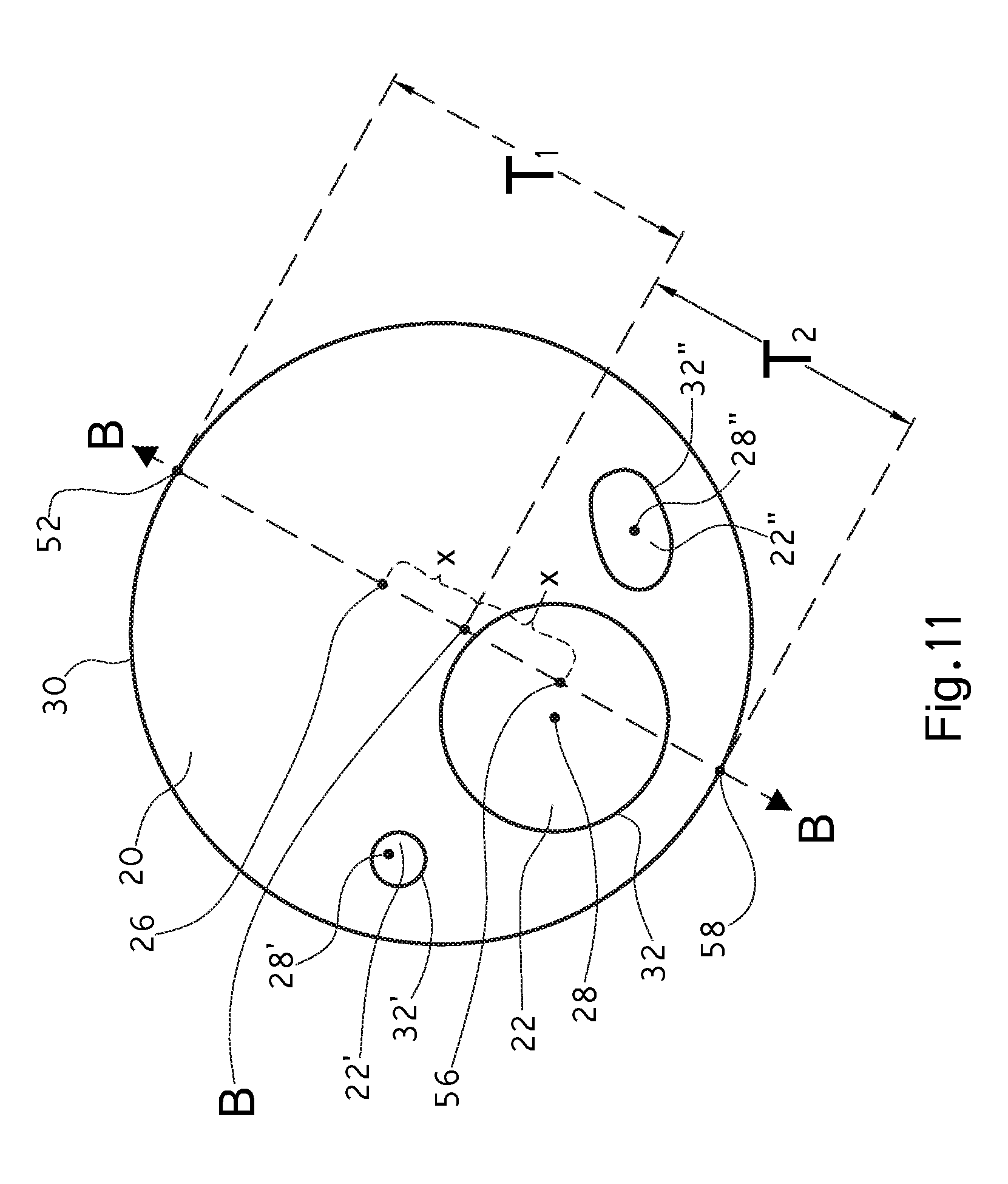
[0119] FIG. 11 shows a simplified view of an embodiment of a fiber, 10, herein. While the overall cross-sectional shapes are similar to that of FIG. 9, for the ease of calculation and understanding in this embodiment, the first component, 20, with a first cross-sectional shape, 30, surrounds three second components, 22, 22', and 22'', that are all identical in composition, molecular weight, etc. Each of the second components, 22, 22', and 22'', has its own respective second cross-sectional center of mass, 28, 28', and 28'' and own respective second cross-sectional shape, 32, 32', and 32''. Since these second components, 22, 22', and 22'', are identical in composition, we may easily find an aggregate center of mass, 56, mathematically.
[0120] Assuming for the sake of this embodiment that the first component has a lower shrinkage rate and is therefore on the outer edge of the helix (see FIG. 10 at 48), as measured from the center (see FIG. 10 at C) as compared to the second component, then an imaginary line B-B may be drawn connecting the first cross-sectional center of mass, 26 and the aggregate center of mass, 56. Point B is located on line B-B and is equidistant, x, from the first cross-sectional center of mass, 26 and the aggregate center of mass, 56. The imaginary line, B-B exits the first component, 20, at the first component edge, 52. For the purposes of this embodiment, the aggregated second component edge, 58, is effectively the point at which the line B-B exits the fiber, opposite of the first component edge, 52. Therefore first thickness, T.sub.1 is measured (or calculated) as the distance between point B and the first component edge, 52. The second thickness, T.sub.2 is measured (or calculated) as the distance between point B and the aggregated second component edge, 58. The respective lengths are therefore measured (or calculated) accordingly to calculate the shrinkage differential, .DELTA.S.
[0121] Without intending to be limited by theory, it is believed that the combination of different shrinkage rates and the eccentric cross-sectional centers of mass of the first component and the second component ensures that the fiber will crimp and form curls, typically resulting in a helix, when subjected to non-mechanical crimping such as heat, humidity, water, etc. as is appropriate. In an embodiment herein, the curling/crimping in this invention is driven exclusively by heat, specifically by heating the fiber to a temperature near or above the glass transition temperature, T.sub.g, of the component having the lower Tg, which allows the differential shrinkage in the components
[0122] The fiber; or staple fiber, herein may be formed by standard staple fiber processes, using standard bicomponent equipment known in the art.
[0123] In an embodiment herein, two or more thermoplastic polymers are extruded and brought into an eccentric cross-sectional relationship in a spinneret capillary. After exiting the spinneret capillary, the molten polymers are cooled (typically in a crossflow of chilled air), solidify and are stretched/drawn along the length of the fiber. These fibers are subsequently drawn further, by passing the fibers across a set of rollers and subsequently across another set of rollers running at a faster speed than the first set of rolls. Typically, heat is applied during this drawing phase to facilitate the orientation of polymer chains parallel to the long axis of the fiber.
[0124] In the typical prior art process, after drawing, it is typical to form crimps in the fibers in a stuffer-box crimping process. The stretched and crimped fibers may then be heated to dry off any water from the application of processing finishes, or to partially heat-set the fibers or pre-shrink them. The fibers are then cut to a length suitable for downstream processing such as carding and spun yarn formation.
[0125] In contrast, in the present invention the stuffer-box crimping step is bypassed, and in the last heating step, the fiber develops its curl from the shrinkage differential prior to cutting. It is also conceivable that the fiber could be cut prior to heating and then crimped/developing the curl.
[0126] Similarly, the continuous web or sliver herein may also be formed using standard continuous web or sliver processes, using standard equipment known in the art. Typically the first component is melted, typically simultaneously while the second component is melted. The first component is added to the second component either prior to, afterwards, or simultaneously during the extrusion of the first component and the second component through an extrusion die to form a fiber. As used herein, the term "extrusion", or "extruding" includes the melting of the polymers prior to forming the fiber cross section and pushing the molten fiber out of the spinneret capillary.
[0127] In the present invention, the term "sliver formation" indicates the step that occurs when the extruded, stretched, crimped or curled, and cut fiber has been carded and a card web/carded web is formed into a sliver.
[0128] The fiber is subjected to a drawing process which stretches out the fiber so as to align the polymer chains along the long axis of the fiber to form a drawn fiber. More specifically, the drawing process increases the ratio of polymer orientation in the direction of the (long) fiber axis and may also increase the crystallinity of the fiber by creating crystalline regions in the fiber interspersed with amorphous regions. Without intending to be limited by theory, it is believed that as the degree of drawing increases, the fiber contains an, increasing percentage of crystalline regions as compared to amorphous regions. Drawing may, for example, increase the molecular orientation of the fibers, change the appearance of the fibers, increase the tenacity of the fibers, increase the rigidity of the fibers, or change the feel and/or surface properties of the fibers. One skilled in the art understands that if crystallinity develops or increases, it can reduce overall fiber shrinkage and drawing also reduces fiber elongation, etc. The drawing processes useful herein include cold-drawing processes, partially-oriented yarn processes, hot-drawing processes, air-drawing processes and a combination thereof; or cold-drawing processes, hot-drawing processes and a combination thereof; or hot-drawing processes.
[0129] In an embodiment herein, the fiber, the multicomponent latent-crimping staple fiber, the staple fiber, etc. herein is drawn to an essentially maximum degree; or the maximum extent possible. In this context, the term "maximum" means that the fiber is drawn to the maximum draw ratio that the fiber can endure without breaking, minus a small margin of safety; or about a 30% margin of safety to about a 1% margin of safety; or about a 20% margin of safety to about a 1% margin of safety; or about a 10% margin of safety to about a 1% margin of safety. This maximum degree also is generally accompanied by a fiber elongation at break of less than or equal to about 50%; or from about 50% to about 0%; or less than or equal to about 45%; or from about 45% to about 0%; or less than or equal to about 35%; or from about 35% to about 0%. Without intending to be limited by theory, it is believed that in some embodiments simply stretching the fiber to a "maximum" draw ratio is not sufficient to optimize the fiber's strength; instead a combination of polymer orientation prior to drawing (set by fiber extrusion temperatures and speeds), drawing speeds and temperatures, the amount of draw distributed among two or more draw zones, and where heat is applied (e.g., on metal rolls, in a water bath between rolls, or in a steam chest between rolls, or combinations) may be required to develop the maximum practical strength in the fiber.
[0130] In an embodiment of the present invention, the process is optimized for the particular fiber's maximum tenacity via non-mechanical crimping; or heat-crimping, rather than via mechanical crimping. Without intending to be limited by theory, it is believed that such a process is not currently known or used in the art, as the prior processes may draw the fiber, but are not actually intended to maximize or otherwise optimize the tenacity. As noted in prior art processes, the curl is typically merely intended to bulk up the fiber.
[0131] In an embodiment herein, the drawing process is cold-drawing. In an embodiment herein the first component is a nylon and the drawing process is cold-drawing. In an embodiment herein, the first component is a nylon, the second component is a nylon, and the drawing process is cold-drawing. In an embodiment herein the drawing process is hot-drawing. In an embodiment herein the first component is a nylon and the drawing process is hot-drawing. In an embodiment herein, the first component is a nylon, the second component is a nylon, and the drawing process is hot-drawing. Without intending to be limited by theory, it is believed that certain high tenacity nylon fibers may benefit from hot-drawing so as to significantly increase the fiber's tenacity.
[0132] The drawn fiber herein is then typically non-mechanically crimped via subjecting the drawn fiber to an external condition such as heat, moisture, humidity, light, and a combination thereof; or heat, humidity and a combination hereof; or heat. to form a crimped fiber. As noted herein, the crimping process creates waves or curls in the drawn fiber such as the kinks found in natural fibers such as cotton and wool. However, one skilled in the art understands that natural fibers such as cotton and wool may have dramatically differing degrees of bending or curling along their length. In an embodiment herein, the crimping in the fibers of the present invention contain a "curl" that is a smooth and regular shape and is substantially the same at all points along the fiber. This allows the crimped fiber to be more easily spun into a yarn and/or further processed using standard equipment and processes.
[0133] Typically, the crimped fiber is then cut to form a staple fiber. Staple fibers herein are typically from about 3 mm to about 25 cm in length; or from about 18 mm to about 15 cm in length; or from about 2.54 cm to about 8 cm in length. The staple fibers may then be carded and then spun with a filament and/or with other staple fibers to form a yarn.
[0134] Traditionally, carding is a mechanical process where staple fibers are transported to the carding process in a bale, which may optionally first go through an "opener" or an "opening" process. The opened fibers then are carded on a carding machine or "card", which forms a web from the fibers. Other fibers may be introduced and blended prior to carding. With natural fibers, this carding process breaks up clumped up fibers and aligns individual fibers for subsequent processing. At the end of the carding process, the result is a sliver, a rope a tow, a yarn.
[0135] In an embodiment herein, cotton fibers are blended with the fiber; or staple fiber; or multicomponent latent-crimp staple fiber; or non-mechanically-crimped staple fiber; or drawn fiber; or crimped fiber of the invention, at the carding stage or subsequently in the yarn spinning process. Successful carding results in a fiber web in which the fibers hold together with each other such that the web does not collapse under its own weight or under gentle pulling, which is required to form the sliver. The flat card web is bunched together into a cylindrical "sliver," which is coiled into a can. The sliver is then further processed into a roving, which has better fiber orientation than the sliver, a narrower diameter and fewer fibers in the diameter than the sliver. The roving is spooled onto a spindle and then further spun into a yarn, which has a still narrower diameter, and fewer fibers in the diameter, but greater strength. The yarn may comprise staple fibers only, or it may be formed by wrapping staple fibers around a core filament yarn. During the yarn spinning process, other staple fibers may optionally be introduced and blended together.
[0136] It is recognized that the fiber; or staple fiber; or multicomponent latent-crimp staple fiber; or non-mechanically-crimped staple fiber; or drawn fiber; or crimped fiber, or continuous web; or sliver, herein may further contain an additive intended to modify one or more properties such as, for example, hydrophilicity, hydrophobicity, surface feel, color, infrared absorption, infrared reflection, florescence, UV absorption, UV reflection, tenacity, etc.
[0137] It is recognized that the additives that can help achieve these properties may be additives added to the fiber polymer(s) prior to or during extrusion, and/or components of fiber finishes added to the surface of the fiber, typically in the drawing stage prior to crimping/curling, or after crimping/curling and prior to cutting.
[0138] Accordingly, it is believed that it is now possible to use a low-cost, simple conventional staple fiber process and equipment to form a high-tenacity fiber; or staple fiber; or multicomponent latent-crimp staple fiber; or non-mechanically-crimped staple fiber; or drawn fiber; or crimped fiber, that can be successfully carded without blending with naturally- or mechanically-crimped fibers. Furthermore, the fiber; or staple fiber; or multicomponent latent-crimp staple fiber; or non-mechanically-crimped staple fiber; or drawn fiber; or crimped fiber, can also be carded and/or mixed with or into blends of other crimped fibers such as the micro-kinked nylon 6,6 staple fibers and others known in the art.
[0139] In an embodiment herein, the fiber; or staple fiber; or multicomponent latent-crimp staple fiber; or non-mechanically-crimped staple fiber; or drawn fiber; or crimped fiber, can also be carded and/or mixed with or into a natural fiber, a synthetic fiber, or a combination thereof; an animal fiber, a plant fiber, a synthetic fiber, or a combination thereof; or alpaca, angora, cashmere, cotton, lambswool, silk, wool, acetate, bamboo, lyocell, ramie, rayon, viscose, acrylic, a para-aramid polymer (e.g., Kevlar.TM.), a meta-aramid polymer (e.g., Nomex.TM.), nylon, polyester, spandex, rayon, and a, combination thereof; or cotton, silk, wool, acetate, rayon, acrylic, a para-aramid polymer (e.g., Kevlar.TM.), a meta-aramid polymer (e.g., Nomex.TM.), nylon, polyester, spandex, and a combination thereof; or cotton, silk, wool, rayon, a para-aramid polymer, a meta-aramid polymer, nylon, polyester, and a combination thereof.
[0140] In another embodiment, the fiber; or staple fiber; or multicomponent latent-crimp staple fiber; or non-mechanically-crimped staple fiber; or drawn fiber; or crimped fiber, or continuous web, herein may be further processed into for example a non-woven fabric, a sliver, a yarn, a knit fabric, and a woven fabric. These may then be further processed into a variety of products ranging from garments to carpeting, diapers, drapes, personal care items, industrial components, tires, linens, etc.
[0141] In an embodiment of the present invention, the increased fiber tenacity results in increased abrasion resistance for a woven fabric, such as a military garment or cloth, a protective garment or cloth, an emergency garment or cloth, or a workwear garment or cloth.
Example 1
[0142] "Type 420" high tenacity nylon 6,6 staple fibers available around the world from Invista (www.invista.com) are commonly accepted as having tenacities suitable for use in military apparel and workwear. This fiber's properties are described below in Table 1. This fiber has no measurable crimps per 2.54 cm and can be carded successfully only by blending it with mechanically- or naturally-crimped fibers, such as cotton. When only "Type 420" fibers are introduced into an industrial carding machine, the fibers load the card, preventing successful continuous formation of a fiber web that can be formed into a sliver for subsequent processing into yarn.
[0143] Fiber A is a drawn, high tenacity nylon 6,6 fiber made using high molecular weight nylon having a relative viscosity of 83. on a standard staple fiber extrusion line as described above. The tenacity at break and the tenacity at 7% elongation were measured after drawing and prior to crimping. Fiber A was then crimped using a standard stuffer-box mechanical crimper to crimp the fibers in a zig-zag crimp. The mechanically-crimped Fiber A was suitable for carding without blending with other crimped fibers, successfully forms a sliver, and is successfully subsequently processed into a yarn.
[0144] This fiber's properties are described below in Table 1.
[0145] Fiber B is a bicomponent nylon 6, 6, fiber produced in a side-by-side bowtie configuration as seen in FIG. 5. The first component is a nylon 6, 6 polymer with a relative viscosity of 83. The second component is a nylon 6, 6, polymer with a relative viscosity of 43. The tenacity at break and the tenacity at 7% elongation were measured. Fiber B was then run through a conventional staple drying oven to heat the fibers which heat crimped Fiber B into helixes having about 4 curls/cm (10 curls/2.54 cm). The heat-crimped Fiber B was suitable for carding without blending with other crimped fibers, successfully forms a sliver, and is successfully subsequently processed into a yarn.
[0146] The extrusion and drawing processes used to produce Fiber A, Fiber B, were optimized for high tenacity at break.
TABLE-US-00001 TABLE 1 Fiber A after Fiber A prior mechanical Fiber B prior Fiber B after Type 420 to crimping crimping to crimping heat crimping Tenacity @ 6.6 6.5 5.8 6.4 6.3 break (g/denier) Tenacity @ 7% 1.4 1.47 0.85 2.5 2.5 elongation (g/denier) Crimping 0 crimps 0 crimps 10 crimps 0 curls 10 curls degree (/2.54 cm)
[0147] As can be seen in Table 1, Fiber A possesses a significant lower tenacity according to either the tenacity at break test or the tenacity at 7% elongation test after being subjected to mechanical crimping. While Fiber A possessed similar tenacity at break and tenacity at 7% elongation as compared to Type 420 prior to mechanical crimping, the tenacities are significantly reduced after mechanical crimping. Therefore the Applicant believes that a similar reduction would occur to the Type 420 fibers if they were subjected to a normal mechanically-crimping process.
[0148] Fiber A's tenacity at break after mechanical crimping is only 89% of the tenacity prior to crimping. Fiber A's tenacity at 7% elongation after mechanical crimping is only 58% of the tenacity at 7% elongation prior to crimping.
[0149] In contrast, Fiber B shows that the tenacity at break after heat crimping is 98% of the tenacity at break prior to heat crimping. Fiber B also shows that the tenacity at 7% elongation after heat crimping is 100% (i.e., no loss of tenacity whatsoever) as compared to the tenacity at 7% elongation test before heat crimping.
[0150] Accordingly, the non-mechanical crimping employed in the production of Fiber B is significantly better at maintaining the tenacity at break and the tenacity at 7% elongation, as compared to mechanical crimping.
Example 2
[0151] Fiber C is as a 2.5 denier per filament, round homopolymer fiber made using polyphenylene sulfide with a melt index of 170. After drawing but before crimping, Fiber C's tenacity at break is 4.8 g/denier. After mechanical crimping, Fiber C's tenacity at break is 4.2 g/denier. This shows that Fiber C's tenacity at break is significantly reduced by the mechanical crimping.
[0152] Fiber D is a 2.5 denier per filament round eccentric sheath/core bicomponent fiber according to the invention herein, similar to that seen in FIG. 2, except that the polymer ratio is 50:50. The first component, forming the sheath, is a polyphenylene sulfide with a melt flow index of 170. The second component, forming the eccentric core, is a polyphenylene sulfide with a melt flow index of 100. After drawing, but before heat-crimping, Fiber D has a tenacity at break of 5.0 g/denier. After heat-crimping, Fiber D's tenacity at break is 4.8 g/denier. This shows that even after heat-crimping, Fiber D's tenacity at break was only slightly reduced and is still 96% of the tenacity at break prior to heat-crimping.
Example 3
[0153] A fiber of the present invention is made from two different nylons. The tenacity at break before crimping is 6 grams/denier and has a tenacity at 7% elongation of 1.4 grams per denier before crimping. Both the tenacity at break and tenacity at 7% elongation after non-mechanically crimping are 90 percent of the respective tenacity at break prior to crimping and tenacity at 7% elongation prior to crimping.
[0154] It should be understood that the above only illustrates and describes examples whereby the present invention may be carried out, and that modifications and/or alterations may be made thereto without departing from the spirit of the invention.
[0155] It should also be understood that certain features of the invention, which are, for clarity, described in the context of separate embodiments, may also be provided in combination in a single embodiment. Conversely, various features of the invention which are, for brevity, described in the context of a single embodiment, may also be provided separately, or in any suitable subcombination.
* * * * *
D00000
D00001
D00002
D00003
D00004
XML
uspto.report is an independent third-party trademark research tool that is not affiliated, endorsed, or sponsored by the United States Patent and Trademark Office (USPTO) or any other governmental organization. The information provided by uspto.report is based on publicly available data at the time of writing and is intended for informational purposes only.
While we strive to provide accurate and up-to-date information, we do not guarantee the accuracy, completeness, reliability, or suitability of the information displayed on this site. The use of this site is at your own risk. Any reliance you place on such information is therefore strictly at your own risk.
All official trademark data, including owner information, should be verified by visiting the official USPTO website at www.uspto.gov. This site is not intended to replace professional legal advice and should not be used as a substitute for consulting with a legal professional who is knowledgeable about trademark law.