Electrolyzer For Gaseous Carbon Dioxide
Li; Yuguang C. ; et al.
U.S. patent application number 16/132914 was filed with the patent office on 2019-05-02 for electrolyzer for gaseous carbon dioxide. The applicant listed for this patent is The Penn State Research Foundation. Invention is credited to Yuguang C. Li, Thomas E. Mallouk, Zhifei Yan.
| Application Number | 20190127865 16/132914 |
| Document ID | / |
| Family ID | 66245195 |
| Filed Date | 2019-05-02 |


View All Diagrams
| United States Patent Application | 20190127865 |
| Kind Code | A1 |
| Li; Yuguang C. ; et al. | May 2, 2019 |
ELECTROLYZER FOR GASEOUS CARBON DIOXIDE
Abstract
An electrochemical device and method can include techniques involving bipolar membrane electrolysis to transform an input product into an output product. Some embodiments can include a gas-diffusion electrode as a cathode, a bipolar membrane configured to facilitate autodissociation, and an anode that can be configured as a liquid-electrolyte style electrode or a gas-diffusion electrode. In some embodiments the electrochemical device can be configured as a CO.sub.2 electrolyzer that is designed to utilize input product including carbon dioxide gas and water to generate output products that can include gaseous carbon monoxide or other reduction products of carbon dioxide and gaseous oxygen or the oxidation products of a depolarizer such as hydrogen, methane, or methanol. Embodiments can be utilized in the production of fuels or feedstocks for fuels and carbon-containing chemicals, in air purification systems, flue gas treatment devices, and other machines and facilities.
| Inventors: | Li; Yuguang C.; (State College, PA) ; Yan; Zhifei; (State College, PA) ; Mallouk; Thomas E.; (State College, PA) | ||||||||||
| Applicant: |
|
||||||||||
|---|---|---|---|---|---|---|---|---|---|---|---|
| Family ID: | 66245195 | ||||||||||
| Appl. No.: | 16/132914 | ||||||||||
| Filed: | September 17, 2018 |
Related U.S. Patent Documents
| Application Number | Filing Date | Patent Number | ||
|---|---|---|---|---|
| 62577357 | Oct 26, 2017 | |||
| Current U.S. Class: | 1/1 |
| Current CPC Class: | C25B 1/00 20130101; C25B 9/08 20130101; C25B 9/10 20130101; C25B 13/08 20130101; C25B 3/04 20130101; C25B 1/10 20130101 |
| International Class: | C25B 9/10 20060101 C25B009/10; C25B 1/10 20060101 C25B001/10; C25B 3/04 20060101 C25B003/04; C25B 13/08 20060101 C25B013/08 |
Goverment Interests
STATEMENT REGARDING FEDERALLY SPONSORED RESEARCH AND DEVELOPMENT
[0002] This invention was made with government support under Grant No. DE-FG02-07ER15911 awarded by the Department of Energy. The Government has certain rights in the invention.
Claims
1. An electrochemical device, comprising: an electrochemical cell comprising a cathode, an anode, and a membrane; wherein: at least a portion of the cathode is separated from at least a portion of the anode by the membrane; the cathode comprises a gas-diffusion electrode; the anode comprises at least one of a liquid-electrolyte style electrode and a gas-diffusion electrode; and the membrane is a bipolar membrane, the bipolar membrane being configured to maintain a flux of protons to the cathode and also maintain a flux of hydroxide ions to the anode, wherein the electrochemical cell is configured to receive carbon dioxide gas and water and output reduction products of carbon dioxide at the cathode and oxygen or other oxidized products of a depolarizer at the anode.
2. The electrochemical device recited in claim 1, wherein the bipolar membrane comprises a cation exchange membrane and an anion exchange membrane.
3. The electrochemical device recited in claim 1, wherein the bipolar membrane is configured to promote autodissociation of water.
4. The electrochemical device recited in claim 1, wherein the bipolar membrane further comprises a membrane catalyst.
5. The electrochemical device recited in claim 4, wherein the membrane catalyst comprises at least one of a silicate, an amine polymer, graphite oxide, and an anolyte solution.
6. The electrochemical device recited in claim 2, wherein the anion exchange membrane comprises a cation-exchange polymer film.
7. The electrochemical device recited in recited in claim 1, wherein the electrochemical cell has a cell first end and a cell second end, the electrochemical device also comprising: a cathode flow medium positioned between the bipolar membrane and the cathode; and an anode flow medium positioned between the bipolar membrane and the anode.
8. The electrochemical device recited in claim 7, wherein: the cathode flow medium has at least one cell inlet and at least one cell outlet; and the anode flow medium has at least one cell inlet and at least one cell outlet.
9. The electrochemical device recited in claim 8, wherein the cathode flow medium comprises carbon and the anode flow medium comprises carbon.
10. The electrochemical device recited in claim 8, wherein: the electrochemical device is configured as a carbon dioxide electrolyzer, the cathode comprises a cathode catalysts configured as a carbon dioxide reduction catalyst; and the anode comprises an anode catalyst configured as a water oxidation catalyst or as a catalyst for oxidation of the depolarizer, the depolarizer comprising hydrogen, methane, or methanol.
11. The electrochemical device recited in claim 10, wherein the electrochemical cell is configured to receive carbon dioxide gas and generate reduction products of carbon dioxide that include any one or combination of formic acid, methanol, methane, formaldehyde, acetaldehyde, acetic acid, glyoxal, ethanol, ethene, ethane, ethylene glycol, dimethyl ether, methyl formate, propene, propane, n-propanol, isopropanol, and isomers of butanol, and hydrogen.
12. A method of reducing product crossover in an electrochemical cell of an electrochemical device, the method comprising: configuring a bipolar membrane of an electrochemical cell that is positioned between an anode and a cathode to cause ions to travel towards an anode electrode and a cathode electrode of the electrochemical cell when the electrochemical cell is under an applied current condition; operating the electrochemical cell so that the bipolar membrane facilitates a supply of protons (H.sup.+) to the cathode to cause water (H.sub.2O) to self-ionize via autodissociation to generate hydroxide ions (OH.sup.-) and protons H.sup.+ to supply a flux of the OH.sup.- to the anode and supply a flux of the H.sup.+ to the cathode.
13. The method recited in claim 12, wherein the flux of H.sup.+ provided by the bipolar membrane opposes product crossover in the electrochemical cell.
14. The method recited in claim 12, wherein the bipolar membrane has an anion exchange layer and a cation exchange layer joined together at an interfacial layer, the interfacial layer configured to catalyze autodissociation of H.sub.2O.
15. The method recited in claim 14, further comprising depositing at least one catalyst layer on the interfacial layer.
16. The method recited in claim 15, further comprising tuning water dissociation reactions at the interfacial layer via adjusting a type of the catalyst and/or an amount of the catalyst.
17. The method recited in claim 15, wherein the at least one catalyst layer comprises graphite oxide.
18. The method recited in claim 15, wherein the cation exchange layer and the anion exchange layer define a cation-anion exchange junction region; and wherein the cation-anion exchange junction is configured so that the cation exchange layer interpenetrates the anion exchange layer and/or the anion exchange layer interpenetrates the cation exchange layer.
19. The method recited in claim 18, further comprising: generating a plurality of transport pathways for water dissociation products H.sup.+ and OH.sup.- to flow via the interpenetrating cation exchange layer and anion exchange layer.
20. The method recited in claim 19, wherein: the electrochemical device is a carbon dioxide electrolyzer, the cathode comprises a cathode catalyst configured as a carbon dioxide reduction catalyst; the anode comprises an anode catalyst configured as a water oxidation catalyst or as a catalyst for a depolarizer, the depolarizer comprising hydrogen, methane, or methanol; and the electrochemical cell includes: a cathode flow medium between the cathode and the bipolar membrane, the cathode flow medium comprising carbon, at least one cell inlet of the cathode flow medium is configured to receive carbon dioxide, and at least one cell outlet of the cathode flow medium is configured to output carbon monoxide gas and/or water; an anode flow medium between the anode and the bipolar membrane, the anode flow medium comprising carbon, at least one cell inlet of the anode flow medium configured to receive water and/or an electrolyte and/or the depolarizer, and at least one cell outlet of the anode flow medium configured to output oxygen or the oxidized product of the depolarizer; and wherein the operating of the electrochemical cell comprises: feeding water and/or an electrolyte and/or the depolarizer to the anode flow medium; feeding a flow of carbon dioxide and water to the cathode flow medium; outputting oxygen and/or the oxidation products of the depolarizer from the anode flow medium; and outputting carbon monoxide and/or other reduction products of carbon dioxide from the cathode flow medium.
Description
CROSS-REFERENCE TO RELATED APPLICATIONS
[0001] This patent application is related to and claims the benefit of priority of U.S. Provisional Patent Application Ser. No. 62/577,357 filed on Oct. 26, 2017, the entire contents of which is incorporated herein by reference.
FIELD OF THE INVENTION
[0003] Embodiments can relate to an electrochemical device capable of gas phase electrolysis and bipolar membrane electrolysis.
BACKGROUND OF THE INVENTION
[0004] Conventional electrochemical reduction of carbon dioxide systems and methods can be appreciated from U.S. Pat. No. 9,481,939, U.S. Pat. No. 9,181,625, U.S. Pat. No. 9,085,827, U.S. Pat. Publ. No. 2017/0183789, U.S. Pat. Publ. No. 2013/0118911, and Pat. Publ. No. CN 102912374. Conventional systems may be inefficient, have poor stability, and/or have difficulty in separating reaction products from the electrolytes. These and other disadvantages may limit the use of conventional electrochemical reduction systems.
BRIEF SUMMARY OF THE INVENTION
[0005] Embodiments can be related to an electrochemical device that may include techniques involving gas phase electrolysis and bipolar membrane electrolysis to transform an input product into an output product. Some embodiments can include an electrochemical device having at least one electrochemical cell, each electrochemical cell having a cathode, a membrane, and an anode. In some embodiments, input product can be introduced into the electrochemical device at the cathode. This can include introducing an input product in a gas phase. Reactions at the cathode can transform the input product into reduced chemical products. Some of these reduced chemical products can be caused to exit the electrochemical device as output product. Some of these reduced chemical products can be caused to react with the membrane to generate additional chemical products. The additional chemical products can be caused to react with the anode. This can generate additional output product.
[0006] As a non-limiting example, carbon dioxide gas and water may be introduced into the electrochemical device at the cathode. Reactions at the cathode can transform the carbon dioxide gas into reduction products of carbon dioxide and oxygen as output products. The reduction products of carbon dioxide and the oxygen may be directed out from the electrochemical device. In some embodiments, water can be introduced into the electrochemical device at the anode. Liquid electrolyte and/or the anode can electrochemically drive the oxidation of the water to oxygen as an output product. The oxygen can then be directed out from the electrochemical device. In some embodiments, a depolarizer such as methane, hydrogen, or methanol can be introduced to the anode of the cell and its oxidation products may be directed out from the electrochemical device. Some embodiments can include a gas-diffusion anode. This may be used to generate an electrochemical device without a liquid electrolyte.
[0007] With some embodiments, introduction of input product as a gas can allow for reaction products to be generated in the gas phase. This may also allow for collection of output product in the gas phase. These gas phase products can eliminate the need to provide product separation techniques, as no product is being dissolved in a liquid electrolyte solution. As no reactant is being dissolved in a liquid electrolyte solution, the reactants are not caused to transport through a liquid, which can improve upon the transport rate of chemical species within the electrochemical device.
[0008] Some embodiments can include use of a bipolar membrane. Embodiments of the bipolar membrane can be used to separate the cathode and the anode, as well as isolate the reactants associated with the cathode and isolate the reactants associated with the anode. Embodiments of the bipolar membrane can also be configured to manage flux of chemical species from the bipolar membrane to the cathode and/or to the anode. For example, the bipolar membrane can be used to provide a flux of protons to the cathode and a flux of hydroxide ions to the anode. This may generate an electrochemical device that can eliminate or reduce undesired crossover of chemical product between the cathode and anode. This can also allow the electrochemical device to operate with a stable electrolyte pH, even under long-term operation.
[0009] While various embodiments may describe an electrochemical device configured for carbon dioxide electrolysis into carbon monoxide and oxygen, other forms of output product can be generated. For example, it is contemplated for embodiments of the electrochemical device to be used for carbon dioxide electrolysis into syngas (carbon monoxide+hydrogen) and oxygen. Syngas can be used as a precursor to hydrocarbon fuels, other fuels, and other high value chemicals (e.g., propane, gasoline, methanol, dlmethylether (DME), formate, methane, methanol, ethylene glycol, butanol, etc. It is also contemplated for embodiments of the electrochemical device that different cathode catalysts may be chosen to reduce carbon dioxide directly to other carbon-containing products, such as formic acid, acetic acid, ethylene, propylene, methanol, ethanol, propanol and ethylene glycol.
[0010] In one embodiment, an electrochemical device can include an electrochemical cell comprising a cathode, an anode, and a membrane. At least a portion of the cathode can be separated from at least a portion of the anode by the membrane. The cathode can have a gas-diffusion electrode. The anode can have at least one of a liquid-electrolyte style electrode and a gas-diffusion electrode. The membrane can be a bipolar membrane. The bipolar membrane can be configured to maintain a flux of protons to the cathode and also maintain a flux of hydroxide ions to the anode. The electrochemical cell can be configured to receive carbon dioxide gas and water and output reduction products of carbon dioxide and oxygen.
[0011] In some embodiments, the bipolar membrane can include a cation exchange membrane and an anion exchange membrane. In some embodiments, the bipolar membrane can be configured to promote autodissociation. In some embodiments, the bipolar membrane further can have a membrane catalyst. In some embodiments, the membrane catalyst can be at least one of a silicate, an amine polymer, a graphite oxide, and an anolyte solution. In some embodiments, the anion exchange membrane can be laminated by a cation-exchange polymer film. In some embodiments, the cation-exchange polymer film can be a sulfonated tetrafluoroethylene based fluoropolymer-copolymer. In some embodiments, the cation-exchange polymer film can be a sulfonated poly(ether ether ketone) polymer. In some embodiments, the cation-exchange polymer film can be a polymeric weak acid, such as poly(acrylic acid). In some embodiments, the cation-exchange film can contain an inorganic cation exchanger such as a clay, a layered transition metal oxide, or graphite oxide, either alone or as a polymer composite. In some embodiments, a surface of the cation exchange membrane can be patterned and/or a surface of the anion exchange membrane can be patterned. In some embodiments, the cathode can be a cathode catalyst. In some embodiments, the cathode catalyst can be gold, silver, copper, indium, bismuth, lead, tin, tellurium, and/or germanium. In some embodiments, the cathode catalyst can be mixed with a binder, a polymeric electrolyte coating, and/or an ionic liquid. In some embodiments, the anode can be an anode catalyst. In some embodiments, the anode catalyst can be at least one of iridium oxide, ruthenium alloys, mixed oxides of ruthenium containing iridium and/or platinum, mixed metal oxides containing cobalt, nickel, iron, manganese, lanthanum, cerium, copper, nickel borate, cobalt phosphate, NiFeOx.
[0012] In one embodiment, an electrochemical device can include an electrochemical cell having a cell first end and a cell second end. The electrochemical device can have a cathode with a gas-diffusion electrode. The electrochemical device can have an anode with at least one of a liquid-electrolyte style electrode and a gas-diffusion electrode. The electrochemical device can have bipolar membrane separating at least a portion of the cathode from at least a portion of the anode. The electrochemical device can have a cathode flow medium comprising carbon. The electrochemical device can have an anode flow medium comprising carbon. The electrochemical device can have a frame configured to hold the cathode flow medium, the cathode, the bipolar membrane, the anode, and the anode flow medium together.
[0013] In some embodiments, at least one of the cathode flow mediums and the anode flow medium has at least one of a cell inlet and a cell outlet. In some embodiments, the frame has at least one pass-through region corresponding with at least one of the cell inlets and the cell outlet. In some embodiments, the frame seals the electrochemical cell except at the at least one pass-through region. In some embodiments, the cathode has a cathode catalyst configured as a reduction catalyst. In some embodiments, the anode has an anode catalyst configured as an oxidation catalyst.
[0014] In one embodiment, a carbon dioxide electrolyzer can include an electrochemical cell comprising a cathode, an anode, and a membrane. At least a portion of the cathode can be separated from at least a portion of the anode by the membrane. The cathode can have a gas-diffusion electrode. The anode can have at least one of a liquid-electrolyte style electrode and a gas-diffusion electrode. The membrane can be a bipolar membrane. The cathode can be a cathode catalyst configured as a carbon dioxide reduction catalyst. The anode can be an anode catalyst configured as a water oxidation catalyst.
[0015] In one embodiment, an electrochemical device can include an electrochemical cell having a cell first end and a cell second end. The electrochemical device can have a cathode comprising a gas-diffusion electrode. The electrochemical device can have an anode comprising at least one of a liquid-electrolyte style electrode and a gas-diffusion electrode. The electrochemical device can have a bipolar membrane separating at least a portion of the cathode from at least a portion of the anode. The electrochemical device can have a cathode flow medium comprising carbon. In some embodiments, the cathode flow medium can be located between the cell first end and the cathode. In some embodiments, at least one cell inlet can be formed in the cathode flow medium configured to receive carbon dioxide gas. In some embodiments, at least one cell outlet can be formed in the cathode flow medium configured to output carbon monoxide gas and/or water. In some embodiments, the device can have an anode flow medium comprising carbon. The anode flow medium can be located between the cell second end and the anode. At least one cell inlet can be formed in the anode flow medium configured to receive water and/or electrolyte. At least one cell outlet can be formed in the anode flow medium configured to output oxygen. The bipolar membrane can be configured to maintain a flux of protons to the cathode and a flux of hydroxide ions to the anode.
[0016] In one embodiment, a method of reducing product crossover in an electrochemical cell can involve configuring a bipolar membrane of an electrochemical to cause ions to travel towards an anode electrode and a cathode electrode of the electrochemical cell when the electrochemical cell is under an applied current condition.
[0017] In some embodiments, the method can involve the bipolar membrane being configured to supply protons (H.sup.+) to the cathode and to cause water (H.sub.2O) to self-ionize via autodissociation to generate hydroxide ions (OH.sup.-). In some embodiments, the method can involve the bipolar membrane being configured to supply the OH.sup.- to the anode. In some embodiments, the method can involve generating a reverse bias to provide a flux of H.sup.+ to the cathode. In some embodiments, the method can involve the flux of H.sup.+ opposing the direction of product crossover in the electrochemical cell. In some embodiments, the method can involve configuring the bipolar membrane to have an anion exchange layer and a cation exchange layer joined together at an interfacial layer, the interfacial layer configured to catalyze the autodissociation of H.sub.2O. In some embodiments, the method can involve depositing at least one catalyst layer on the interfacial layer. In some embodiments, the method can involve tuning the water dissociation reaction at the interfacial layer via adjusting a type of the catalyst and/or an amount of the catalyst.
[0018] In one embodiment, a bipolar membrane can include a cation exchange layer and an anion exchange layer, the cation exchange layer being adjacent the anion exchange layer to form a cation-anion exchange junction region. The bipolar membrane can include at least one catalyst layer formed within the cation-anion exchange junction region. In some embodiments, at least one catalyst layer can be configured to decrease the electric field intensity applied across the cation-anion exchange junction region. In some embodiments, at least one catalyst layer is graphite oxide.
[0019] In at least one embodiment, a bipolar membrane can include a cation exchange layer and an anion exchange layer, the cation exchange layer being adjacent the anion exchange layer to form a cation-anion exchange junction region. In some embodiments, the cation-anion exchange junction can be configured so that the cation exchange layer interpenetrates the anion exchange layer and/or the anion exchange layer interpenetrates the cation exchange layer. In some embodiments, the interpenetrating cation exchange layer and anion exchange layer can generate a plurality of transport pathways for water dissociation products H.sup.+ and OH.sup.- to flow.
[0020] A method of reducing product crossover in an electrochemical cell of an electrochemical device can include various steps. These steps can include, for example, configuring a bipolar membrane of an electrochemical cell that is positioned between an anode and a cathode to cause ions to travel towards an anode electrode and a cathode electrode of the electrochemical cell when the electrochemical cell is under an applied current condition and operating the electrochemical cell so that the bipolar membrane facilitates a supply of protons (H.sup.+) to the cathode, to cause water (H.sub.2O) to self-ionize via autodissociation to generate hydroxide ions (OH.sup.-) and protons H.sup.+ to supply a flux of the OH.sup.- to the anode and supply a flux of the H.sup.+ to the cathode.
[0021] In some embodiments of the method of reducing product crossover in the electrochemical cell of an electrochemical device, the electrochemical device can be a carbon dioxide electrolyzer, the cathode can include a cathode catalyst configured as a carbon dioxide reduction catalyst, the anode can include an anode catalyst configured as a water oxidation catalyst, and the electrochemical cell can include: (i) a cathode flow medium between the cathode and the bipolar membrane and there is at least one cell inlet of the cathode flow medium configured to receive carbon dioxide and at least one cell outlet of the cathode flow medium configured to output carbon monoxide gas and/or water; and (ii) an anode flow medium between the anode and the bipolar membrane, at least one cell inlet of the anode flow medium is configured to receive water and/or an electrolyte, and at least one cell outlet of the anode flow medium is configured to output oxygen. For such embodiments, the operating of the electrochemical cell can include: feeding water and/or an electrolyte to the anode flow medium; feeding a flow of carbon dioxide to the cathode flow medium; outputting gaseous oxygen from the anode flow medium; and outputting carbon monoxide and/or water from the cathode flow medium.
[0022] Further features, aspects, objects, advantages, and possible applications of the present invention will become apparent from a study of the exemplary embodiments and examples described below, in combination with the Figures, and the appended claims.
BRIEF DESCRIPTION OF THE FIGURES
[0023] The above and other objects, aspects, features, advantages and possible applications of the present invention will be more apparent from the following more particular description thereof, presented in conjunction with the following drawings, in which:
[0024] FIG. 1 shows a first exemplary embodiment of an electrochemical device.
[0025] FIG. 2 shows an exploded view of the first exemplary embodiment of an electrochemical device.
[0026] FIG. 3 shows an embodiment of an electrochemical cell that may be used in the first exemplary embodiment of an electrochemical device.
[0027] FIG. 4 shows a cut-away view of the first exemplary embodiment of an electrochemical device.
[0028] FIG. 5 is another view of the first exemplary embodiment of an electrochemical device.
[0029] FIG. 6 is a graph shows stability data for an embodiment of an electrochemical device.
[0030] FIG. 7 is a graph comparing cell potential over time for an embodiment of the electrochemical device and a conventional electrochemical device using a nafion cation exchange membrane.
[0031] FIG. 8 is a graph showing a current-voltage curve for an embodiment of the electrochemical device operating at high current density.
[0032] FIGS. 9 and 10 each shows a faradaic efficiency plot for a conventional device having a bipolar membrane electrolyzer with an aqueous bicarbonate catholyte. These graphs demonstrate examples of degradation of electrode selectivity that often occurs in conventional devices.
[0033] FIG. 11 shows a current density plot of a conventional bipolar membrane compared to an embodiment of a bipolar membrane that may be used with an embodiment of the electrochemical device.
[0034] FIG. 12 is an exemplary block diagram showing the transport of methanol by electroosmosis through a conventional anion-exchange membrane.
[0035] FIG. 13 is an exemplary block diagram showing outward flux of H.sup.+ and OH.sup.- that can occur in an embodiment of a bipolar membrane.
[0036] FIG. 14 is graphs showing crossover of formate, methanol, and ethanol versus time in exemplary electrochemical cells having an anion exchange membrane and an embodiment of the bipolar membrane.
[0037] FIG. 15 shows graphs illustrating crossover of formate and methanol at different applied currents after 2 hours in exemplary electrochemical cells having an anion exchange membrane and an embodiment of the bipolar membrane.
[0038] FIG. 16 shows graphs illustrating crossover of formate and methanol at zero current density with 0.5 M KHCO.sub.3 used as electrolyte on both the cathode and anode sides of exemplary electrochemical cells having an anion exchange membrane and an embodiment of the bipolar membrane.
[0039] FIG. 17 shows a schematic of the preparation of an embodiment of the bipolar membrane having an exemplary interfacial catalyst layer and a scanning electron microscope (SEM) image of the bipolar membrane.
[0040] FIG. 18 is a plot showing J-E curves of embodiments of the bipolar membrane having an exemplary interfacial catalyst layer prepared by an exemplary layer-by-layer technique.
[0041] FIG. 19 is a plot showing the water dissociation rate constant kd measured for embodiments of the bipolar membrane having an exemplary interfacial catalyst layer.
[0042] FIG. 20 is a plot showing water dissociation reaction resistance Rw measured for embodiments of the bipolar membrane having an exemplary interfacial catalyst layer.
[0043] FIG. 21 is a plot showing depletion region thickness as a function of reverse bias voltage for embodiments of the bipolar membrane having an exemplary interfacial catalyst layer.
[0044] FIG. 22 is a graph showing J-E curves for embodiments of the bipolar membrane having an exemplary interfacial catalyst layer.
[0045] FIG. 23 is a graph showing potential distribution profiles for embodiments of the bipolar membrane having an exemplary interfacial catalyst layer.
[0046] FIG. 24 is a graph showing concentration profiles of the water dissociation products H.sup.+ and OH.sup.- for embodiments of the bipolar membrane having an exemplary interfacial catalyst layer.
[0047] FIG. 25 is a graph showing electrolyte KNO.sub.3 ion distributions for embodiments of the bipolar membrane having an exemplary interfacial catalyst layer.
[0048] FIG. 26 shows schematic drawings of the depletion region for embodiments of the bipolar membrane having an exemplary interfacial catalyst layer and embodiments without an exemplary interfacial catalyst layer, along with enlarged views of the cation-anion exchange junction for each. The thickness of the black arrows indicate the higher electric field in the bipolar membrane without the exemplary interfacial catalyst layer.
[0049] FIG. 27 shows a graph of electric field intensity at a cation-anion exchange junction for embodiments of the bipolar membrane having an exemplary interfacial catalyst layer and embodiments without an exemplary interfacial catalyst layer.
[0050] FIG. 28 shows a graph of electric field intensity at cation-anion exchange junction for embodiments of the bipolar membrane having an exemplary interfacial catalyst layer and embodiments without an exemplary interfacial catalyst layer.
[0051] FIG. 29 shows a scanning electron microscope image and a schematic of a cation-anion exchange junction of an embodiment of a 3D bipolar membrane with intertwined anion exchange layer-cation exchange layer fibers.
[0052] FIG. 30 is a graph showing J-E curves for a cation-anion exchange junction of an embodiment of a 3D bipolar membrane.
[0053] FIG. 31 is a graph showing the water dissociation rate constant kd for a cation-anion exchange junction of an embodiment of a 3D bipolar membrane.
[0054] FIG. 32 is a graph showing the water dissociation reaction resistance Rw for a cation-anion exchange junction of an embodiment of a 3D bipolar membrane.
[0055] FIG. 33 is a graph showing depletion region thickness d as a function of reverse bias voltage for a cation-anion exchange junction of an embodiment of a 3D bipolar membrane.
[0056] FIG. 34 is a graph showing J-E curves for embodiment of a bipolar membrane.
[0057] FIG. 35 is a graph showing steady-state performance of embodiment of a bipolar membrane.
DETAILED DESCRIPTION OF THE INVENTION
[0058] The following description is of an embodiment presently contemplated for carrying out the present invention. This description is not to be taken in a limiting sense, but is made merely for the purpose of describing the general principles and features of the present invention. The scope of the present invention should be determined with reference to the claims.
[0059] Referring to FIGS. 1-4, various embodiments of the apparatus disclosed herein can include an electrochemical device 10 capable of gas phase electrolysis and bipolar membrane electrolysis. Embodiments of the electrochemical device 10 can be configured to generate an output product from an input product. The input product can be a gas, a liquid, a solid or combinations thereof e.g. a slurry, gas having solid particulates entrained therein, a liquid having solid particles entrained therein, etc.). The output product can be a gas, a liquid, a solid, or a combination thereof (e.g. a slurry, a gas having solid particulates entrained therein, etc.). In some embodiments, both the input product and the output product include a gas. In some embodiments, the output product can be a reduced chemical product of the input product, an oxidized product of the input product, and/or a combination of both.
[0060] Some embodiments of the electrochemical device 10 can be configured as an electrolyzer. For example, embodiments of the electrochemical device 10 can be configured to use electric current to drive chemical reactions that may facilitate generating the output product from the input product. In some embodiments, the electrochemical device 10 can be configured as a carbon dioxide (CO.sub.2) electrolyzer. As a non-limiting example, the electrochemical device 10 can be configured to receive carbon dioxide (CO.sub.2) gas as an input product at the cathode 14. Reactions within the electrochemical device 10 can generate carbon monoxide (CO), water (H.sub.2O), and/or hydrogen (H.sub.2) as an output product. The CO, the H.sub.2O, and/or the H.sub.2 may be caused to exit the electrochemical device 10 for capture or further processing. In some embodiments, the H.sub.2O can be caused to self-ionize at the membrane 22 via autodissociation to generate protons (H.sup.+) and hydroxide ions (OH.sup.-). Some of the H.sub.2O generated at the cathode 14 can be caused to move to the anode 18. Additional H.sub.2O can be introduced into the electrochemical device 10 as input product at the anode 18. The additional H.sub.2O can be in the form of a liquid or a vapor. If the additional H.sub.2O is in the form of a liquid, the OH.sup.- may be used to react with the anode 18 via electrolyte of the electrochemical device 10 to generate oxygen (O.sub.2) and/or H.sub.2O as additional output product. If the additional H.sub.2O is in the form of a vapor, the OH.sup.- may be used to react directly with the anode 18 of electrochemical device 10 to generate oxygen (O.sub.2) and/or H.sub.2O as additional output product. The O.sub.2 and/or the H.sub.2O may be caused to exit the electrochemical device 10 for capture or further processing.
[0061] As explained herein, other input products can be used, such as humidified CO.sub.2 gas, for example. The input product can also be a mixture of gases that may include gases other than CO.sub.2 gas. In addition, other output products can be generated, such as formic acid, formate, methane, methanol, ethylene, ethylene glycol, butanol, etc. For example, in the situation in which the device 10 is used for CO.sub.2 reduction to CO, the device 10 can be configured to receive CO.sub.2 gas as an input and generate CO.sub.2 and O.sub.2. In the situation in which the device 10 is used for CO.sub.2 reduction to products other than CO (e.g., formate, methanol, ethylene, etc.), the device 10 can be configured to receive CO.sub.2 gas and H.sub.2O as inputs and generate reduction products of and CO.sub.2 and O.sub.2. The reduction products of CO.sub.2 can include but are not limited to formic acid, methanol, methane, formaldehyde, acetaldehyde, acetic acid, glyoxal, ethanol, ethene, ethane, ethylene glycol, dimethyl ether, methyl formate, propene, propane, n-propanol, isopropanol, isomers of butanol, as well as mixtures of these products and hydrogen.
[0062] Some embodiments of the electrochemical device 10 can include an electrochemical cell 12 structure. Embodiments of the electrochemical cell 12 structure can include a cathode 14 within a cathode flow medium 16 and an anode 18 within an anode flow medium 20. The cathode flow medium 16 and/or cathode 14 can be separated from the anode flow medium 20 and/or anode 18 by a membrane 22. The electrochemical cell 12 can be configured to facilitate intake of an input product. The input product can enter the electrochemical cell 12 at a cell inlet 26. The electrochemical cell 12 can be configured to generate an output product from the input product. The electrochemical cell 12 can be configured to transform the input product at the cathode 14 via a reduction reaction. The electrochemical cell 12 can be configured to transform the input product at the anode 18 via an oxidation reaction. The output product can exit the electrochemical cell 12 at a cell outlet 28.
[0063] The electrochemical cell 12 may include a cathode 14. The cathode 14 may be positioned adjacent or within the cathode flow medium 16. The cathode flow medium 16 can be positioned at a cell first end 30 of the electrochemical cell 12. The electrochemical cell 12 can include an anode 18. The anode 18 may be positioned adjacent or within the anode flow medium 20. The anode flow medium 20 can be positioned at a cell second end 32 of the electrochemical cell 12. The electrochemical cell 12 can include a membrane 22. The membrane 22 may be disposed between the cell first end 30 and the cell second end 32. This can include being disposed between the cathode 14 and the anode 18. A volume of space between the cathode 14 and the cell first end 30 of the electrochemical cell 12 can be referred to as a cathode flow medium 16. The cathode flow medium 16 can include a carbon material filled within the volume of space between the cathode 14 and the cell first end 30 of the electrochemical cell. A volume of space between the anode 18 and the cell second end 32 can be referred to as an anode flow medium 20. The anode flow medium 20 can include a carbon material or a graphite oxide material filled within the volume of space between the anode 18 and the cell second end 32. In some embodiments, the membrane 22 can separate at least a portion of the cathode 14 from at least a portion of the anode 18. This can include a physical separation, a chemical separation (e.g., chemical isolation), an electrical separation (e.g., electrical isolation), etc.
[0064] The electrochemical cell 12 can include any number of cathodes 14, anodes 18, and/or membranes 22. For example, the electrochemical cell 12 can include a single cathode 14 or a plurality of cathodes 14. With a plurality of cathodes 14, each cathode 14 may be stacked against each other in a serial formation, in a staggered formation, or in any other type of formation. The electrochemical cell 12 can include a single anode 18 or a plurality of anodes 18. With a plurality of anodes 18, each anode 18 may be stacked against each other in a serial formation, in a staggered formation, or in any other type of formation. The membrane 22 can include a single membrane 22 or a plurality of membranes 22. With a plurality of membranes 22, each membrane 22 may be stacked against each other in a serial formation, in a staggered formation, or in any other type of formation. The electrochemical cells 12 may also be stacked in series to create a multi-cell electrolyzer.
[0065] The cathode flow medium 16 can be configured as a flow compartment. This can include allowing flow of input product and/or output product. The cathode flow medium 16 can include a cell inlet 26 to allow for introduction of input product. The cathode flow medium 16 can include a cell outlet 28 to allow for removal of output product. The anode flow medium 20 can be configured as a flow compartment. This can include allowing flow of input product, electrolyte, and/or output product. The anode flow medium 20 can include a cell inlet 26 to allow for introduction of input product and/or electrolyte. The anode flow medium 20 can include a cell outlet 28 to allow for removal of electrolyte and/or output product.
[0066] Any one or both of the cathode flow medium 16 and/or anode flow medium 20 can include a desired shape or path. For example, a portion of the cathode flow medium 16 can have a pathway 24 formed into a portion thereof or onto a surface thereof. A portion the anode flow medium 20 can have a pathway 24 formed into a portion thereof or onto a surface thereof. The pathway 24 can facilitate flow of fluid (e.g., input product, output product, electrolyte, etc.) through the electrochemical cell 12. In some embodiments, the pathway 24 can be configured to maximize the amount of contact the fluid has with an electrode of the electrochemical cell 12. For example, the cathode flow medium 16 can include a pathway 24 at an interface between the cathode flow medium 16 and the cathode 14. The pathway 24 can direct flow of the input product and/or output product to maximize the amount to contact (e.g., surface area, time, etc.) the input product and/or output product has with a surface of the cathode 16 while the input product and/or output product is within the electrochemical cell 12. The anode flow medium 20 can include a pathway 24 at an interface between the anode flow medium 20 and the anode 18. The pathway 24 can direct flow of the input product, output product, and/or electrolyte to maximize the amount to contact (e.g., surface area, time, etc.) the input product, output product, and/or electrolyte has with a surface of the anode 18 while the input product, the output product, and/or electrolyte is within the electrochemical cell 12. In addition, or in the alternative, the pathway 24 can be configured to minimize the amount of contact or provide another predetermined amount of contact of fluid with an electrode of the system.
[0067] The pathway 24 can be straight, serpentine, zigzagged, spiraled, etc. The shape and size of any pathway 24 can be the same as or different from another pathway 24. The number, shape, dimension, and size of any pathway 24 of the cathode flow medium 16 can be the same as or different from the number, shape, dimension, and size of any pathway 24 of the anode flow medium 20. The shape, size, dimension, and path direction can be used to influence kinetics, fluid dynamics, etc. In some embodiments, any of the pathways 24 can be in fluid communication with any one of the cell inlets 26 and/or cell outlets 28.
[0068] The cathode 14 can include an electrical contact 34 configured to transport electrical charge. The anode 18 can include an electrical contact 34 configured to transport electrical charge. In some embodiments, the electrical contact 34 of the cathode 14 and the electrical contact 34 of the anode 18 can be placed into electrical connection with a load 36 for transmission of electrical current.
[0069] The electrochemical device 10 can be operated in a galvanostatic mode, in which the anode 18 can be maintained at a constant current. The electrochemical device 10 can be operated in a potentiostatic mode, in which the potential difference between the cathode 14 and the anode 18 can be held constant. For example, the product selectivity can exhibit a voltage dependence behavior (e.g., at different voltages, the ratio of products is different). This can be used as a control parameter since the required ratio of hydrogen and carbon monoxide (for a CO.sub.2 gas input) is different for different subsequent reactions. Thus, one can control the ratio of the products by simply controlling the voltage of the reaction in potentiostatic mode. This may be suitable for applications where a dynamic response is required. For galvanostatic mode, a constant flow rate of the products can be generated. This may be more suitable for a stationary system (e.g., where one single desired mix of products may be required for larger scale operation).
[0070] In some embodiments, the electrochemical device 10 can include a frame 38. The frame 38 can be a structure that holds the electrochemical cell 12 together and/or seals the electrochemical cell 12. Sealing can include forming a fluid (e.g., gas and/or liquid) seal so as to prevent any fluid from entering and/or exiting the electrochemical cell 12 except at a selected pass-through region 40. For example, the frame 38 can be structured so that is generates a fluid seal around the electrochemical cell 12, but includes a non-sealed portion to allow fluid to pass there-through. The non-sealed portion can be the pass-through region 40. The pass-through region 40 can be an opening in the frame 38, a permeable portion of the frame 38, a semi-permeable portion of the frame 38, etc. The frame 38 can be made from metal, polymer, rubber, etc. The frame 38 can also have any of a number of different shapes and sizes (e.g. cubical in shape, disc in shape, polygonal in shape, elliptical in shape, etc.) to meet a particular set of design criteria. The frame 38 can be configured so that the electrochemical cell 12 can be incorporated into a machine, a facility, or other type of device (e.g. conduit of an electricity generation plant, conduit of an exhaust conduit for an engine, incorporated into a gas turbine arrangement, incorporation into a flue gas treatment apparatus, incorporation into a heating, ventilation, and air conditioning (HVAC) system of a building, inclusion into an air purification system of a vehicle, etc.).
[0071] In at least one embodiment, the electrochemical device 10 can include an electrochemical cell 12 having a frame 38 that holds the electrochemical cell 12 together. For example, the frame 38 can be a structure that holds the cathode 14, the membrane 22, and the anode 18 of the electrochemical cell 12 in a serial configuration. The electrochemical device 10 can have a plurality of sides. For example, the electrochemical device 10 may have a cubic structure with a device first side 42a, a device second side 42b, a device third side 42c, a device fourth side 42d, a device fifth side 42e, and a device sixth side 42f The electrochemical cell 12 can be configured such that the cell first end 30 is adjacent the device first side 42a. The cell second end 32 can be adjacent the device second side 42b. The device third side 42c can be the top. The device fourth side 42d can be the bottom. The device fifth side 42e can be the front. The device sixth side 42f can be the rear. While the various embodiment describe and illustrate the device 10 as having a cubic structure, other shapes and number of sides can be used to form the device 10.
[0072] The frame 38 can form a seal around the electrochemical device 10 except for at a pass-through region 40. For example, a first pass-through region 40 can be formed into the frame 38 to facilitate introduction of input product into the electrochemical cell 12. This can include facilitating introduction of input product to a cell inlet 26 of the cathode flow medium 16. A second pass-through region 40 can be formed into the frame 38 to facilitate removal of output product from the electrochemical cell 12. This can include facilitating removal of output product from a cell outlet 28 of the cathode flow medium 16.
[0073] A third pass-through region 40 can be formed into the frame 38 to facilitate introduction of electrolyte into the electrochemical cell 12. This can include facilitating introduction of electrolyte to a cell inlet 26 of the anode flow medium 20. A fourth pass-through region 40 can be formed into the frame 38 to facilitate removal of output product from the electrochemical cell 12. This can include facilitating removal of output product from a cell outlet 28 of the anode flow medium 20. Some embodiments can include introduction of input product into a cell inlet of the anode flow medium 20. A fifth pass-through region 40 can be formed into the frame 38 to facilitate introduction of input product into a cell inlet 26 of the anode flow medium 20. Some embodiments can include removal of electrolyte for processing and re-introduction back into the electrochemical cell 12. This can facilitate recycling of the electrolyte. The electrolyte can be removed through the third pass-through region 40. Alternatively, a sixth pass-through region 40 can be formed into the frame 38 to facilitate removal of electrolyte from a cell outlet 28 of the anode flow medium 20.
[0074] More or fewer cell inlets 26, cell outlets 28, and/or pass-through regions 40 can be used. The portion(s) of the frame 38 that do generate a seal can prevent and/or inhibit introduction or removal of input product, output product, electrolyte, and/or other fluids. The flow rates for the fluid passed into the cell inlets 26, out of the cell outlets 28, or conveyed via the pass-through regions 40 can be affected or driven by one or more flow control mechanisms in fluid communication with the electrochemical cell 12. Such flow control mechanisms can include valves in addition to pumps or fans. Other devices (e.g. a compressor or a combustor) that are in fluid communication with the electrochemical cell can also be controlled to affect the flow rate of the fluid passed into and out of the electrochemical cell 12. For example, the electrolyte may be fed via an electrolyte source that is in fluid communication with an electrolyte cell inlet 26 and the input product can be fed into the cell via at least one input product cell inlet 26 that is in fluid communication with at least one source for the input product (e.g. an engine, a combustor, etc.). The output product can exit the electrochemical cell via at least one cell outlet 28. The pass-through regions 40 may be one or more defined conduits within the frame 38 of the electrochemical cell 12 that facilitate the flow of fluid within the cell. There may be packing material within the conduits or other elements therein as well to help facilitate a desired flow rate, a desired residence time, provide a catalytic effect, or other operational parameter of the electrochemical cell.
[0075] Fluids (e.g., input product, output product, and/or electrolyte) can be introduced into the electrochemical cell 12 and/or removed from the electrochemical cell 12 via a pump (peristaltic pump, rotary pump, impulse pump, etc.). The pump can be configured to force fluid into the electrochemical cell 12 or draw fluid from the electrochemical cell 12. Any number or combination of pumps can be in fluid communication with ay number or combination of pass-through regions 40.
[0076] Some embodiments of the frame 38 can provide a single pass-through region 40 in any device side or a plurality of pass-through regions 40 in any device side. The shape and size of any pass-through region 40 can be the same as or different from another pass-through region 40. The number, shape, dimension, and size of any pass-through region 40 on one device side can be the same as or different from the number, shape, dimension, and size of any pass-through region 40 on another device side. The number, shape, dimensions, and size of the pass-through regions 40 can be selected to influence kinetics, fluid dynamics, etc.
[0077] Embodiments of the cathode 14 can be an electrode configured to generate a reduced chemical product from the input product. For example, the cathode 14 can be configured to reduce the input product by a reduction reaction. The reduced chemical product can be used as output product and/or used to interact with the membrane 22. In some embodiments, the cathode 14 can be configured as a gas-diffusion electrode. This may be done to facilitate transport of an input product that includes a gas. In some embodiments, the cathode 14 can include a porous substrate, such as carbon paper, carbon cloth, electronically conducting metal oxide, polyelectrolyte, ionic liquid, etc. The cathode 14 can have a first cathode side 14a. The cathode 14 can have a second cathode side 14b. Some embodiments can include a cathode catalyst 44 disposed on at least a portion of any one of the first cathode side 14a and the second cathode side 14b. In some embodiments, the cathode catalyst 44 can be a metal, metal alloy, conductive metal oxide, carbon, or any combination thereof. Examples of cathode catalysts 44 can include, but are not limited to gold, silver, copper, indium, bismuth, lead, tin, tellurium, germanium, zinc, or alloys of two or more of these elements, etc. The cathode catalyst 44 can be configured as a reduction catalyst. For example, the cathode catalyst 44 may be configured as a CO.sub.2 reduction catalyst. A non-limiting example of a CO.sub.2 reduction catalyst can be silver nanoparticles.
[0078] In some embodiments, the cathode catalyst 44 can be mixed with a binder, a polymeric electrolyte coating, and/or an ionic liquid. This may be done in to increase cathode catalyst 44 utilization. For example, this may provide an ionically conducting pathway to the membrane 22 and/or an electronically conducting pathway to the cathode 14. For example, during the carbon dioxide reduction reaction, protons can be supplied from the cationic side of the membrane 22. When a proton exits the membrane 22, it can be transported to the cathode catalyst 44 through the binder material. The binder material can be a proton conducting material, such as a sulfonated fluoropolymer, sulfonated polyether, or a polymeric weak acid, for example. With CO.sub.2 being used as input product, the carbon dioxide reduction reaction can occur at the interface between the catalyst surface, the binder surface, and CO.sub.2 gas. This interface may be referred to as a three-phase boundary. Maximizing the area of the three-phase boundary can be done to improve the current density of the electrochemical device 10. In some embodiments, an additive (e.g., polytetrafluoroethylene) can be added to the cathode catalyst 44 to control wettability of the cathode catalyst layer 44 and/or prevent flooding of the cathode 14. The additive can provide hydrophobicity to the cathode catalyst 44 surface. This may prevent or inhibit H.sub.2O from crossing past the cathode catalyst 44. H.sub.2O crossing past the cathode catalyst 44 may result in water flooding. If water flooding occurs, it can affect the transport of CO.sub.2 gas to the cathode catalyst 44. This may cause the current density to decrease. Conventional electrochemical devices use aqueous catholytes. Under normal operating conditions, the wettability of the binder materials increases with prolonged interaction with the electrolyte. Thus, after prolonged operation, the cathode can fail due to flooding issues. However, use of a gas phase input product (e.g., using CO.sub.2 gas as the reactant) can reduce flooding concerns. The flooding concerns can be further reduced by the addition of the additive to cathode catalyst 44 to control wettability of the cathode catalyst layer 44.
[0079] Embodiments of the anode 18 can be an electrode configured to oxidize an input product. For example, the anode 18 can be configured to oxidize the input product by an oxidation reaction. In some embodiments, the anode 18 can be configured as a liquid-electrolyte style electrode. For example, the electrochemical cell 12 can be configured to operate by transfer of electrical charge via liquid electrolyte. The electrolyte can be contained within the anode flow medium 20. For example, the anode 18, the membrane 22, and the frame 38 can be configured to contain the electrolyte within the anode flow medium 20. This can include preventing and/or inhibiting the electrolyte from exiting the anode flow medium 20. Embodiments of the electrolyte can include an acidic electrolyte having a pH less than 7, a basic electrolyte having pH greater than 7, or a buffered electrolyte having a pH at or near 7. Embodiments of the liquid electrolyte can include an alkali hydroxide solution such as potassium hydroxide solution (KOH) for example. Other alkali hydroxide solutions (NaOH, RbOH, etc.) can be used. The liquid electrolyte can also include alkali bicarbonate solutions (KHCO3, NaHCO3, etc.)
[0080] In some embodiments, the anode 18 can include a porous substrate, such as carbon paper, carbon cloth, electronically conducting metal oxide, polyelectrolyte, ionic liquid, etc. The anode 18 can have a first anode side 18a. The anode 18 can have a second anode side 18b. Some embodiments can include an anode catalyst 46 disposed on at least a portion of any one of the first anode side 18a and the second anode side 18b. The anode catalyst 46 can be a metal, metal alloy, conductive metal oxide, carbon, or any combination thereof. Examples of anode catalysts 46 can include, but are not limited to, iridium oxide, ruthenium alloys or mixed oxides of ruthenium containing iridium and/or platinum, mixed metal oxides containing cobalt, nickel, iron, manganese, lanthanum, cerium, copper, nickel borate, cobalt phosphate, NiFeOx, etc. The anode catalyst 46 can be configured as an oxidation catalyst. For example, the anode catalyst 46 may be configured as a H.sub.2O oxidation or evolution catalyst. A non-limiting example of a H.sub.2O oxidation catalyst can be NiFeOx. Other oxidation catalysts can be used. For example oxidation catalysts for any general oxidation reaction, such as oxygen evolution reaction, hydrogen oxidation, chloride oxidation, alcohol oxidation, etc. can be used.
[0081] It may be preferred in some embodiments to use a basic electrolyte. This may be done so that non-precious metals (e.g., nickel, cobalt, iron, manganese, lanthanum, cerium, copper, etc.) can be used as anode catalysts 46.
[0082] In some embodiments, the anode 18 can be configured as a gas-diffusion electrode. This may be done to allow the electrochemical device 10 to operate without a liquid electrolyte. With this embodiment, H.sub.2O in the form of water vapor or steam can be introduced into the anode flow medium 20 as the input product.
[0083] Embodiments of the membrane 22 can include a structure that separates the cathode flow medium 16 and/or the cathode 14 from the anode flow medium 20 and/or the anode 18. The separation can include a physical separation, a chemical separation (e.g., chemical isolation), an electrical separation (e.g., electrical isolation), etc. In some embodiments, the membrane 22 can include a plurality of membranes. This can include forming a bipolar membrane. The bipolar membrane can be structured as an ion exchange membrane that includes at least one anion exchange layer and at least one cation exchange layer. For example, the membrane 22 can include a cation exchange membrane 22a and an anion exchange membrane 22b. The anion exchange membrane 22b and the cation exchange membrane 22a may be placed adjacent each other to form an interface 23, which can also be referred to as a cation-anion exchange junction or an interface layer. In some embodiments, the anion exchange membrane 22b can be adjacent the anode flow medium 20, the anode 18, and/or the anode catalyst 46. In some embodiment, the cation exchange membrane 22a can be adjacent the cathode flow medium 16, the cathode 14, and/or the cathode catalyst 44. Some embodiments can include a unitary bipolar membrane structure having the anion exchange membrane 22b joined with the cation exchange membrane 22a. Some embodiments can include a separate anion exchange membrane 22b attached to the cation exchange membrane 22a. This can include a bipolar membrane 22 having a laminate structure of an anion exchange membrane 22b and a cation exchange membrane 22a.
[0084] In some embodiments, at least a portion of an interface between the anion exchange membrane 22b and the cation exchange membrane 22a can include a membrane catalyst. The membrane catalyst can be configured to promote autodissociation of a product. For example, the membrane catalyst can promote autodissociation of H.sub.2O to cause the H.sub.2O to deprotonate into a proton (H.sup.+) and a hydroxide ion (OH.sup.-). Examples of membrane catalysts can include silicates, amine polymers, graphite oxides, anolyte solutions (e.g., alkali metal hydroxides or alkali metal carbonate solutions), etc.
[0085] Some embodiments can include providing a cation-exchange polymer film on at least a portion of the anion exchange membrane 22b. This can include coating at least a portion of the anion exchange membrane 22b with Nafion (e.g., sulfonated tetrafluoroethylene based fluoropolymer-copolymer), SPEEK (sulfonated poly(ether ether ketone)), or poly(acrylic acid), for example. This can be done to improve the performance of the bipolar membrane 22. For example, conventional bipolar membranes can be thick and resistive. The resistance of the membrane can be an impediment to the performance of the electrolysis cell at high current densities. Thus, the cell performance can be improved by optimizing the bipolar membrane 22 (e.g. adjusting polymer materials and fabrication methods) to lower the thickness and resistivity).
[0086] In some embodiment, the surface areas at the interface 23 between the anion exchange membrane 22b and the cation exchange membrane 22a can be increased. For example, the surface of any one or both at least a portion of the anion exchange membrane 22b and at least a portion of the cation exchange membrane 22a at the interface 23 of the two can include patterns or other surface features to increase the surface area of any one or both of them.
[0087] Referring to FIG. 5, in at least one embodiment, the electrochemical device 10 can include an electrochemical cell 12. The electrochemical cell 12 can include a cell first end 30. The electrochemical cell 12 can include a cell second end 32. The electrochemical cell 12 may include a cathode flow medium 16 at or adjacent the cell first end 30. The electrochemical cell 12 may include an anode flow medium 20 at or adjacent the cell second end 32. The electrochemical cell 12 may include a cathode 14 adjacent or within the cathode flow medium 16. The cathode 14 can have a first cathode side 14a and a second cathode side 14b. The first cathode side 14a can be adjacent or within the cathode flow medium 16. The second cathode side 14b can include a cathode catalyst 44. The electrochemical cell 12 may include an anode 18 adjacent or within the anode flow medium 20. The anode 18 can have a first anode side 18a and a second anode side 18b. The first anode side 18a can be adjacent or within the anode flow medium 20. The second anode side 18b can include an anode catalyst 46. The electrochemical cell 12 can include a membrane 22. The membrane 22 can be positioned between the cathode 14 and the anode 18. The membrane 22 may be configured as a bipolar membrane. For example, the membrane can include anion exchange membrane 22b and a cation exchange membrane 22a. The cathode flow medium 16 can be defined as a volume of space between the cathode 14 and the cell first end 30. The cathode flow medium 16 can be a carbon material. The cation exchange membrane 22a can be adjacent the second cathode side 14b, the cathode flow medium 16, and/or the cathode catalyst 44. The anode flow medium 20 can be defined as a volume of space between the anode 18 and the cell second end 32. The anode flow medium 20 can be a carbon material. The anion exchange membrane 22b can be adjacent the second anode side 18b, the anode flow medium 20, and/or the anode catalyst 46. An interface 23 between the cation exchange membrane 22a and the anion exchange membrane 22b can include a membrane catalyst. In some embodiments, the membrane 22 can be configured to separate the cathode 14 and/or cathode flow medium 16 from the anode 18 and/or anode flow medium 20.
[0088] Embodiments of cathode flow medium 16 can include at least one pathway 24. The pathway 24 of the cathode flow medium 16 can be at the interface between the cathode flow medium 16 and the first cathode side 14a. Embodiments of the anode flow medium can include at least one pathway 24. The pathway 24 of the anode flow medium 20 can be at the interface between the anode flow medium 20 and the first anode side 18a.
[0089] Embodiments of the electrochemical cell 12 can include a frame 38. The frame 38 can be a structure that holds the cathode flow medium 16, the cathode 14, the membrane 22, the anode 18, and the anode flow medium 20 of the electrochemical cell 12 together. This can include holding the cathode flow medium 16, the cathode 14, the membrane 22, the anode 18, and the anode flow medium 20 in a serial configuration. The frame 38 can also be configured to seal at least a portion of the electrochemical cell 12. The frame 38 can include at least one pass-through region 40. The frame 38 can be configured to seal the electrochemical cell 12 except at a pass-through region 40.
[0090] The cathode flow medium 16 can include a cell inlet 26 to facilitate introduction of input product. This can include introduction of input product in a gas phase. The cathode flow medium 16 can include a cell outlet 28 to facilitate removal of output product. The frame 38 can include a first pass-through region 40 facilitating introduction of input product to a cell inlet 26 of the cathode flow medium 16. The frame 38 can include a second pass-through region 40 facilitating removal of output product from a cell outlet 28 of the cathode flow medium 16. The anode flow medium 20 can include a cell inlet 26 to facilitate introduction of electrolyte. The anode flow medium 20 can include a cell outlet 28 to facilitate removal of output product. The frame 38 can include a third pass-through region 40 facilitating introduction of electrolyte to a cell inlet 26 of the anode flow medium 20. The frame 38 can include a fourth pass-through region 40 facilitating removal of output product from a cell outlet 28 of the anode flow medium 20. The anode flow medium 20 can include another cell inlet 26 to facilitate introduction of input product into the anode flow medium 20. The frame 38 can include a fifth pass-through region 40 facilitating introduction of input product to a cell inlet 26 of the anode flow medium 20. The anode flow medium 20 can include another cell outlet 28 to facilitate removal of electrolyte from the anode flow medium 20. The frame 38 can include a sixth pass-through region 40 facilitating removal of electrolyte from a cell outlet 28 of the anode flow medium 20.
[0091] At least one pump can be connected to the pass-through regions 40. For example, a first pump can be connected to the first pass-through region 40 to facilitate introduction of input product. For example, the first pump can be configured to introduce CO.sub.2 into the electrochemical device 10. A second pump can be connected to the second pass-through region 40 to facilitate removal of output product. For example, the second pump can be configured to remove CO and/or H.sub.2O from the electrochemical device 10. A third pump can be connected to the third pass-through region 40 facilitate introduction of electrolyte. For example, the third pump can be configured to introduce electrolyte into the electrochemical device 10. A fourth pump can be connected to the fourth pass-through region 40 to facilitate removal of output product. For example, the second pump can be configured to O.sub.2 from the electrochemical device 10. A fifth pump can be connected to the fifth pass-through region 40 to facilitate introduction of input product. For example, the second pump can be configured to introduce H.sub.2O into the electrochemical device 10. A sixth pump can be connected to the sixth pass-through region 40 to facilitate removal of electrolyte. For example, the second pump can be configured to remove electrolyte from the electrochemical device 10. Other configurations and number of pumps can be used. For example, some embodiments can use a pump for introduction or removal of multiple fluids, thereby reducing the number of pumps used.
[0092] In some embodiments, the input product into the cathode flow medium 16 can be CO.sub.2 and/or humidified CO.sub.2. The input product can be transformed into a reduced chemical product. This can occur within the cathode flow medium 16. For example, the reaction within the cathode flow medium 16 can include a reduction reaction. The reduction reaction can include, for example: CO.sub.2+2H.sup.++2e.sup.-.fwdarw.CO+H.sub.2O. In some embodiments, hydrogen may also be generated at the cathode 14. This may be due to competing reduction of protons. CO, H.sub.2O, and/or hydrogen can be caused to exit the electrochemical cell 12. This can include causing the CO, the H.sub.2O, and/or the hydrogen to exit through a cell outlet 28 and corresponding second pass-through region 40 as an output product. The CO, the H.sub.2O, and/or the hydrogen can be captured and/or further processed.
[0093] The membrane 22 can supply H.sup.+ to the cathode flow medium 16 to cause H.sub.2O to self-ionize via autodissociation to generate hydroxide ions (OH.sup.-). The membrane 22 can supply the OH.sup.- to the anode flow medium 20. The flux of H.sup.+ to the cathode flow medium 16 and OH.sup.- to the anode flow medium 20 can be achieved by generating reverse bias conditions for the bipolar membrane electrolysis reaction. A constant or stable pH can be maintained due to the selective transport of H.sup.- to the cathode 14 and/or cathode flow medium 16 and OH.sup.- to the anode 18 and/or anode flow medium 20. A constant or stable pH can be maintained even for extended periods of time (e.g., 24+ hours). The pH value can be the initial value of the electrolyte at the beginning of the reaction. The pH level may or may not be the same for the anode 18 and for the cathode 14. In some embodiments, the pH can be selected by a user depending on the desired application of the electrochemical device 10. Once that value is set, however, the electrochemical device 10 can allow the pH value(s) to be constant throughout the reaction. For example, the pH for the cathode 14 can be set to a first pH level. The pH for the anode 18 can be set to a second pH level. The first pH level can be the same as or different from the second pH level. The electrochemical device 10 can be operated while maintaining the first pH level for the cathode 14 and the second pH level for the anode 18. Such a configuration can also minimize undesired crossover of reduced chemical products from the cathode 14 to the anode 18. For example, the bipolar membrane 22 can generate H.sup.+ and OH.sup.- during the reaction. The flux of H.sup.+ and OH.sup.-, which can be created at the interface 23 between the anion exchanger and cation exchanger layers 22b, 22a, is outward towards the electrodes 14, 18. The outward flux of H.sup.+ and OH.sup.- can prevent ionic and neutral products from crossing over from the cathode 14 to the anode 18. In a conventional electrochemical cell incorporating a monopolar membrane, the flux of ions goes from one electrode to the other. This can cause electrodialysis of product anions and electroosmotic drag of neutral molecules. Electrodialysis of product anions and electroosmotic drag of neutral molecules from the cathode to the anode can aggravate the crossover problem.
[0094] In some embodiments, H.sub.2O can be introduced into the anode flow medium 20 as an input product. OH.sup.- can also be supplied to the anode flow medium by the membrane 22. The H.sub.2O and the OH.sup.- can be used to generate O.sub.2 as an output product. This can occur within the anode flow medium 20 due to interactions with the electrolyte. For example, the reaction within the anode flow medium 20 can include an oxidation reaction. The oxidation reaction can include, for example: 2OH.sup.-=1/2O.sub.2+H.sub.2O+2e.sup.-. The O.sub.2 and/or H.sub.2O can be caused to exit the electrochemical cell 12. This can include causing the O.sub.2 and/or the H.sub.2O to exit through a cell outlet 28 and corresponding fourth pass-through region 40 as an output product. The O.sub.2 and/or the H.sub.2O can be captured and/or further processed.
[0095] The e.sup.- generated at the anode 18 of the electrochemical cell 12 can be delivered to the cathode 14 to complete the circuit. (See FIG. 4).
[0096] The electrolyte can be introduced into a cell inlet 26 and a corresponding third pass-through region 40. The electrolyte can include an aqueous KOH solution, for example. In some embodiments, the electrolyte can be removed from the electrochemical cell 12 for processing and re-introduction back into the electrochemical cell 12. The electrolyte can be removed through a cell outlet 28 and a corresponding sixth pass-through region 40. The electrolyte can be processed to extract O.sub.2 therefrom. The electrolyte can then be directed back into the electrochemical cell 12 via a cell inlet 26 and corresponding third pass-through region 40. The cycling of electrolyte can occur on a continuous or semi-continuous basis.
[0097] Embodiments of the electrochemical device 10 can facilitate use of an input product in a gas phase. For example, CO.sub.2 can be introduced into the electrochemical cell 12 as a gas and be further used as a reactant instead of it being dissolved in the electrolyte, as would be the case with conventional electrochemical devices. This can reduce or eliminate the need to provide product separation techniques, as no product is being dissolved in an aqueous solution (e.g., the electrolyte). This can further minimize or eliminate introduction of contaminants into the electrolyte. Additionally, because the CO.sub.2 need not be dissolved in the electrolyte, there is no solubility limitation or slow mass transport issues associated with dissolved CO.sub.2 in liquid electrolyte to act as an operational constraint, as would be the case with conventional electrochemical devices. For example, CO.sub.2 has low solubility in liquid electrolytes suitable for CO.sub.2 electrolyzer devices, which may lead to reduced mass transport of CO.sub.2 molecules in the liquid electrolyte.
[0098] Embodiments of the electrochemical device 10 can facilitate stable operation of the electrochemical cell 12 at high current density and high faradaic efficiency. For example, embodiments of the electrochemical device 10 can operate at current densities within a range from 100 mili-Ampere per square centimeter (mA/cm.sup.2) to 1 A/cm.sup.2 and with at least 80% faradaic efficiency. Such current densities and faradaic efficiencies can be sustained with electrolyte selectivity (e.g., passage of ions) of at least 40%. Embodiments of the electrochemical device 10 can operate in a stable manner for over 24 hours (e.g., no significant decay in current density and faradaic efficiency).
[0099] In some embodiments, the current densities can be improved by optimizing the thickness and composition of the bipolar membrane 22 and the composition and dispersion of the catalysts 44, 46. FIG. 11 shows the performance improvement (e.g., current density) of an embodiment of the bipolar membrane 22 via optimization methods, as compared to a conventional bipolar membrane.
[0100] In some embodiments, product selectivity can be tuned by selecting different cathode catalysts 44. This can be done to generate high value chemicals (e.g., methanol, ethylene, DME, formate, methane, methanol, ethylene glycol, butanol, etc.) in addition to or in the alternative to generating carbon monoxide. For example, gold and/or silver can be used as cathode catalysts 44 to generate carbon monoxide. Lead, bismuth, and/or tin can be used as cathode catalysts 44 to generate formate. Copper-based cathode catalysts 44 can be used to generate methanol, methane, ethylene, ethylene glycol, butanol, etc. Generally, a copper-based cathode catalyst 44 can be in a specific nanostructure or display certain crystal facets to facilitate tailoring it towards a particular product.
[0101] Embodiments of the electrochemical device 10 can be used as part of an air purification unit. For example, the air purification unit can include at least one electrochemical device 10 configured as a CO.sub.2 electrolyzer. The air purification unit can be configured to consume CO.sub.2 at the cathode 14 and generate O.sub.2 at the anode 18. When used in a confined space (e.g., submarine, space vehicles, energy-efficient office buildings, etc.), the air purification unit can be used to replace CO.sub.2 with O.sub.2, thereby purifying air.
[0102] It is contemplated for the operating temperate of an embodiment of the electrochemical device 10 to range from 20 degrees Celsius to 130 degrees Celsius. In at least one embodiment, the electrochemical device 10 can operate under ambient conditions (25.degree. C. and 1 atmospheric pressure). In some embodiments, the operating temperature can vary from room temperature (approximately 25 degrees Celsius) to up to 80 degrees Celsius. In some embodiments, the operating temperature can be higher than 80 degrees Celsius, and even up to 130 degrees Celsius. For example, inorganic additives may be used in polymer membranes of the bipolar membrane 22, which can extend the useful range up to 130 Celsius.
[0103] It is contemplated for the electrochemical device 10 to have better performance as the operating temperature increases. For example, higher operating temperatures can improve the kinetics of ion transport. Higher operating temperatures can improve catalytic activity of the anode catalyst 46 and/or the cathode catalyst 44. Operating temperatures at which the membrane 22 begins to dehydrate, however, may degrade performance.
[0104] In addition, the pressure of the CO.sub.2 gas may be increased to increase the current density and selectivity for CO.sub.2 reduction. For example, the operating pressure can range from 1 atmosphere pressure to 100 atmospheres pressure. Some embodiments can use an operating pressure greater than 100 atmospheres (e.g., as high as the mechanical structure of the electrochemical device 10 will hold). Generally, the higher the pressure, the better is the performance.
[0105] Other operating parameters can include flow rate. For example, the flow rate of the input product can be determined through the current density required for the specific application. For CO.sub.2 gas, for example, the flow rate can be estimated to be within a range from 0 to 100 liters/minute.
[0106] In some embodiments, the anode catalyst 46 and/or the cathode catalyst 44 may be hot-pressed together with the bipolar membrane 22 to create a unitary membrane-electrode assembly. Hot-pressing the cathode catalyst 44 and/or the anode catalyst 46 with the bipolar membrane 22 can create a more intimate contact between the surfaces. This may facilitate the transport of protons. It may also be more beneficial for processes involved with fabricating membrane-electrode assemblies.
EXAMPLES
[0107] In a non-limiting example, an embodiment of the electrochemical device 10 was created using a gas diffusion cathode 14. The cathode 14 included a piece of Toray carbon paper (Toray.RTM. TGP-H-120). Silver nanoparticles (100 nm diameter, Sigma Aldrich.RTM.) were use as the CO.sub.2 reduction catalyst 44. Cathode catalyst ink 44 was made by mixing 8 miligrams of silver nanoparticles with 200 microliters of isopropyl alcohol, 200 microliters of deionized water (18.2 Me), and 15 microliters of 5% Nafion (sulfonated tetrafluoroethylene based fluoropolymer-copolymer solution), which was sonicated for 10 minutes. The cathode catalyst ink 44 was then painted onto the carbon paper at a typical loading of about 5 miligrams per square centimeter (mg/cm.sup.2). The anode 18 included a piece of Toray carbon paper (Toray.RTM. TGP-H-120). NiFeOx was used as the anode catalyst 46. NiFeOx was electrodeposited onto the carbon paper.
[0108] The anode 18 and cathode 14 were assembled together with a bipolar membrane 22. KOH solution (0.1 M) was delivered to the anode flow medium 20 via a peristaltic pump as the anolyte. Gaseous CO.sub.2 was humidified through a water bubbler and then flowed into the cathode flow medium 16 at 20 standard cubic centimeters per minute (sccm). FIG. 6 shows stability data for an embodiment of the electrochemical device operating under constant 2.8 Volts for 24+ hours. FIG. 6 indicates that both the current and the faradaic efficiency of CO production were stable for 24+ hours. These data demonstrate the increased stability of CO.sub.2 electrolysis in an embodiment of the electrochemical device 10. Both current density and faradaic efficiency may be improved through further engineering optimization.
[0109] FIG. 7 compares cell potential over time for a conventional electrochemical device using a nafion cation exchange membrane and an embodiment of the electrochemical device 10. Both devices were equipped with the same cathode and anode catalysts. Both were operated a constant current of 50 mA/cm.sup.2. Both were supplied with humidified CO.sub.2. The conventional electrochemical device failed after 8 hours, whereas an embodiment of inventive electrochemical device 10 showed stable current density for the entire duration of the test. Performance degradation for the conventional electrochemical device may be due to the changes in pH at the anode and cathode. It is contemplated that an electrochemical device 10 using a bipolar membrane 22 should operate indefinitely as long as the membrane 22 does not degrade.
[0110] As noted herein, use of gaseous CO.sub.2 as the reactant instead of CO.sub.2 dissolved in liquid electrolyte can provide an advantage. For example, the solubility of CO.sub.2 is about 34 miliMolar in water at 1 atmosphere. Such solutions may support a maximum current density of about 20 mA/cm.sup.2 for conventional devices. The use of gaseous CO.sub.2, as with an embodiment of the inventive electrochemical device 10 however, can obviate the solubility limit of CO.sub.2 in water. FIG. 8 shows a current-voltage curve for an embodiment of the electrochemical device 10 operating at high current density and at 60 degrees Celsius with the introduction of humidified gas-phase CO.sub.2 at the cathode 14. NiFeOx was used as the anode catalyst 46. A 0.1 M aqueous KOH solution was used as the liquid electrolyte. A bismuth/1-Butyl-3-methylimidazolium trifluoromethanesulfonate (BMIM+OTf-) was used as the cathode catalyst 44. The cathode 14 was gas-fed with humidified CO.sub.2. The gradual leveling off of the current at high cell potential suggests that the mass transport limit with the bipolar membrane 22 is in excess of 200 mA/cm.sup.2. As noted herein, other bipolar membrane designs can support current densities as high as 1 A/cm.sup.2.
[0111] Additionally, trace amounts of impurities in liquid electrolytes can cause degradation of electrode selectivity. This can be due to catalytic metals present in the catholyte being deposited on the cathode 14, which may promote undesired hydrogen evolution. FIGS. 9 and 10 show faradaic efficiency plots for a conventional device using a silver catalyst in 0.5 M of KHCO.sub.3 for the cathode electrolyte and 0.1M KOH for the anode electrolyte. The device was configured as a bipolar membrane electrolyzer with an aqueous bicarbonate catholyte. These data demonstrate the degradation of electrode selectivity. For example, the graphs show a decline in faradaic efficiency for CO production with an increase for hydrogen production. The most likely cause for this is the deposition of impurity ions from the electrolyte onto the catalyst surface and their promotion of the competing hydrogen evolution reaction. However, as noted herein, use of embodiments of electrochemical device 10 can reduce or eliminate introduction of impurities in the liquid electrolyte. For example, use of CO.sub.2 as the gas reactant can allow for the elimination of dissolution of CO.sub.2 in the electrolyte.
[0112] As noted herein embodiments of the device 10 can be configured to reduce, inhibit, and/or eliminate product crossover. For example, embodiments of the bipolar membrane 22 can configured to provide a flux of H.sup.+ to the cathode 14 and a flux of OH.sup.- to the anode 18. With conventional designs, chemicals can crossover from one electrode to another even though they are separated by an ion exchange membrane. The crossover can be driven by electrokinetic effects (e.g., when ions pass through an ion exchange membrane under applied current, they drag along other molecules). An example of this is illustrated in FIG. 12. In contrast, conventional designs result in desirable chemical products that are generated from CO.sub.2 reduction at the cathode being dragged to the anode and oxidized, which lowers the overall energy efficiency of the device. Embodiments of the device 10 having an embodiment of the bipolar membrane 22 can be configured to generate ionic movements that are different from those of conventional devices. With an embodiment of the device 10 under applied current conditions, ions move outward toward the electrodes 14, 18. An example of this is illustrated in FIG. 13.
[0113] Due to the bipolar membrane 22 design, the electrokinetic effects can be used to push product chemicals outward (e.g. away from the membrane 22 and interface 23), and thus reduce, inhibit, and/or prevent these products from crossing over the membrane 22. This can not only prevent products crossover, but also improve the stability of a device 10 configured as an electrochemical cell 12. This can be a significant difference as compared to conventional designs, that result in the electrokinetic effects of the design causing the product chemicals to move from one electrode 14, 18 to the other,
[0114] Embodiments of the device 10 can include a bipolar membrane 22 configured to generate ionic movements that are different from those of conventional devices. For example, an embodiment of the device 10 can be configured so that, under applied current conditions, ions move outward toward the electrodes 14, 18. As noted herein, embodiments of the bipolar membrane 22 can be configured to supply H+ to the cathode flow medium 16 to cause H.sub.2O to self-ionize via autodissociation to generate hydroxide ions (OH.sup.-). The bipolar membrane 22 can supply the OH.sup.- to the anode flow medium 20. The flux of H.sup.+ to the cathode flow medium 16 and OH.sup.- to the anode flow medium 20 can be achieved by generating reverse bias conditions for the bipolar membrane 22 electrolysis reaction. Due to the bipolar membrane 22 design, the electrokinetic effects, instead of carrying product chemicals from one electrode 14, 18 to the other, push product chemicals outward, and thus reduce, inhibit, and/or prevent products from crossing over the membrane 22.
[0115] In at least one embodiment, the bipolar membrane 22 can include at least one anion exchange layer 22b and at least one cation exchange layer 22a joined together at the interface, which may also be considered an interfacial layer. The interface 23 can be configured to catalyze the autodissociation of H.sub.2O. Under reverse bias conditions, H.sup.+ and OH.sup.- ions can be generated in the catalytic layers 22a, 22b and be driven outward. The flux of H.sup.+ in the bipolar membrane 22 can oppose the direction of product crossover from the cathode 14 to the anode 18 of an electrolytic cell 12. The outward fluxes of H.sup.+ and OH.sup.- generated in embodiments of the bipolar membrane 22 can inhibit the crossover of both anionic and neutral products, even with membranes 22 that contain high surface area junctions. In some embodiments, devices 10 configured as an electrochemical cell 12 having an embodiment of the bipolar membrane 22 can operate continuously with high faradaic and energy efficiency, and with current densities in the 1-2 A cm.sup.-2 range.
[0116] A comparison of the chemical crossover between a conventional anion exchange membrane (AEM) and an embodiment of the bipolar membrane 22 for different output products (e.g., formate methanol, and ethanol) can be seen in FIG. 14. FIG. 14 shows crossover of formate, methanol, and ethanol versus time in electrochemical cells having an AEM membrane and an embodiment of the bipolar membrane 22. 0.5 M KHCO3 was used as the electrolyte on both the cathode and anode sides of the electrochemical cell 12. 0.15 M formate, methanol, or ethanol was added to the catholyte, and 50 mA constant current was applied. Concentrations on the cathode and anode sides are plotted as percentages, normalized to the initial concentration.
[0117] It can be seen that an approximate 15% decrease of concentration of formate in the cathode occurred with the AEM device. In addition, the AEM device utilized a thicker AEM. Embodiments of the device 10 having a bipolar membrane 22, however, experienced almost no change in concentration. Similar behaviors were observed with methanol and ethanol forms of electrolyte. Details of the crossover experiments are provided below.
[0118] The crossover rates of formate, methanol, and ethanol, which can be desirable CO.sub.2 reduction products, were compared in devices containing AEMs and bipolar membranes 22. The crossover of formate, an anionic CO.sub.2 reduction product, occurs by electromigration through AEMs, and its rate increases linearly with current density. Crossover of electroneutral methanol or ethanol through AEMs occurs to a lesser extent through both diffusion and electroosmotic drag, the latter increasing with current density in AEMs. In contrast, the outward fluxes of H.sup.+ and OH.sup.- generated in embodiments of the bipolar membranes 22 can inhibit the crossover of both anionic and neutral products, even with membranes 22 that contain high surface area junctions. Calculated electroosmotic drag coefficients for each of the neutral products confirm the better performance of bipolar membranes 22 in terms of product losses.
[0119] Embodiments of the device 10 can be configured to achieve operating parameters that are conducive to provide effective electrolyzer units (e.g., operate continuously with high faradaic and energy efficiency, and with current densities in the 1-2 A cm.sup.-2 range). At such high current densities, product crossover should be considered as a loss mechanism. Because crossover is primarily driven by electrokinetic effects, its rate increases with increasing current density. Thus, it is contemplated for embodiments of the bipolar membrane 22 to be used to generate devices 10 that can meet desired operating requirements of CO.sub.2 electrolysis cells while minimizing product crossover.
[0120] The bipolar membrane can also be referred to herein as "BPM". Embodiments of the bipolar membrane 22 can include anion exchange layers 22b and cation exchange layers 22a joined together at an interface 23. The interface 23 can be an interfacial layer that is configured to catalyze the autodissociation of H.sub.2O. Under reverse bias conditions, H+ and OH- ions can be generated in the catalytic layers 22a, 22b and be driven outward. The flux of H.sup.+ in the BPM 22 opposes the direction of product crossover from the cathode 14 to the anode 18 of an electrolytic cell 12. This electromigration of anionic products, as well as transport of neutral molecules by electroosmotic drag, can be minimized in an electrolytic cell 12 having an embodiment of the BPM 22.
[0121] Experiments were conducted to compare crossover through conventional electrochemical cells having AEMs and BPMs 22. Cation-exchange membranes such as Nafion were eliminated from this study because earlier experiments have shown that they are a poor choice for maintaining pH balance and minimizing crossover in CO.sub.2 electrolysis. AEMs are more typically the monopolar membrane of choice in CO.sub.2 reuction reaction (RR) studies because of the high solubility of CO.sub.2 (as bicarbonate, HCO.sub.3.sup.-) under neutral and mildly basic conditions. In addition to electroneutral products, formate, acetate, and oxalate are anionic products that can be generated by the electrolysis of HCO.sub.3.sup.-. Experimental results show that the crossover of formate is significant when AEMs are used, especially at high current densities, and that neutral molecules such as methanol and ethanol exhibit crossover to a lesser extent. In contrast, with embodiments of the BPM 22, substantially less crossover of both anionic and neutral molecules were observed. (See FIG. 14).
[0122] The rates of anionic and neutral molecule crossover were measured in a hydrogen cell with 80 mL of 0.5 m KHCO.sub.3 as the electrolyte in both the cathode 14 and anode 18 compartments. In addition, crossover rates were measured with a BPM 22 containing a two-dimensional junction structure (can be referred to as a 2D BPM 22) and a BPM 22 containing a three-dimensional junction structure (can be referred to as a 3D BPM 22). Embodiments of the 2D BPM 22 can have a 2D planar junction interface 23 between the anion exchange layer 22b and the cation exchange layer 22a. Embodiments of the 3D BPM 22 can contain a network of interpenetrating anion- and cation-exchange layers 22b, 22a. Embodiments of the 3D BPM 22 can be configured as an extended water dissociation junction so as to sustain water electrolysis at current densities up to 1 A cm.sup.-2. Formate, methanol, or ethanol was added at an initial concentration of 0.15 m to the catholyte of the cell in order to simulate conversion of .apprxeq.1/4 of the HCO.sub.3-- reactant to products, and the concentration of these molecules was monitored periodically by 1H NMR on both the cathode 14 and anode 18 sides of the cell 12 during electrolysis at constant current.
[0123] FIG. 14 shows the change in concentration versus time, normalized to the initial concentration of 0.15 m, as a 50 mA constant current was applied to the electrochemical cell 12. The exposed area of the membrane was about 1.1 cm.sup.2 in all experiments. For formate, a linear decrease in concentration with time was observed at the cathode, up to .apprxeq.15% in 4 hours of electrolysis with the AEM. A corresponding increase in concentration was found at the anode, indicating that formate passed through the membrane to the anode. This is expected since formate is similar in size to bicarbonate and can pass through the AEM by electromigration. The concentration of formate in the anolyte leveled out at .apprxeq.0.015 m (10% of the initial catholyte concentration), presumably because it was oxidized back to bicarbonate as it reached the anode. Under these conditions, the transference number for formate in the AEM is about 0.24 and the formate to total anion ratio is 0.23, meaning that the AEM is unselective for formate versus HCO.sub.3.sup.- ions. In contrast, the crossover rate of formate was about 17 times lower when BPM 22 or 3D BPM 22 was used under the same conditions.
[0124] Methanol and ethanol are neutral molecules that do not electromigrate, but are susceptible to transport across membranes by both simple diffusion and electroosmotic drag (see FIG. 12). A loss of about 1% of methanol and 0.8% of ethanol were observed at the cathode, and corresponding increases in their concentrations were found at the anode after 4 hours of electrolysis in the AEM cell. Under these conditions, the permeation rates for methanol and ethanol were 0.025 and 0.017 mmol h.sup.-1, respectively, at an applied current of 50 mA. The flux ratio (.chi.) of neutral molecules (methanol and ethanol) relative to ions can be calculated according to:
x = n chem n ion ##EQU00001##
[0125] where n.sub.chem and n.sub.ion are the number of moles of the neutral molecule and the number of moles of ions that pass through the membrane, respectively. Table 1 shows these flux ratios for methanol and ethanol in AEM- and BPM-based cells.
TABLE-US-00001 TABLE 1 Flux ratios for methanol and ethanol in AEM-and BPM-based cells AEM-based cell BPM-based cell 12 Methanol 0.014 0.007 Ethanol 0.009 0.006
[0126] As noted above, x can contain contributions from both diffusion and electroosmotic drag. Typical .chi. values for methanol in Nafion-based direct methanol fuel cells range from about 1 to 10. The much lower values observed here are likely due to the fact that the ion-molecule interaction of methanol or ethanol with protons in Nafion is much stronger than it is with bicarbonate in the AEM or BPM 22. The electroosmotic drag coefficient as well as the diffusion constant of methanol is known to be much smaller in AEMs than in Nafion membranes. For both methanol and ethanol cases, the flux ratios are significantly lower in the BPM 22 than in the AEM. The difference appears to be largely a consequence of electroosmosis in the case of the AEM, because in that case the crossover rate increases linearly with current density (see FIG. 15).
[0127] While only about 1.5% of the methanol crosses over in 2 hours at a current of 200 mA (.apprxeq.180 mA cm.sup.-2), with AEM-based electrolyzers that operate at current densities of 1-2 A cm.sup.-2, electroosmosis would result in significant crossover losses. In contrast, the methanol crossover rate increases only slightly with increasing current density in the BPM-based cell 12, where the ion flux is directed outward rather than across the membrane.
[0128] FIG. 15 shows that the crossover rate of formate increases linearly in the AEM cell, as expected for a transport process that is dominated by anion electromigration. In contrast, the crossover flux of formate remains low in the BPM-based cell 12, even at high current density. The thicknesses of the AEM and BPM 22 used in this study were 170 and 140 .mu.m, respectively. Given that the thicknesses are similar, and the crossover flux is much higher under higher applied current conditions, it can be concluded that electrokinetic transport mechanisms are much more important than permeation.
[0129] Embodiments of the 2D BPM 22 have a 2D planar junction interface 23 between the anion exchange layer 22b and the cation exchange layer 22a. In contrast, the 3D BPM 22, prepared by electrospinning, contains a network of interpenetrating anion- and cation-exchange polymer layers 22b, 22a at the catalytic junction. Because the favorable I-V characteristics of the 3D BPM 22 depend on the high surface area of the junction, it may be beneficial to know whether crossover rates are higher in the 3D BPM 22 than in 2D BPMs 22. Despite having lower overall thickness and larger interfacial layer, or interface 23, FIG. 14 shows that the 3D BPM 22 has very similar rates of formate and methanol crossover as the 2D BPM 22. The crossover rates, which are most accurately measured by the appearance of products on the anode 18 side of the cell 12, are the same within one standard deviation for the two types of membranes (the 2D and the 3D BPMs 22). This indicates that the crossover rate does not depend on the interfacial area of any embodiment of the BPM 22. Instead, the rate is limited by the permeation of molecules through the relatively thick anion- and cation exchange layers 22b, 22a in both kinds of BPM membranes 22.
[0130] Referring to FIG. 16, crossover rates of formate and methanol at zero current density were also measured in order to eliminate electrokinetic effects and quantify the flux of molecules that can permeate the AEM or BPM 22 by diffusion. FIG. 16 shows that there is a very low rate of methanol crossover through either the AEM or BPM 22. Formate does show measurable crossover rate through the AEM, as indicated by a concentration that increases linearly with time on the anode 18 side of the cell 12. At the pH of the catholyte (pH=7.3) and anolyte solutions (pH=8.2), formate (pKa=3.75) exists almost entirely as the formate anion, and neutral formic acid should not contribute significantly to the flux of formate across the membrane. At the solution concentrations used (0.15 m formate and 0.5 m HCO.sub.3.sup.-), formate will occupy a significant fraction of the anion-exchange sites in the AEM, and its diffusion across the membrane (as a neutral ion pair) will be limited by the concentration and diffusion coefficient of the K.sup.+ co-ion in the AEM. A similar diffusion mechanism can occur in the anion-exchange layer 22b of the BPM 22, which will contain both formate and K+ cations under zero current conditions. However, the formate ion concentration should be low in the cation-exchange layer 22a of the BPM 22, and the concentrations of both formate and K.sup.+ should be low in the electroneutral interfacial layer. The result is that diffusion of formate as a neutral ion pair with K.sup.+ is significantly slower across the BPM 22 than it is across the AEM. This observation however is not terribly relevant to the BPM 22 under electrolytic conditions, where the cation- and anion-exchange polymer layers 22b, 22a are charge-compensated predominantly by H.sup.+ and OH.sup.- ions.
[0131] Earlier studies have shown that the use of either AEMs and Nafion membranes can be problematic with gas diffusion cathodes that are fed by gaseous CO.sub.2, because the pH of the cathode and anode shift under continuous operation. In CO.sub.2 electrolyzers that employ an aqueous catholyte, bicarbonate salts are typically the electrolyte of choice because of the high solubility of CO.sub.2, and AEMs are used because the pH can be balanced in continuous operation by recycling CO.sub.2 (liberated by oxidation of HCO3.sup.-) from the anode to the cathode. However, the experiments demonstrated show that in such AEM-based electrolyzers the crossover of anionic products such as formate occurs even at relatively low current density, and the crossover of neutral products such as methanol can become problematic at high current densities currently employed in water electrolyzers. These experiments further demonstrate that embodiments of the BPM 22 can sustain high current densities and can inhibit crossover of both anionic and neutral products of CO.sub.2 electrolysis.
[0132] In some embodiments, the water dissociation reaction at the interface 23 of an embodiment of the BPM 22 can be tuned. This can be done by adding at least one catalyst layer 25 to an embodiment of the bipolar membrane 22. For example, an embodiment of the bipolar member 22 can include a cation exchange layer 22a and an anion exchange layer 22b. In some embodiments, the cation exchange layer 22a can be adjacent the anion exchange layer 22b to form a cation-anion exchange junction region at the interface 23. Within the cation-anion exchange junction region, a catalyst 25 can be deposited on at least a portion of the anion exchange layer 22b to form an interfacial catalyst layer 25. Some embodiments can have a plurality of interfacial catalyst layers 25. Embodiments of the catalyst 25 can be graphite oxide (GO), polymeric amines, clay platelets, transition metal phophate particles, or transition metal oxide particles, for example. Some embodiments can involve depositing the catalyst 25 via a layer-by-layer assembly technique (e.g., via lamination). A layer-by-layer assembly technique can involve serial exposure of the membrane to solutions of polycations and polyanions, which can facilitate precise control of layer thicknesses. Other assembly techniques can be spin-coating and dip coating. These may be advantageous because they can require fewer processing steps. The cation exchange layer 22a can be deposited on the catalyst 25. Adding a catalyst layer 25 can be done to balance the effects of an applied electric field and the interfacial catalysis 25. For example, embodiments of the bipolar membrane 22 having at least one interfacial catalyst layers 25 can decrease the electric field intensity across the interface 23. Damping of the electric field in can be the result of a higher water dissociation product (H.sup.+/OH.sup.-) flux, which can neutralizes the net charge density of the cation exchange layer 22a and anion exchange layer 22b. Thus, the amount and type of catalyst 25 added or the number of catalyst layers 25 in the cation-anion exchange junction at the interface 23 can be optimized to tune the performance of an embodiments of the bipolar membrane 22.
[0133] In some embodiments, the water dissociation reaction at the interface 23 of an embodiment of the BPM 22 can be tuned. This can be done by incorporating different layers of graphene oxide (GO) catalyst 25 to balance the role of electric field and the interfacial catalysis. For example, an embodiment of the BPM 22 can be formed by a lamination of a cation exchange layer 22a and an anion exchange layer 22b. Upon application of a reverse bias, the ordinarily slow water dissociation reaction at the cation-anion exchange junction at the interface 23 of the BPM 22 can be dramatically accelerated by the large electric field at the interface 23 and by the presence of catalyst.
[0134] Experiments using electrochemical impedance spectroscopy (EIS) have confirmed that a counterbalanced role of the electric field and the junction catalyst in accelerating water dissociation in an embodiment of the BPM 22 can be achieved. Experimental embodiment of BPMs 22 were prepared from a crosslinked anion exchange layer 22b and a Nafion cation exchange layer 22a, with a graphite oxide (GO) catalyst 25 deposited at the cation-anion exchange junction at interface 23 using layer-by-layer (LBL) assembly techniques. BPMs 22 with an interfacial catalyst layer 25 were found to have smaller electric fields at the interface compared to samples with no added catalyst 25. A comprehensive numerical simulation model showed that the damping of the electric field in BPMs 22 with a catalyst layer 25 is a result of a higher water dissociation product (H.sup.+/OH.sup.-) flux, which neutralizes the net charge density of the cation exchange layer 22a and anion exchange layer 22b. This conclusion is further substantiated by EIS studies of a high-performance 3D BPM 22 that shows a low electric field due to the facile catalytic generation and transport of H.sup.+ and OH.sup.-. Numerical modeling of these effects in the BPM 22 provides a prescription for designing membranes that function at lower overpotential.
[0135] It is contemplated that the rate of water dissociation at the cation-anion exchange junction at interface 23 can limit the energy efficiency of BPM-based electrolysis devices 10. This rate is dramatically increased by the high electric field and the presence of catalysts 25 in the cation-anion exchange junction region at interface 23. The combined electrochemical impedance and simulation study reveals that the electric field across the cation-anion exchange junction is weakened by the H.sup.+/OH.sup.- flux from catalyzed water dissociation, which partially neutralizes the unbalanced fixed charges on the anion exchange layer 22b and the cation exchange layer 22a. The amount of catalyst 25 in the cation-anion exchange junction at the interface 23 can be optimized to tune the performance of embodiments of the BPM 22.
[0136] It is contemplated for proton transport to be a vital process in embodiments of the electrochemical cell 12 because cathodic electron transfer is accompanied by the consumption of protons. Membrane separators are typically incorporated into the electrolysis system to allow for selective passage of electrolyte ions and the separation of the cathodic and anodic products. Mass transfer in membrane separators can induce additional resistance and can result in a transmembrane pH gradient, compromising the energy efficiency of the system. Although conventional electrolyzers normally operate under strongly acidic or basic conditions to minimize series resistance, pH neutral electrolytes are advantageous for some oxygen evolution reaction (OER) catalysts that contain only earth-abundant elements. Previous studies of electrolytic cells with buffer-based electrolytes and conventional anion- and cation exchange membranes (A/CEM) have suggested that a 4300 mV pH gradient develops across conventional A/CEM separators under DC polarization, which is only partially mitigated by back diffusion if electroneutral buffers are used.
[0137] Embodiment of the BPM 22 having oppositely charged anion exchange and cation exchange layers 22b, 22a can allow for the separation of acidic and basic solutions in the cathode 14 and anode 18 compartments, respectively, thus providing optimal pH conditions catalysts. In addition, under reverse bias, i.e., with the cation exchange layer 22a facing the cathode 14, the water dissociation reaction that occurs in the membrane 22 replenishes the cathode 14 and anode 18 with H.sup.+ and OH.sup.-, respectively, minimizing electrolyte adjustments. Moreover, the pH gradient at the BPM/electrolyte interface is mitigated due to the predominance of H.sup.+/OH.sup.- species inside the anion exchange and cation exchange layers 22b, 22a, which match the principal charge carriers in the electrolyte. As a result, most of the cross-membrane potential drop occurs at the cation-anion exchange junction positioned at the interface 23. Thus, it can be beneficial to tailor the structure of the BPM 22 at the cation-anion exchange junction.
[0138] Referring to FIG. 17, the large electric field created under reverse bias and the catalyst 25 in the cation-anion exchange junction region of the interface 23 of the BPM 22 can dramatically enhance the rate of water dissociation at the cation-anion exchange junction of the interface 23. Experiments were conducted to explore the correlation between the electric field and the junction catalyst 25 in promoting the water dissociation reaction in an embodiment of the BPM 22. To systematically and controllably adjust the structure at the cation-anion exchange junction of the interface 23, a BPM 22 with a lightly crosslinked anion exchange layer 22b with a flat surface was generated. A catalyst 25 was then deposited on at least a portion of the anion exchange layer 22b with a flat surface. The catalyst 25 was graphite oxide (GO). The deposition techniques involved layer-by-layer (LBL) assembly methods. A thin film of Nafion from a solution in dimethylformamide (DMF) was deposited on the catalyst 25 as the cation exchange layer 22a.
[0139] Exemplary BPMs 22 with one layer of GO and four layers of GO as the junction catalyst 25 were tested by using electrochemical impedance spectroscopy (EIS) and compared against a BPM 22 without a GO catalyst 25. Results demonstrate that incorporating the catalyst 25 decreases the electric field intensity across the BPM cation-anion exchange junction of the interface 23. A numerical simulation model taking into account the ionic transport, electrostatics, and electric field-dependent dissociation reaction confirmed the experimental findings. Furthermore, EIS measurements on a BPM 22 with a 3D junction substantiated the conclusions from the numerical model. The BPM 22 with a GO catalyst 25 showed a significantly lower cross-membrane potential drop than the BPM without a GO catalyst 25 at 4100 mA cm.sup.2 current density and had comparable stability over a 10 hour test.
[0140] In making the samples, Nafion dissolved in DMF was deposited at 120.degree. C. The relatively high processing temperature and the DMF solvent alleviated the rod-like aggregation that can occur in lower temperature alcohol/water Nafion dispersions. GO layers 25 were deposited as the junction catalyst with poly-dialkyldimethylammonium (PDDA) as the polycation using layer-by-layer assembly techniques to allow for precise control over the interfacial structure of the interface 23. From the cross-sectional scanning electron microscope (SEM) images of the BPM 22, an anion exchange layer 22b of about 100 mm and a cation exchange layer 22a of about 40 mm thickness can be clearly distinguished, whereas the GO interfacial layer 25 was too thin to be imaged by this technique.
[0141] EIS measurements were performed while systematically varying the reverse bias on the 1GO layer 25 samples (samples having only one catalyst layer 25) and the 4GO layer 25 samples (samples having four catalyst layers 25) and compared with results from a BPM 22 fabricated without a catalyst 25 0GO layer (samples having no catalyst layer 25) as a control. EIS measurements were carried out in a four-electrode cell in which current was applied through outer working and counter electrodes and the potential was measured between Ag/AgCl (3 M NaCl) reference electrodes (RE) positioned close to the faces of the BPM 22 via Haber-Luggin capillaries. This arrangement minimized the effects of solution resistance and eliminated the overpotentials for the HER and OER, as well as the electrode double-layer capacitance at the working (WE) and counter electrodes (CE) in the EIS measurements and the J-E curves. An AEM was placed between the CE and the other REs for the same reason. A DC current was initially applied via the working and counter electrodes to reach steady-state conditions, and EIS data were then acquired by applying a small amplitude AC signal.
[0142] An equivalent circuit developed from the neutral layer model was used to fit all the experimental spectra as it was contemplated for (1) the incorporation of the GO catalyst layer 25 into the BPM 22 to have been better described by a model that treated the BPM interfacial layer 25 explicitly and (2) an abrupt junction was unlikely to exist in BPMs 22 that were prepared. The overall impedance was then modeled by the series connection of a Gerischer element, an Ohmic resistor representing the membrane and bulk electrolyte, and a block consisting of a resistor and a capacitor. The quality of the EIS fitting to the equivalent circuit was confirmed by noting the parameter w2, showing a value of B0.01 and B0.003 for the 4GO and 0GO BPM, respectively.
[0143] FIG. 18 compares J-E curves of the BPMs 22 under reverse bias ranging from 0.6 V to 1.5 V. All BPMs 22 had similar co-ion leakage current density, which is below 0.5 mA cm.sup.2, as indicated by the flat portion of the J-E curve between 0.6 and 0.7 V. Above 0.75 V, the current increases significantly as the dominant current-carrying ions in the CEL and AEL become H.sup.+ and OH.sup.-, respectively. The dissociation of water can be described by the following reaction.
H.sub.2O(l)=H.sup.+(aq)+OH.sup.-(aq)
[0144] The dissociation of water has a formal potential (at unit activity of H.sup.+ and OH.sup.-) of 0.83 V at room temperature, close to observed onset bias. Beyond the onset potential, the 4GO BPM 22 has the lowest potential at a given current density, followed by the 1GO BPM, which has much higher current density than the 0GO BPM within the studied reverse bias range. The water dissociation rate constants, kd, of all BPMs 22 increase with increasing bias (See FIG. 19). This suggests that water dissociation is enhanced by the electric field, irrespective of the presence of a catalyst 25. To be specific, the 0GO and 1GO BPMs 22 show appreciable increases in kd at voltages between 0.8 to 0.9 V (see FIG. 19). In contrast, kd for the 4GO BPM 22 is relatively large at low reverse bias and increases with increasing voltage.
[0145] FIG. 20 shows the reaction resistance, Rw, as extracted from the electric double layer (EDL) in the EIS equivalent circuit. The BPMs 22 fabricated from the anion exchange layer 22b plus Nafion share the same trend in Rw, i.e., that it decreases as voltage increases and gradually converges to a plateau. The flat portion of the curve corresponds to a quasi-equilibrium region for the water dissociation reaction, where the forward dissociation and backward neutralization reaction rates cancel each other and are equal to the exchange current. Before reaching the quasi-equilibrium region, the dissociation reaction is largely suppressed because of the fast backward acid--base neutralization reaction. An increase in reverse bias helps promote the dissociation reaction, thus decreasing Rw. The 4GO BPM 22 exhibited the lowest Rw within the studied voltage range, compared to the 0GO and 1GO BPMs 22, indicating that the forward dissociation reaction is promoted more efficiently with more added catalyst 25.
[0146] The dependence of Rw on voltage is much weaker for the 1GO/4GO BPMs, suggesting a lower electric field in BPMs 22 that contain catalyst layers 25. It is noteworthy that the different reaction resistances, Rw, between these synthetic BPMs 22 cannot be simply attributed to the co-ion leakage effect, since all BPMs 22 had similar leakage current density (ses FIG. 18), but very different values of Rw. In the neutral layer model, a reaction layer in which the water dissociation reaction becomes prevalent and produces nearly the total amount of H.sup.+ and OH.sup.- required for a given current density is sandwiched by an EDL formed from the unbalanced fixed charge density on the cation exchange layer 22a and anion exchange layer 22b sides. This unbalanced charge is a consequence of the depletion of ions under reverse bias conditions, resulting in the formation of a depletion region. The depletion layer thickness can be calculated from the following equation:
d = 0 r A C ##EQU00002##
where .sub.0 and .sub.r are respectively the vacuum electric permittivity and the dielectric constant in the reaction layer (80 was taken for pure water), and C and A are the capacitance and active membrane area (1 cm.sup.2).
[0147] A depletion layer thickness, d, on the scale of hundreds of nanometers for the 0GO BPM 22 and tens of nanometers for the 1GO and 4GO BPMs 22 can be obtained. (See FIG. 21). As shown in FIG. 21, the depletion thickness d is much smaller for the 1GO and 4GO BPMs 22 than it is for the 0GO BPM 22. The key findings from this analysis are the thinner depletion region and weaker dependence on electric potential with increasing catalyst loading. This indicates that there is a smaller electric field acting on the reaction layer in BPMs 22 that contain water dissociation catalysts, which is be evident from the results of the numerical modeling.
[0148] To gain further insight into the experimental data, a numerical model was constructed that took into account ionic transport, electrostatics, and the rates of the water dissociation/recombination reactions. In order to fully address the characteristics of BPMs 22, it was beneficial to identify the mechanisms that participate in the ionic transport of both the electrolyte and water dissociation products under bias as well as the water dissociation/recombination reaction. A large body of previous work devoted to the theoretical understanding of various phenomena in ion exchange membranes is based on the Nernst-Planck-Poisson equations (NPP), where the Nernst-Planck equation describes ionic transport and maintains species continuity and the Poisson equation describes the fixed charge and the ion permselectivity. Incorporating the water dissociation reaction is achieved by adding a flux term in the transport equation for H.sup.+ and OH.sup.-, which also affects the whole system electrostatically by modifying the bulk charge density. The reaction rate can be obtained from a kinetic model for the dissociation and recombination of H.sup.+ and OH.sup.-, with a forward rate constant that depends on the electric field and a field-independent recombination rate constant. Two diffusion boundary layers were added at the two faces of the BPM 22 in order to better match the experimental conditions, and this turns out to be important in-modeling the BPM 22 under higher reverse bias.
[0149] The analysis of the model begins with predictions of the J-E curve and potential distribution profile at equilibrium. FIG. 22 shows the current density at a given reverse bias and its comparison with experiment. The agreement of the overall current density between experiment and simulation is satisfactory at low reverse bias, whereas the deviation increases under higher bias. This deviation could be caused by the static boundary conditions employed in the model, which result in unrealistic concentration profiles, as will be discussed below. The overall current density is decomposed into the contributions from water dissociation products H.sup.+/OH.sup.- and from supporting electrolyte K.sup.+/NO.sub.3. As expected, the H.sup.+/OH.sup.- flux surpasses that of K.sup.+/NO.sub.3 only after a certain reverse bias threshold, 2V, after which the water dissociation reaction is enhanced dramatically by the electric field according to the second Wien effect. It has been shown that hysteresis develops in the J-E curve of BPMs 22 that are subjected to a time-periodic reverse voltage due to the incomplete depletion of mobile ions at the junction, and the magnitude of the hysteresis depends on the scan rate. The absence of hysteresis in the J-E curve, is consistent with these observations as the current model simulates the steady-state response.
[0150] Under a reverse bias less than 5 V, more than 90% of the potential drop occurs across the BPM junction. (See FIG. 23). At larger reverse bias of 5 V, there is an appreciable potential drop in the region of electrolyte close to the boundary. This potential drop can be attributed to the low H.sup.+/OH.sup.- concentration at the two boundaries, which limits the achievable H.sup.+/OH.sup.- flux under higher reverse bias. (See FIG. 24). This also gives rise to an underestimate of the H.sup.+/OH.sup.- concentration to the overall current density. Improvement of the model may be possible by using dynamic boundary conditions.
[0151] FIGS. 24 and 25 show the concentration profiles of H.sup.+/OH.sup.- and K.sup.+/NO.sub.3 at reverse biases of 0.3 V, 2.5 V and 5 V. These concentration profiles were found to be representative of the overall concentration distributions as the reverse bias varies. At lower reverse bias, the supporting K.sup.+/NO.sub.3 ions are the major charge carriers inside both the BPM 22 and diffusion layers. In contrast, water dissociation products H.sup.+ and OH.sup.- become the dominant ionic species under higher reverse bias, expelling K.sup.+ and NO.sub.3 from the bulk of the membrane and accumulating in the diffusion boundary layers. The insets in FIGS. 24 and 25 illustrate the formation of a depletion region at the cation-anion exchange junction at an interface 23, the thickness of which increases with increasing reverse bias. In order to assess the effectiveness of the catalyst 25, results from the model without the catalytic effect, were compared with the BPM 22 having a catalyst layer 25, which enhances the dissociation rate constant by two orders of magnitude. Lower current density is observed at a given reverse bias compared with the BPM 22 having a catalyst layer 25. As expected, the H.sup.+/OH.sup.- flux is also smaller than that of the BPM 22 having a catalyst layer 25 due to the lower reaction rate constant. The onset reverse bias at which the H.sup.+/OH.sup.- flux start to dominate over that of K.sup.+/NO.sub.3 is lower for the BPM 22 having a catalyst layer 25, i.e. 2 V vs. 4.5 V.
[0152] The potential and concentration distribution profiles for BPMs 22 with and without a catalyst layer 25 resemble each other. Furthermore, to check the consistency of the model, results for the BPM 22 without a catalyst layer 25 were subjected to forward bias conditions. Current contributed from H.sup.+/OH.sup.- flux is marginally small for the studied voltage range, and the BPM 22 shows typical Ohmic resistance. The predominant charge carriers in the BPM 22 and diffusion boundary layers are those from the supporting electrolyte at all voltages. One striking difference from BPMs 22 under reverse bias is the absence of the depletion region, which is replaced by a smooth transition of one type of charge carrier to another. These results are in good agreement with recent theoretical reports on BPMs in fuel cell applications where forward bias and the backward recombination reaction are more relevant. Interestingly, most of the potential drop under forward bias conditions happens across the diffusion layer, rather than at the cation-anion exchange junction of the interface 23, due to the high concentration of ions present. Having established the validity of the numerical model, the electric field intensity was extracted at the cation-anion exchange junction \and calculated the depletion region thickness.
[0153] FIGS. 26-28 compare the electric field intensity and depletion layer thickness for BPMs 22 with and without an interfacial catalyst layer 25. Consistent with the experimental observations, a thinner depletion region is found for the BPM 22 having a catalyst layer 25, leading to a smaller electric field across the cation-anion exchange junction of the interface 23. The difference can be understood as a result of the counterbalanced roles of electric field and catalyst 25 in promoting water dissociation. Under reverse bias, mobile ions in the BPM 22 are driven out so that a depletion region forms due to the unbalanced fixed charge on the anion exchange layer 22b and cation exchange layer 22a. The resulting electric field enhances water dissociation and produces overwhelmingly a flux of H.sup.+ and OH.sup.- ions towards the cation exchange layer 22a and anion exchange layer 22b of the BPM 22, respectively. As such, the unbalanced fixed charge density is partially neutralized by the respective counter ions, i.e. H.sup.+ for the cation exchange layer 22a and OH.sup.- for the anion exchange layer 22b, hence shrinking the depletion region. Since the H.sup.-/OH.sup.- flux for the BPM 22 having a catalyst layer 25 is much larger than BPM 22 without a catalyst layer 25, a larger portion of the fixed charge is rebalanced, causing the electric field across the reaction layer to decrease.
[0154] In some embodiments the bipolar membrane 22 can include a cation exchange layer 22a and an anion exchange layer 22b. The cation exchange layer 22a can be adjacent the anion exchange layer 22b to form a cation-anion exchange junction region of the interface 23. In some embodiments, the cation-anion exchange junction 23 region can be configured as a planar junction interface. This may be referred to as a two-dimensional junction structure or a 2D bipolar membrane 22 structure. In some embodiments, the cation-anion exchange junction region can be configured as a network of interpenetrating anion- and cation-exchange layers 22b, 22a. This may be referred to as a three-dimensional junction structure or a 3D bipolar membrane 22 structure. The intimate contact between the anion exchange layer 22b and cation exchange layer 22a fibers of the 3D bipolar membrane 22 can provide multiple transport pathways for water dissociation products H.sup.+ and OH.sup.- and greatly facilitate their removal from the cation-anion exchange junction of the interface 23. Consequently, a large H.sup.+/OH.sup.- flux and faster water dissociation can be achieved with an embodiment of the 3D bipolar membrane 22. With embodiments of the 2D bipolar membrane 22 an electric field can be applied perpendicular to the depletion layer plane. With embodiments of the 3D bipolar membrane 22, the electric field is forced to span a range of angles relative to the membrane plane. This effect can lower the local electric field across the dispersed anion exchange layer 22b-cation exchange layer 22a fiber interface 23, and thus further reduces the overall electric field. FIG. 29 shows an SEM image of a cation-anion exchange junction 23 of a 3D BPM 22 with intertwined anion exchange layer 22b and cation exchange layer 22a fibers, and a schematic of the 3D BPM 22. The intimate contact between the anion exchange layer 22b and cation exchange layer 22a fibers can be formed by DMF vapor treatment and hot pressing in the junction provides multiple transport pathways for water dissociation products H.sup.+ and OH.sup.- and greatly facilitates their removal from the cation-anion exchange junction 23. Consequently, a large H.sup.-/OH.sup.- flux and faster water dissociation are expected in the 3D cation-anion exchange junction 23 of the BPM 22, which was experimentally confirmed. As shown above, a large ion flux from water dissociation should compensate for the unbalanced fixed charge in the anion exchange layer 22b and cation exchange layer 22a and decrease the electric field across the cation-anion exchange junction 23.
[0155] In addition, unlike in the planar junction BPM 22, in which the electric field is applied perpendicular to the depletion layer plane, the 3D junctions span a range of angles relative to the membrane plane, as evidenced in the SEM image of the cation-anion exchange junction 23. This effect lowers the local electric field across the dispersed anion exchange layer 22b-cation exchange layer 22a fiber interfaces and thus further reduces the overall electric field. It is the intimate local contact between the anion exchange layer 22b and the cation exchange layer 22a that distinguishes the 3D interface from its 2D counterpart.
[0156] Referring to FIGS. 30-33, under steady-state galvanostatic polarization, the 3D junction BPM 22 exhibits a similar co-ion leakage current as the 4GO BPM 22 at lower reverse bias in a pH neutral electrolyte. The 3D junction BPM 22 shows a nearly constant kd up to a reverse bias of B0.9 V. It is noteworthy that the observed lower overpotential of the 3D junction BPM 22 does not stem from catalysis 25 of the water dissociation reaction because the 4GO BPM 22 exhibits a relatively larger rate constant kd. In stark contrast to the 4GO BPM 22, the reaction resistance, Rw, for the 3D junction BPM 22 does not show obvious convergence to a plateau but rather remains almost constant, and is much smaller within the studied voltage. The lower reaction resistance for the 3D junction BPM 22 is attributed to facilitated water dissociation made possible by the rapid removal of H.sup.+/OH.sup.- through the interpenetrating anion exchange layer 22b and cation exchange layer 22a fibers, which results in a larger H.sup.+/OH.sup.- flux in the cation-anion exchange junction 23 relative to flat interface BPMs 22. The independence of Rw on the transmembrane voltage indicates a small electric field in the 3D junction BPM 22 as a result of the large H.sup.+ and OH.sup.- flux. The smaller electric field is also verified by the thinner depletion thickness d compared with that of the 4GO BPM 22.
[0157] Referring to FIGS. 34-34 operating parameters of embodiments of the BPMs 22 under normal operating conditions were studied to gain insight into the mechanism of water autodissociation and the effects of electric field and catalysis. FIGS. 34-35 compare BPMs 22 with no GO/four layers of GO (0GO/4GOBPM), and the 3D junction BPM 22 with a commercial Fumatech BPM in terms of the potential drop across the membrane at a given reverse bias current density. At low current density, the cross-membrane potential is similar for all membranes except the 0GO BPM, whereas at current densities greater than 100 mA cm.sup.2, and the 4GO and 3D junction BPMs 22 show significantly lower potential drop than the Fumatech BPM. Galvanostatic measurements at a reverse-bias current density of 100 mA cm.sup.2 were performed and the results suggest that both membranes were stable for at least 10 hours of continuous operation. The moderate increase in the cross-membrane potential for the 4GO BPM 22 may be associated with degradation of GO in the interfacial layer 23 during operation. Compared with the BPM 22 having no catalyst layer 25, 0GO BPM 22, the cross-membrane potential of the 4GO BPM 22 is much lower at all studied reverse bias values due to the smaller water dissociation reaction resistance, Rw, of the latter. The depletion layer thickness and thus the electric field in the 0GO BPM 22 are larger than those of the BPM 22 having a catalyst layer 25, 4GO BPM 22, and show a clear dependence of increasing as the reverse bias increases. For the 0GO BPM 22, a wider depletion region gives rise to a stronger electric field, which promotes water dissociation to a larger extent so that the produced H.sup.+/OH.sup.- flux matches the higher current density at an increased reverse bias. However, for the 4GO BPM 22, the catalyst 25 provides an alternative means of enhancing the rate of water dissociation. As such, the depletion region and electric field do not need to be as enlarged in order to achieve the same current density. Similarly, the electric field in the 3D junction BPM 22 is also shown to be small. Two origins for the small electric field in the 3D junction BPM 22 are: (1) the large H.sup.+/OH.sup.- flux due to the facile transport of the charged species because of the interpenetrating anion exchange layer 22b-cation exchange layer 22a dual fiber structure, compared to the incorporation of an effective catalyst 25 as considered in the 4GO BPM 22 and (2) the wide range of angles spanned by the anion exchange layer 22b-cation exchange layer 22a interfaces with respect to the overall electric field. Because of this effect, improving the membrane fabrication process so that the anion exchange layer 22b-cation exchange layer 22a interfaces are more perpendicular to the membrane plane would be expected to impart a larger role to the electric field in 3D junction BPMs 22.
[0158] Experiments demonstrate that BPMs 22 can be prepared from a crosslinked anion exchange layer 22b and Nafion cation exchange layer 22a with a GO catalyst 25 deposited in between by layer-by-layer assembly technique, allowing for precise control of the interfacial 23 structure. By adjusting the GO catalyst layers 25, a balance between the second Wien effect and the catalytic effect in promoting water dissociation has been discovered. A comprehensive numerical simulation model elucidated that the electric field enhancement for water dissociation may be compromised by incorporating catalysts into the BPM cation-anion exchange junction 23, as that produces a larger H.sup.+/OH.sup.- flux that partially mitigates the net fixed charge on the anion exchange layer 22b and the cation exchange layer 22a of the BPMs 22. This conclusion is further corroborated by testing a 3D junction BPM 22, which exhibits a large H.sup.+/OH.sup.- flux because of facilitated ionic transport through the interpenetrating junction.
[0159] It should be understood that the disclosure of a range of values is a disclosure of every numerical value within that range, including the end points. It should also be appreciated that some components, features, and/or configurations may be described in connection with only one particular embodiment, but these same components, features, and/or configurations can be applied or used with many other embodiments and should be considered applicable to the other embodiments, unless stated otherwise or unless such a component, feature, and/or configuration is technically impossible to use with the other embodiment. Thus, the components, features, and/or configurations of the various embodiments can be combined together in any manner and such combinations are expressly contemplated and disclosed by this statement.
[0160] It will be apparent to those skilled in the art that numerous modifications and variations of the described examples and embodiments are possible in light of the above teachings of the disclosure. The disclosed examples and embodiments are presented for purposes of illustration only. Other alternate embodiments may include some or all of the features disclosed herein. Therefore, it is the intent to cover all such modifications and alternate embodiments as may come within the true scope of this invention, which is to be given the full breadth thereof.
[0161] It should be understood that modifications to the embodiments disclosed herein can be made to meet a particular set of design criteria. For instance, any of the electrochemical cells 12, cathodes 14, anodes 18, membranes 22, catalysts 44, 46 or any other component of the device 10 can be any suitable number or type of each to meet a particular objective. Therefore, while certain exemplary embodiments of the device 10 and methods of using the same disclosed herein have been discussed and illustrated, it is to be distinctly understood that the invention is not limited thereto but may be otherwise variously embodied and practiced within the scope of the following claims.
* * * * *
D00000
D00001
D00002
D00003
D00004
D00005
D00006
D00007
D00008
D00009
D00010
D00011
D00012

D00013

D00014
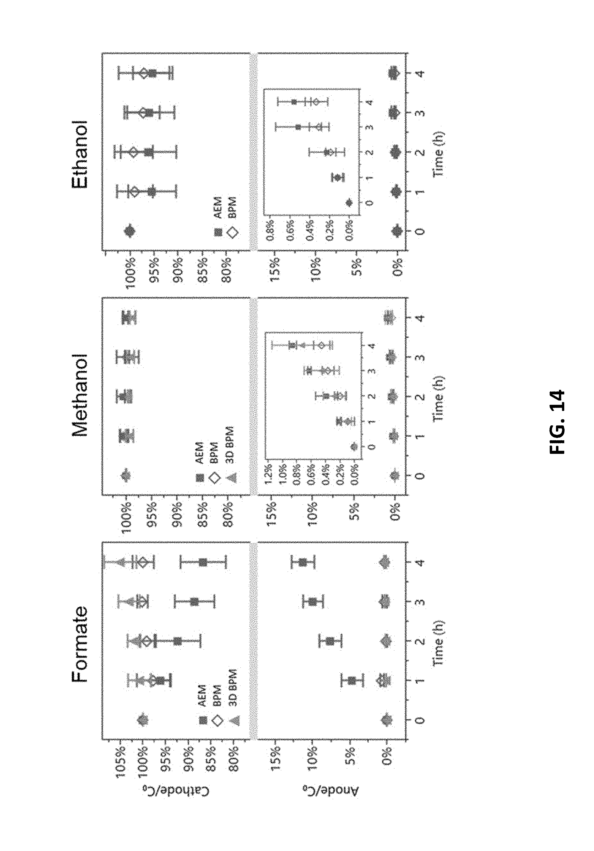
D00015
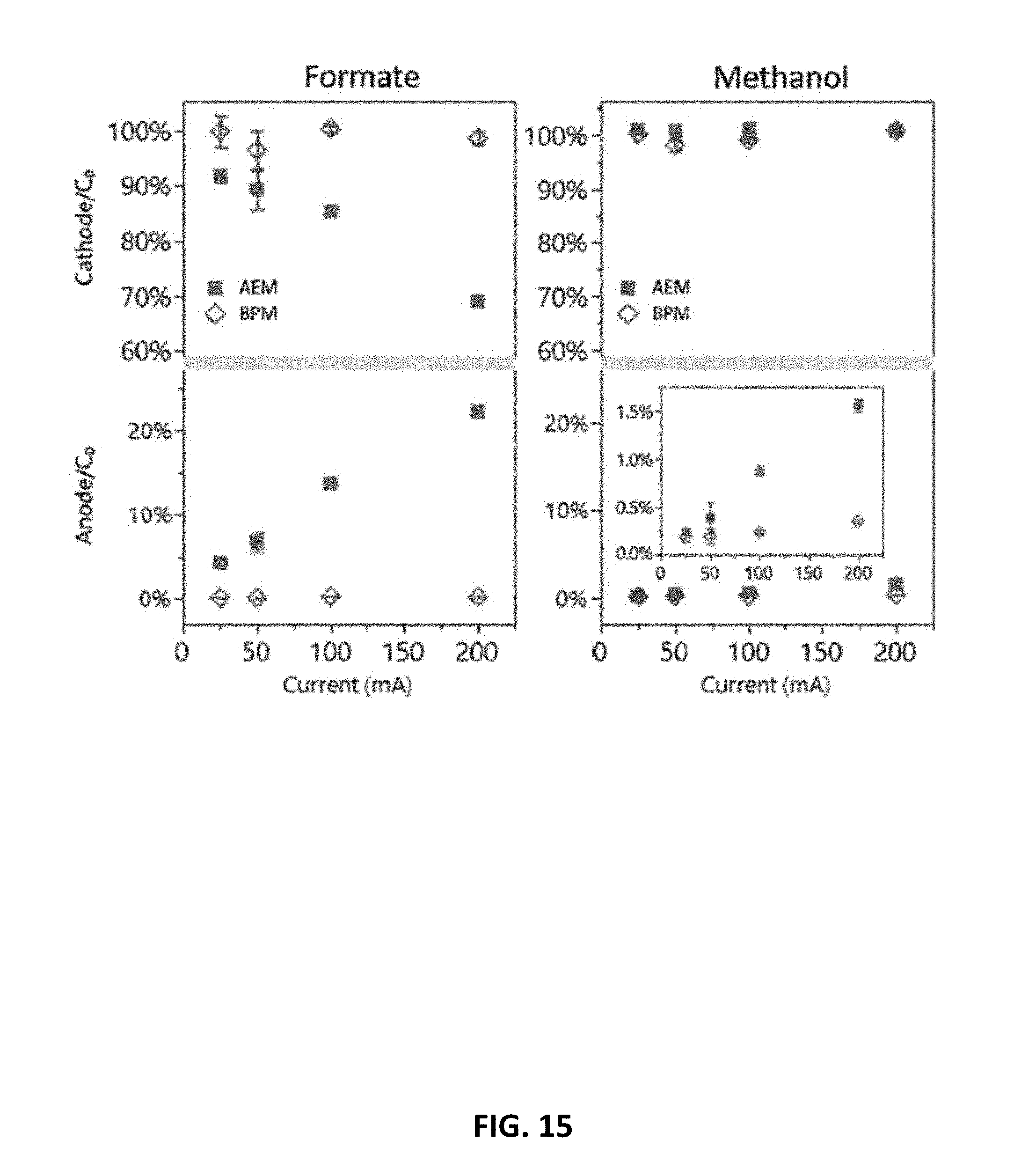
D00016

D00017

D00018

D00019
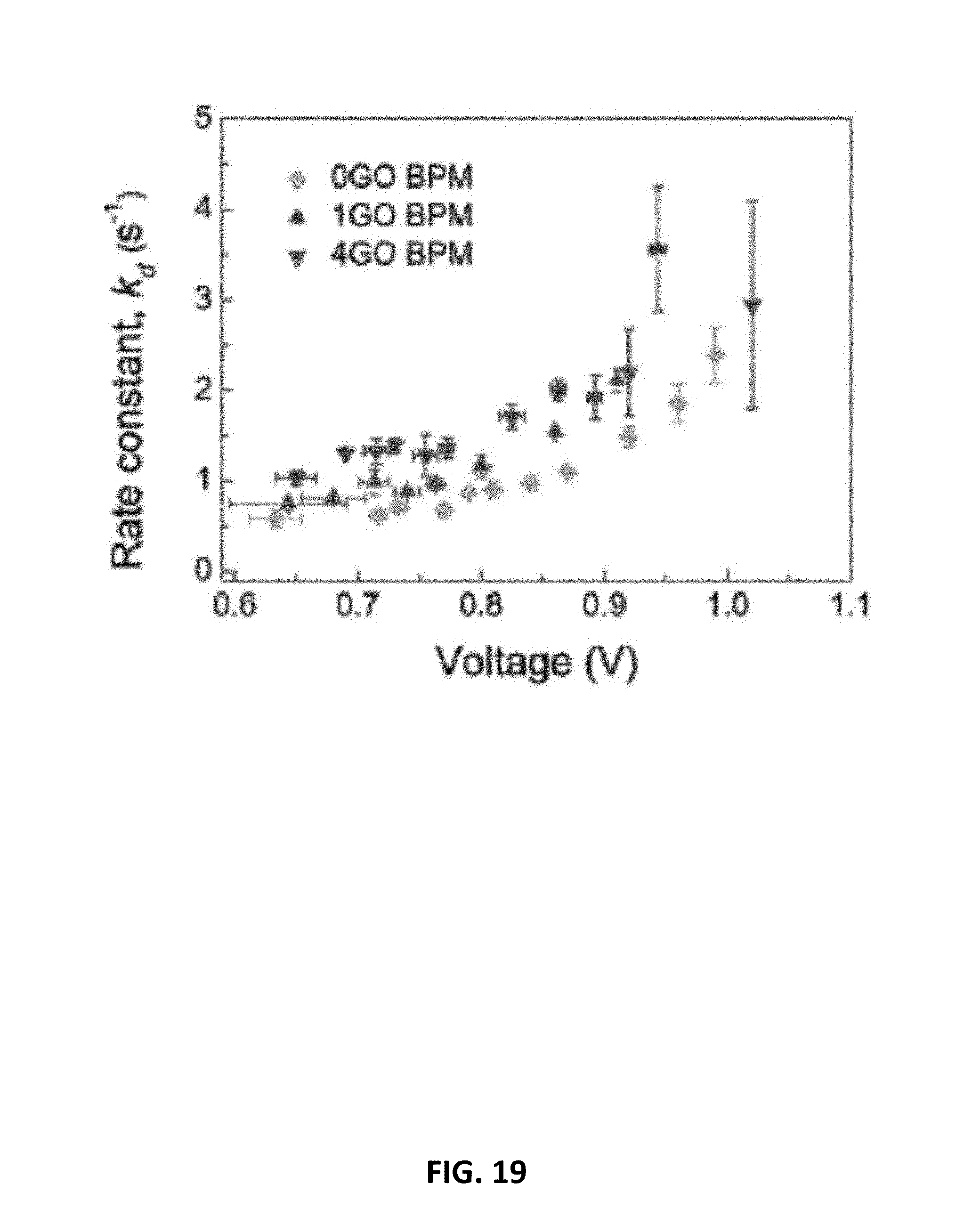
D00020
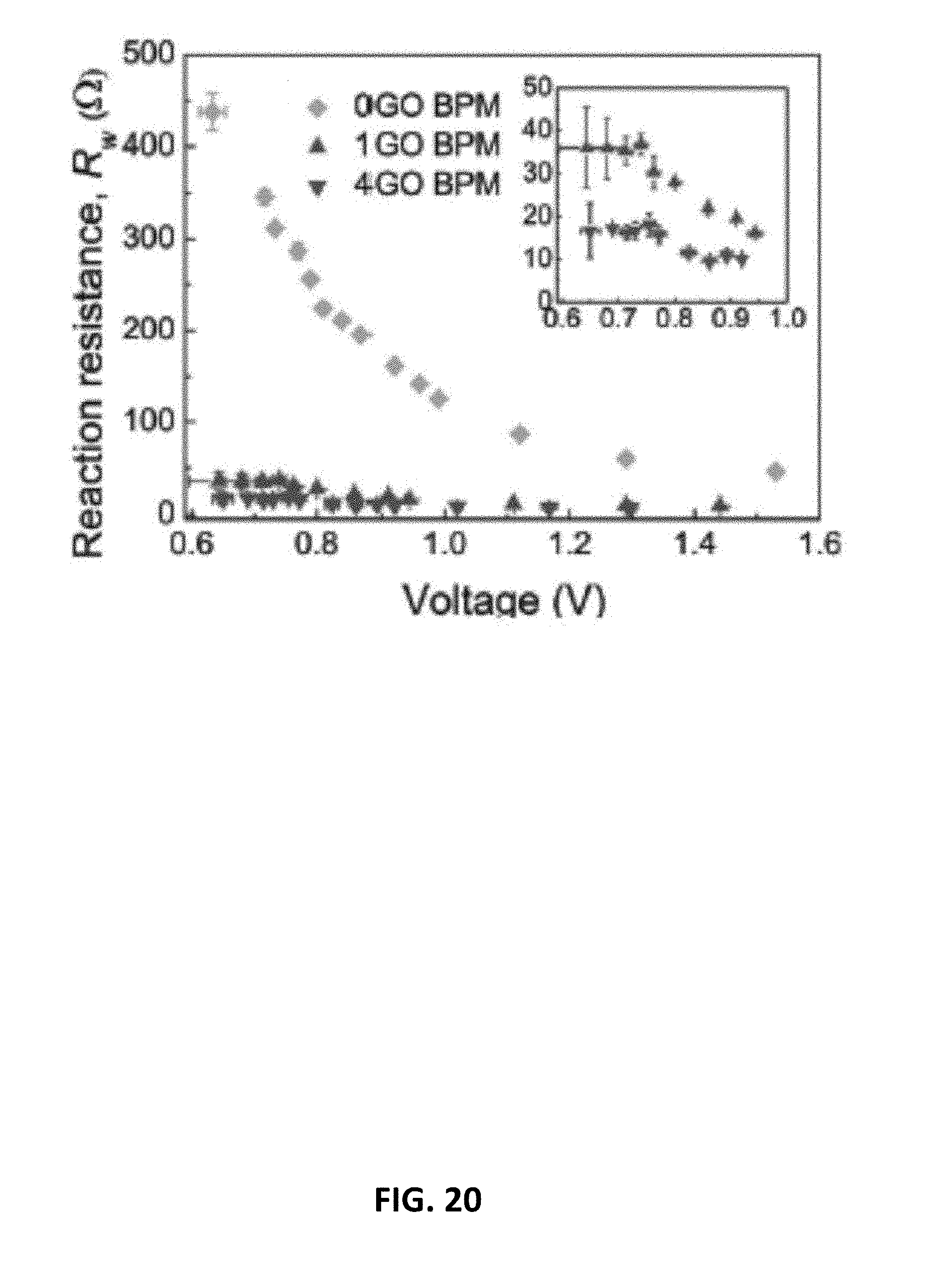
D00021

D00022

D00023

D00024
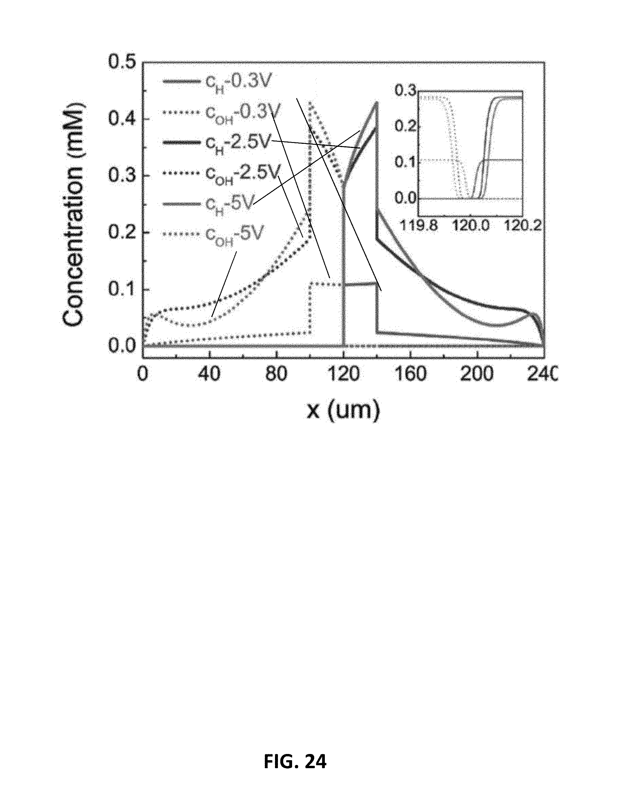
D00025

D00026
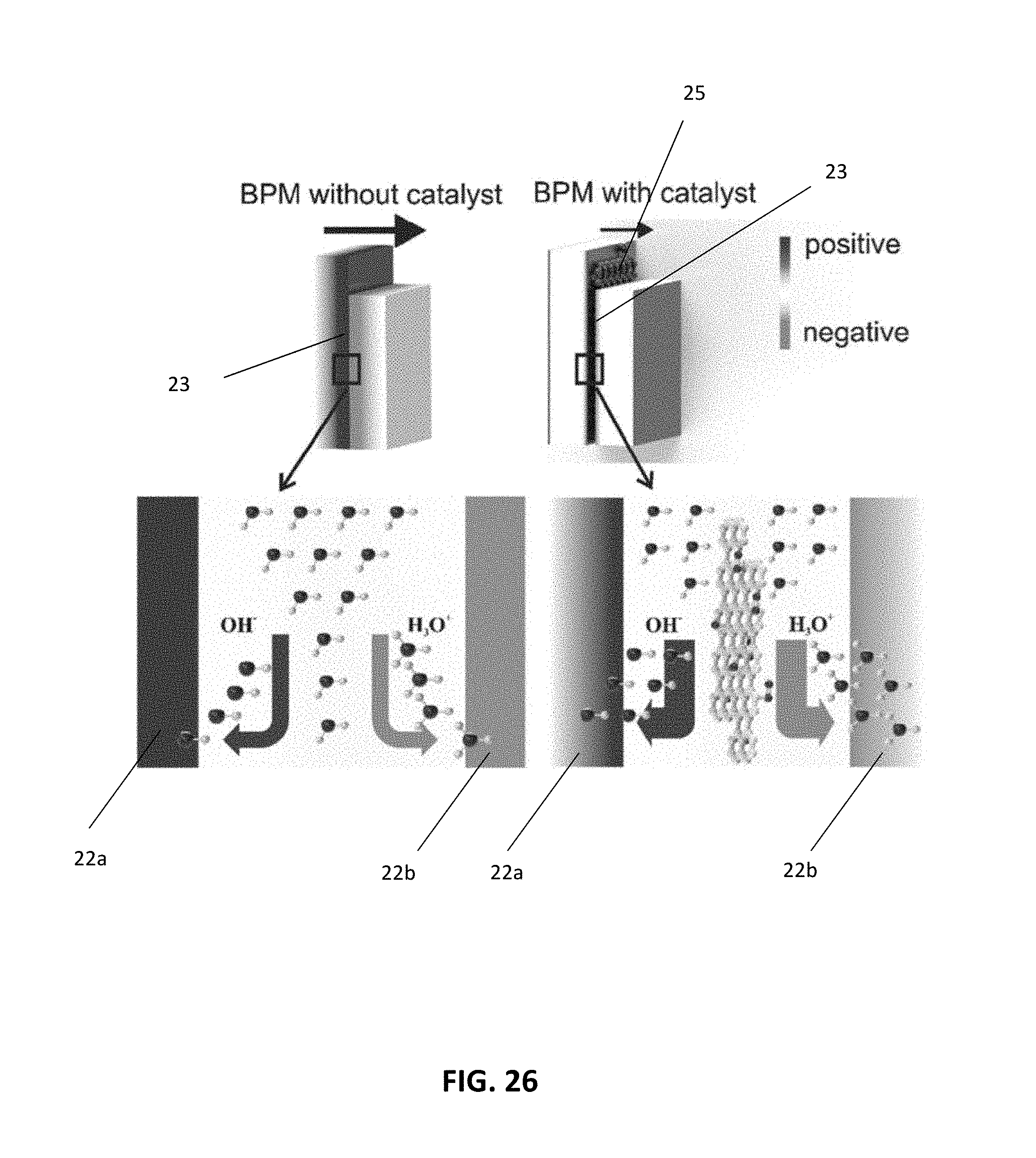
D00027

D00028

D00029

D00030

D00031

D00032
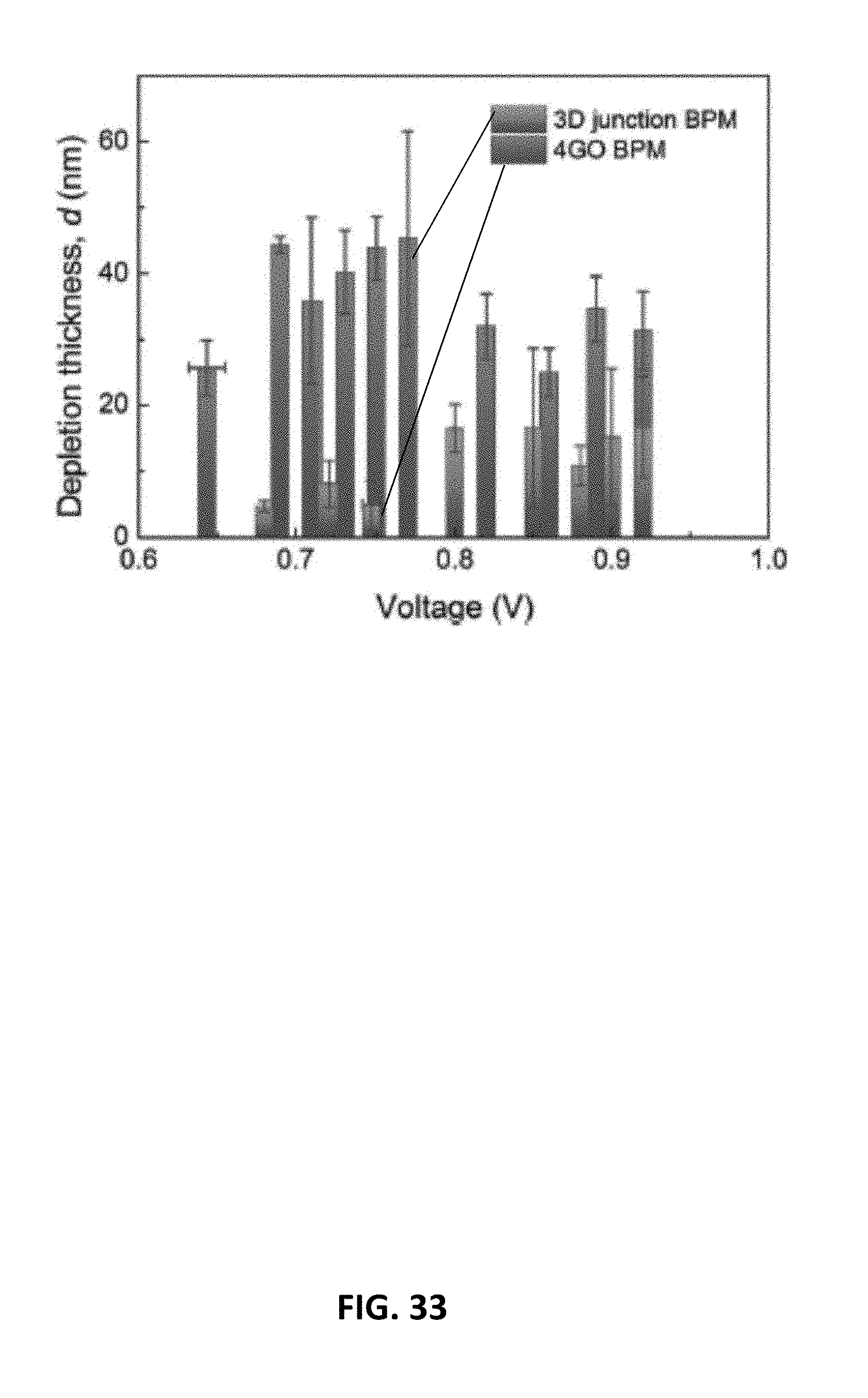
D00033

D00034


XML
uspto.report is an independent third-party trademark research tool that is not affiliated, endorsed, or sponsored by the United States Patent and Trademark Office (USPTO) or any other governmental organization. The information provided by uspto.report is based on publicly available data at the time of writing and is intended for informational purposes only.
While we strive to provide accurate and up-to-date information, we do not guarantee the accuracy, completeness, reliability, or suitability of the information displayed on this site. The use of this site is at your own risk. Any reliance you place on such information is therefore strictly at your own risk.
All official trademark data, including owner information, should be verified by visiting the official USPTO website at www.uspto.gov. This site is not intended to replace professional legal advice and should not be used as a substitute for consulting with a legal professional who is knowledgeable about trademark law.