Cord Protector
Huang; Shih Jyi
U.S. patent application number 15/795295 was filed with the patent office on 2019-05-02 for cord protector. The applicant listed for this patent is Comeup Industries Inc.. Invention is credited to Shih Jyi Huang.
| Application Number | 20190127189 15/795295 |
| Document ID | / |
| Family ID | 66245420 |
| Filed Date | 2019-05-02 |

| United States Patent Application | 20190127189 |
| Kind Code | A1 |
| Huang; Shih Jyi | May 2, 2019 |
Cord Protector
Abstract
A cord protector is combined with a cord to protect the cord. An outermost end head of the cord would revolve and is fixedly connected to the cord through a collar. The cord protector is assembled by a first protection seat and a second protection seat. The first protection seat and the second protection seat are made of flexible material resisting impact. Openings at the bottom of the first protection seat and the second protection seat co-clamp the cord. A top portion of the first protection seat is divided into two through grooves by a cross bar. Two side cord bodies of a revolving combination place of the cord respectively enter the two through grooves of the first protection seat and are joined by joining members. With the composition, it prevents collision between combined rigid components to protect the combined rigid components and operating users, thereby increasing use safety.
| Inventors: | Huang; Shih Jyi; (Taipei, TW) | ||||||||||
| Applicant: |
|
||||||||||
|---|---|---|---|---|---|---|---|---|---|---|---|
| Family ID: | 66245420 | ||||||||||
| Appl. No.: | 15/795295 | ||||||||||
| Filed: | October 27, 2017 |
| Current U.S. Class: | 1/1 |
| Current CPC Class: | F16F 1/373 20130101; B66D 1/00 20130101; B66D 1/28 20130101; B66D 2700/0183 20130101 |
| International Class: | B66D 1/28 20060101 B66D001/28; F16F 1/373 20060101 F16F001/373 |
Claims
1. A cord protector comprising a first protection seat and a second protection seat, with the first protection seat and the second protection seat made of a flexible material resisting impact, wherein an external side surface of the first protection seat is an arc cone shape having a narrow front and a wide rear, wherein an inner side of the first protection seat is a flattened shape, wherein a bottom portion of the inner side of the flattened shape is an opening, wherein two end inner sides of the opening are respectively recessed to form a joining cavity extending around and communicating with the opening, wherein the opening is extended toward but spaced from a top portion, with two through grooves obliquely extending from the opening to the top portion, with the two through grooves divided by a cross bar extending from the top portion towards but spaced from the opening, with the cross bar spaced from the joining cavity and the opening, wherein two ends of the inner side of the flattened shape are respectively opened with a joining through groove; with an external surface of the second protection seat being an arc cone having a narrow front and a wide rear, wherein an inner side of the second protection seat is a flattened shape, with a bottom portion of the inner side of the flattened shape of the second protection seat being an opening, wherein two end inner sides of the opening of the second protection seat respectively protrude to form first and second joining protrusions, with two ends of the inner side of the flattened shape of the second protection seat respectively opened with a joining through groove; with the opening of the second protection seat corresponding to the opening of the first protection seat, with the two joining protrusions of the second protection seat corresponding to the joining cavity of the first protection seat, with the joining through groove of the second protection seat corresponding to the joining through groove of the first protection seat; with the flattened shape of the second protection seat abutting the flattened shape of the first protection seat to co-form a circle cone body having a narrow front and a wide rear, with the two joining protrusions of the second protection seat entering the joining cavity of the first protection seat, with the opening of the second protection seat and the opening of the first protection seat defining a circle opening, with the cross bar of the first protection seat abutting against the flattened shape of the second protection seat, with the joining through groove of the first protection seat correspondingly communicating with the joining through groove of the second protection seat, and with a male joining member joined to a female joining member after passing through the joining through groove of the second protection seat and the joining through groove of the first protection seat.
2. The cord protector of claim 1, wherein inner side wall surfaces of the two through grooves of the first protection seat are formed with two arc grooves, with the two arc grooves being obliquely disposed; wherein the opening of the second protection seat is extended toward but spaced from a top portion of the second protection seat, with a set of arc grooves obliquely disposed on the flattened shape of the second protection seat and extending from the opening to the top portion of the second protection seat.
3. The cord protector of claim 2, wherein the set of arc grooves of the second protection seat is symmetrical with the arc grooves of the first protection seat by spacing a distance.
4. The cord protector of claim 1, wherein a cross-section of the cross bar of the first protection seat is a triangular pyramid having a narrow inside and a wide outside.
5. The cord protector of claim 1, wherein the male joining member is a screw.
6. The cord protector of claim 1, wherein the female joining member is a nut.
7. The cord protector of claim 1, further comprising a cord; and a collar revolving and fixedly connected to an outermost end head of the cord, wherein the opening of the first protection seat and the opening of the second protection seat co-clamp the cord, with the cross bar of the first protection seat passing through a revolving combination place of the cord, and with two side cord bodies of the revolving combination place of the cord respectively entering the two through grooves of the first protection seat.
8. The cord protector of claim 7, wherein the two side cord bodies of the cord are co-clamped by the two arc grooves of the first protection seat and the set of arc grooves of the second protection seat.
Description
BACKGROUND OF THE INVENTION
Field of the Invention
[0001] The present invention relates to a cord protector, and more particularly to a cord protector capable of preventing collision between combined rigid components to protect combined rigid components and operating users, thereby increasing use safety.
Description of the Related Art
[0002] A "cord" is a kind of rope that can be resisted with pull force, and the material of the cord is diversity. To pull heavy weight early, the cord can be made of using steel wire and is so called steel cable. Recently, applied chemistry is well developed, and synthetic resin material resisting pull has been developed. The material is applied to produce the cord for replacing the steel cable. The cord made of using synthetic resin is normally called as the synthetic cable having advantage of steel cable (pull resistance) without defect of steel cable (including lightweight, difficult wounding while swinging). This cord is gradually paid attention and adopted. In the disclosure, the material of the "cord" can, but not limited to, be steel cable, synthetic cable, etc.
[0003] The obvious instance of using the cord is "power winch". The "power winch" is a hoist power appliance of hoisting or laying down heavy weights and also called as "hoist machine". Places of mounting the power winch include high storied buildings' heavy goods vertical lifting or jeeps, all-terrain vehicles that drag other vehicles or self-help moving (out of danger).
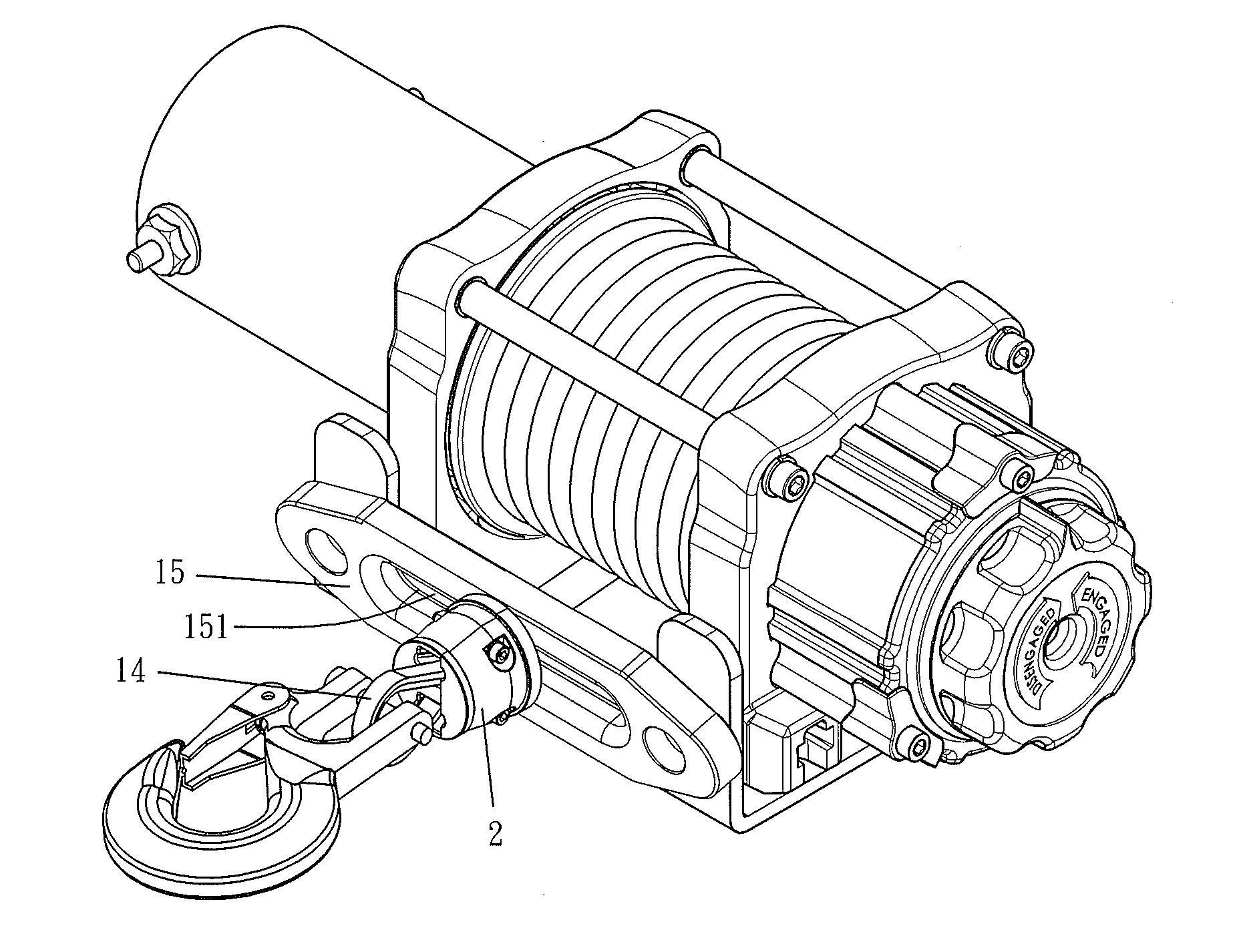
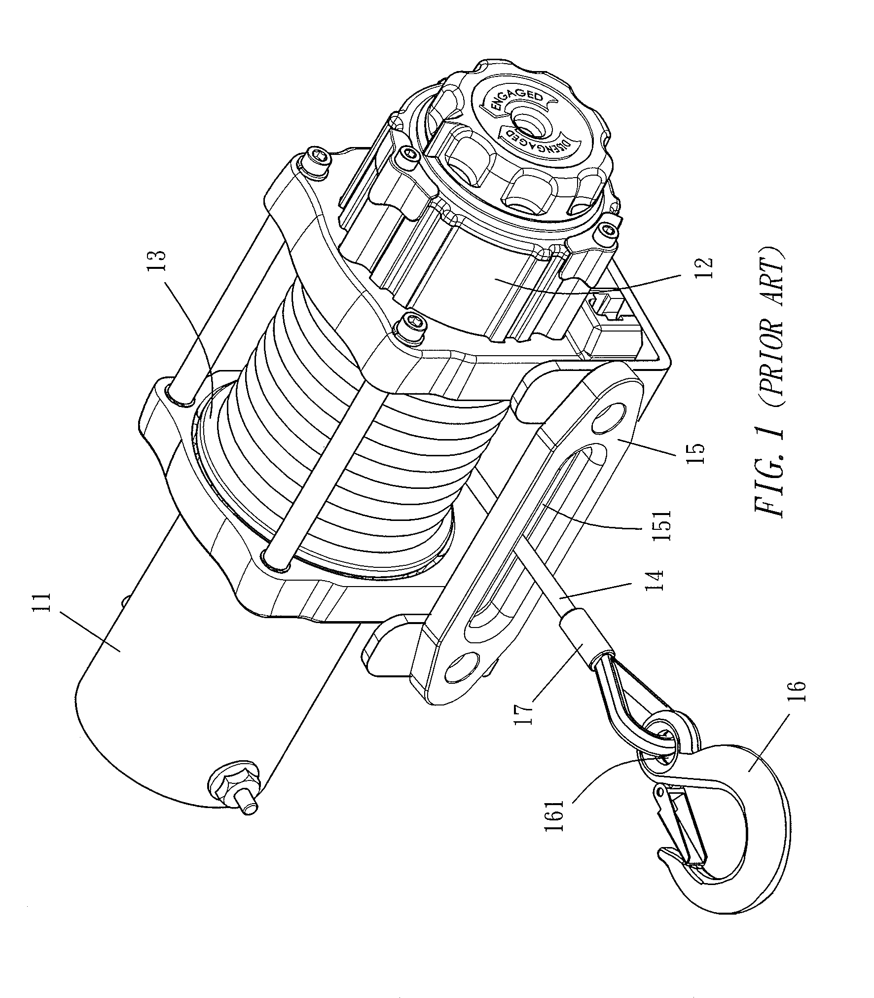
[0004] There are two types of disposing the cord on the power winch. The first type is shown in FIG. 1, a side is disposed with a power source 11 (a motor for example), and its generated power is transmitted by internal shaft core to drive a deceleration device 12 disposed at side neighbor or another side. The deceleration device 12 drives a cable pulley 13 for rotating after undergoing several levels of deceleration (planetary gear set for example) and transmission effect so that the cord 14 wound on the cable pulley 13 can perform motion of positive rotation discharging or counter revolution retracting. The cord 14 can be released or retracted through a discharging hole 151 on a discharging seat 15. The innermost end head of the cord 14 is combined with the cable pulley 13. When the cable pulley 13 rotates, the cord 14 can be wound on the cable pulley 13. The outermost end head of the cord 14 is stretched out of the discharging hole 151 of the discharging seat 15 and passes through a joining perforation 161 at a tail of a hook head 16 by way of fixedly connecting a collar 17 so that the hook head 16 locates at the front end of the cord 14. Therefore, while hoisting, the cord 14 is continuously stretched out of the discharging hole 151, and the hook head 16 at the front end executes hooking motion.
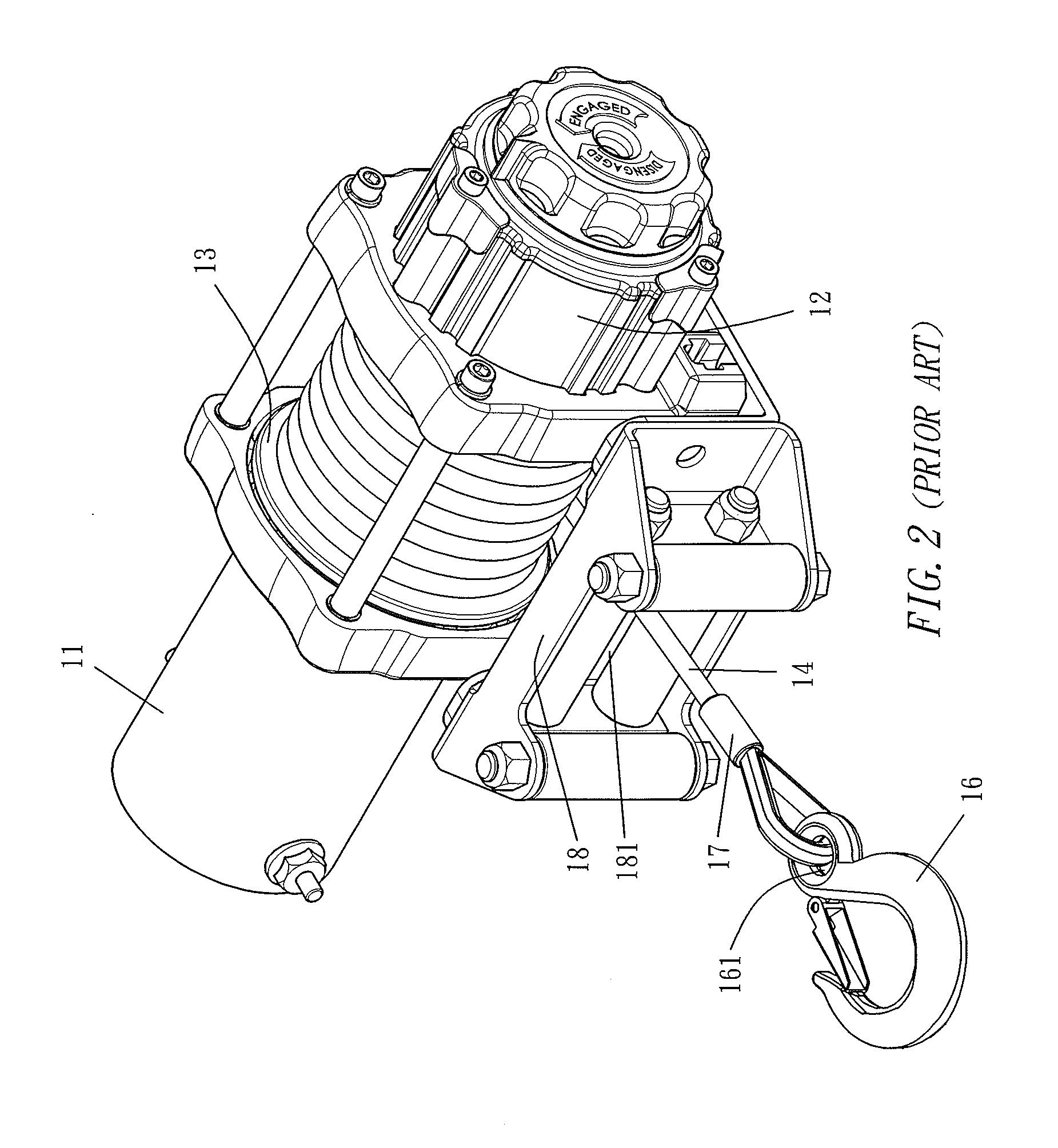
[0005] A second type is shown in FIG. 2, it still provides power through a power source 11, and a deceleration device 12 is driven through internal transmission and further drives a cable pulley 13 for rotating through several series of slow down to allow the cord 14 wound on the cable pulley 13 to perform motion of positive rotation discharging or counter rotation retracting. After the outermost end head of the cord 14 also passes through a joining perforation 161 at a tail end of a hook head 16, it is fixedly connected by a collar 17. The difference between the second type (shown in FIG. 2) and the first type (shown in FIG. 1) is that the cord 14 in the second type is discharged or retracted by the discharging hole 181 at the middle of a four-way roller set 18.
[0006] As shown in FIGS. 1, 2, the cord 14 can be stretched from the discharging hole 151 of the discharging seat 15 and can be stretched from the discharging hole 181 at the middle of the four-way roller set 18. Assembling the discharging seat 15 or the four-way roller set 18 on the power winch depends upon manufactures.
[0007] To look for rigidity, the discharging seat 15 or the four-way roller set 18 is made of metal material. For the same reason, the hook head 16 must also have rigidity since it is used for hoisting heavyweights. Therefore, the hook head 16 is also made of metal material. The cord 15 must resist pull to have flexibility and bending resistance. The cord 14 may be discharged by power while stretching out. The cord may also be pulled by labor force after turning off power. No matter the cord 14 is discharged by any force, collision or impact phenomenon basically may not occur to have extremely low risk. When the cord 14 is retracted on the cable pulley 13 of the power winch, it must be pulled back at certain speed through power. Finally, when the hook head 16 collide the discharging seat 15 or the four-way roller set 18, power then is stopped after sensing through upper limit switch or pressure switch inside the machine. In a motion of retracting the cord 14, the hook head 16 collides the discharging seat 15 or the four-way roller set 18 is taken for granted. In another word, collision is necessary to completely retract the cord 14.
[0008] Based upon the inventor of the present invention conducting researches and experiences in power winch for many years, the hook head 16 colliding the discharging seat 15 or the four-way roller set 18 has the following shortcomings:
1. Each rigidity impact between the hook head 16 ad the discharging seat 15 or between the hook head 16 and the four-way roller set 18 certainly has damage inside both or on the surface. While reaching a critical point, minor impact any one of the hook head 16, the discharging seat 15 or the four-way roller set 18 is damaged or broken to replace, and major impact industrial safety issue, such as load shedding, may occur due to damage of the hook head 16. In addition, any part may be damaged or fall to harm persons. The foregoing accident may instantly happen and is difficult to take action in early stage in advance. 2. The direct contact between the hook head 16 and the discharging seat 15 or between the hook head 16 and the four-way roller set 18 regarding the power winch disposed on the vehicle frequently generates continuous noise of "kluck-kluck-kluck", thus affecting emotion of persons in vehicle to generate tense and restlessness. It does not only influence physical and mental health but also causes accidents. The frequent rigid collision between the hook head 16 and the discharging seat 15 or between the hook head 16 and the four-way roller set 18 will affect each component's completeness of the power winch. Consequently, the mesh of internal gears of the power source 11 and/or the deceleration device 12 is sometimes not correct. Sometimes, the accuracy of the brake may be affected. The cord 14 sometimes may loose or assembling among components is not tight.
SUMMARY OF THE INVENTION
[0009] In view of the aforementioned drawbacks of the prior art, the inventor of the present invention conducted researches and experiments, and finally developed a protector in accordance with the present invention to overcome the drawbacks of the prior art. Therefore, it is an objective of the present invention to provide a cord protector capable of preventing collision between combined rigid components to protect combined rigid components and operating users, thereby increasing use safety.
[0010] To achieve the above mentioned objective, the present invention provides a cord protector composed of a first protection seat and a second protection seat, the first protection seat and the second protection seat made of a flexible material resisting impact, wherein an external side surface of the first protection seat is an arc cone shape having narrow front and wide rear condition, and an inner side of the first protection seat is a flattened shape, and a bottom portion of an inner side of the flattened shape is an opening, and two end inner sides of the opening are respectively recessed to form a joining cavity, and the opening is extended toward a top portion and expanded and divided by a cross bar to form two through grooves while reaching a top portion, and two ends of the inner side of the flattened shape are respectively opened with a joining through groove communicating toward outside; an external surface of the second protection seat being an arc cone having narrow front and wide rear condition while an inner side is a flattened shape, a bottom portion of an inner side of the flattened shape of the second protection seat being an opening, two end inner sides of the opening of the second protection seat respectively protruded to form a joining protrusion, two ends of an inner side of the flattened shape of the second protection seat respectively opened with a joining through groove communicating toward outside; the opening of the second protection seat corresponding to the opening of the first protection seat, a position and a size of the joining protrusion of the second protection seat corresponding to the joining cavity of the first protection seat, the joining through groove of the second protection seat corresponding to the joining through groove of the first protection seat; while in assembling, the flattened shape inner side of the second protection seat pasting the flattened shape inner side of the first protection seat to co-form a circle cone body having narrow front and wide rear condition, the joining protrusion of the second protection seat exactly joined to enter the joining cavity of the first protection seat for stay one by one, the opening of the second protection seat and the opening of the first protection seat co-surround a circle opening, the cross bar of the first protection seat exactly leaning against the flattened shape inner side of the second protection seat, the joining through groove of the first protection seat correspondingly communicating with the joining through groove of the second protection seat, a male joining member joined to a female joining member after passing through the joining through groove of the second protection seat and the joining through groove of the first protection seat.
[0011] The above mentioned cord protector, wherein an inner side wall surface of the through groove of the first protection seat is formed with an arc groove obliquely disposed; and the opening of the second protection seat is formed with a set of arc grooves obliquely disposed on a wall surface of the flattened shape inner side after extending a small section toward a top portion.
[0012] The above mentioned cord protector, wherein the arc groove of the second protection seat is symmetrical the arc groove of the first protection seat by spacing a distance.
[0013] The above mentioned cord protector, wherein a cross-section of the cross bar of the first protection seat is a triangular pyramid having narrow inside and wide outside condition.
[0014] The above mentioned cord protector, wherein the male joining member is a screw.
[0015] The above mentioned cord protector, wherein the female joining member is a nut.
[0016] The above mentioned cord protector is combined with a cord to protect the cord, wherein an outermost end head of the cord revolving and fixedly connected to the cord through a collar, the opening of the first protection seat and the opening of the second protection seat co-clamp the cord, the cross bar of the first protection seat passing through a revolving combination place of the cord, two side cord bodies of the revolving combination place of the cord respectively entering the two through grooves of the first protection seat for stay.
[0017] The above mentioned cord protector, wherein the cord body of the cord is co-clamped by the arc groove of the first protection seat and the arc groove of the second protection seat.
BRIEF DESCRIPTION OF THE DRAWINGS
[0018] FIG. 1 is a three-dimensional drawing of installing cord on conventional power winch in accordance with a first type;
[0019] FIG. 2 is a three-dimensional drawing of installing cord on conventional power winch in accordance with a second type;
[0020] FIG. 3 is a three-dimensional decomposition chart at front view angle according to the embodiment of the present invention;
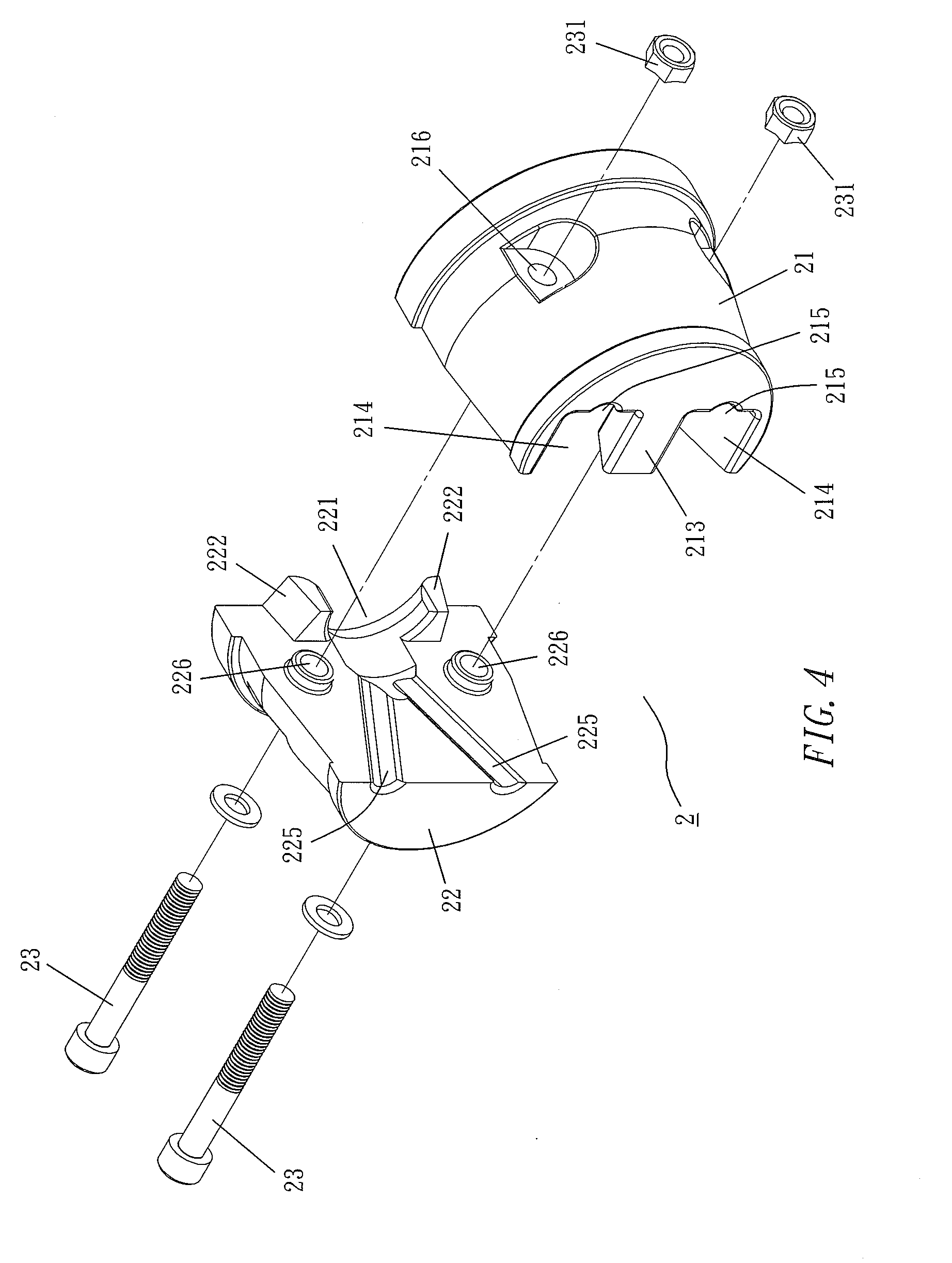
[0021] FIG. 4 is a three-dimensional decomposition chart at rear view angle according to the embodiment of the present invention;
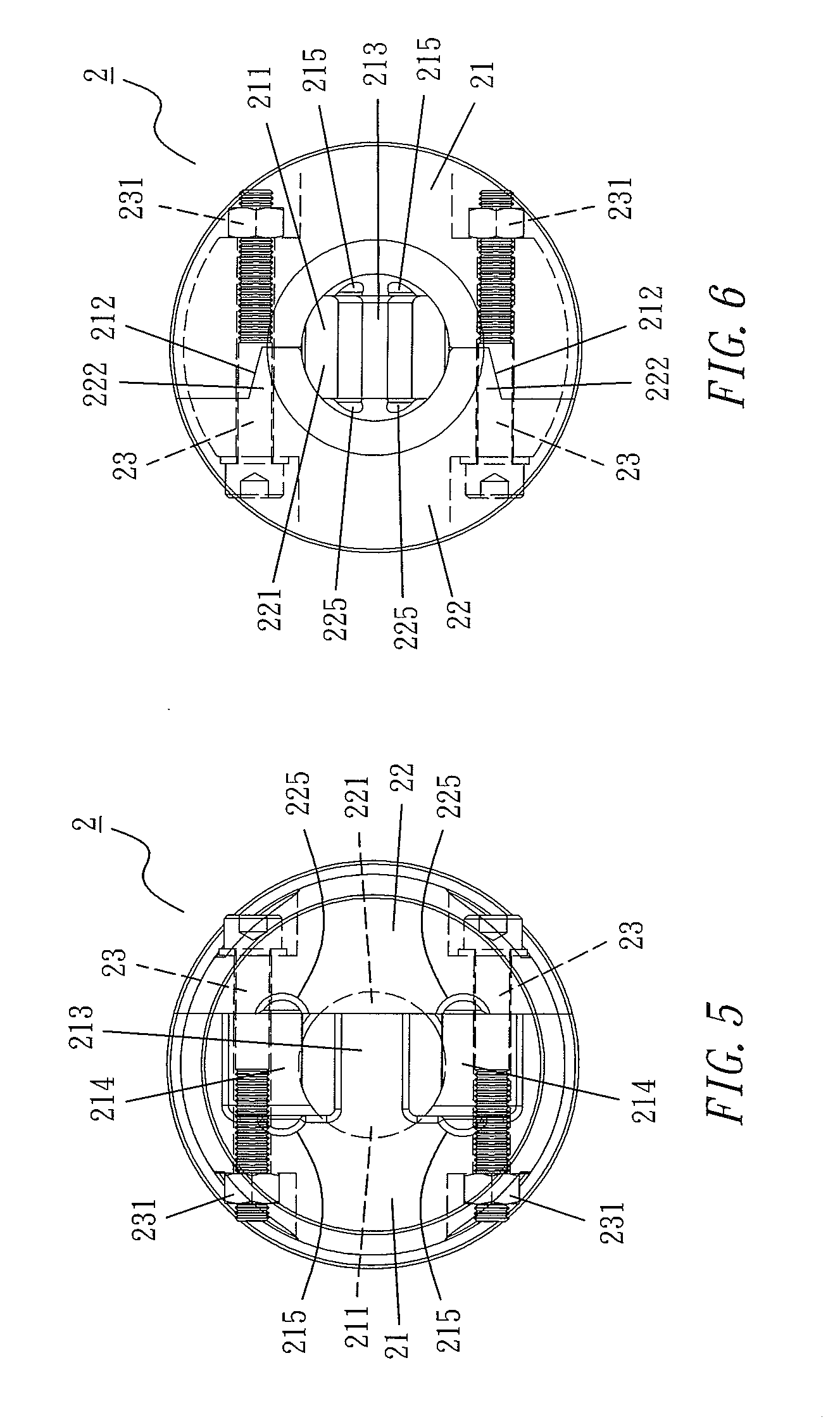
[0022] FIG. 5 is an assembled front view drawing according to the embodiment of the present invention;
[0023] FIG. 6 is an assembled rear view drawing according to the embodiment of the present invention;
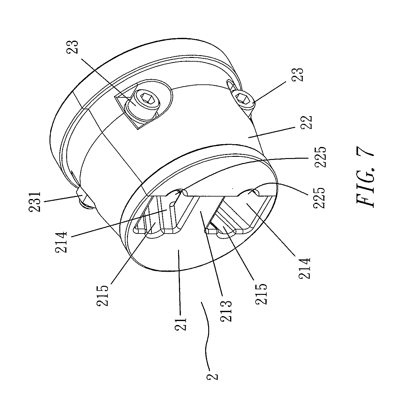
[0024] FIG. 7 is an assembled three-dimensional drawing according to the embodiment of the present invention;
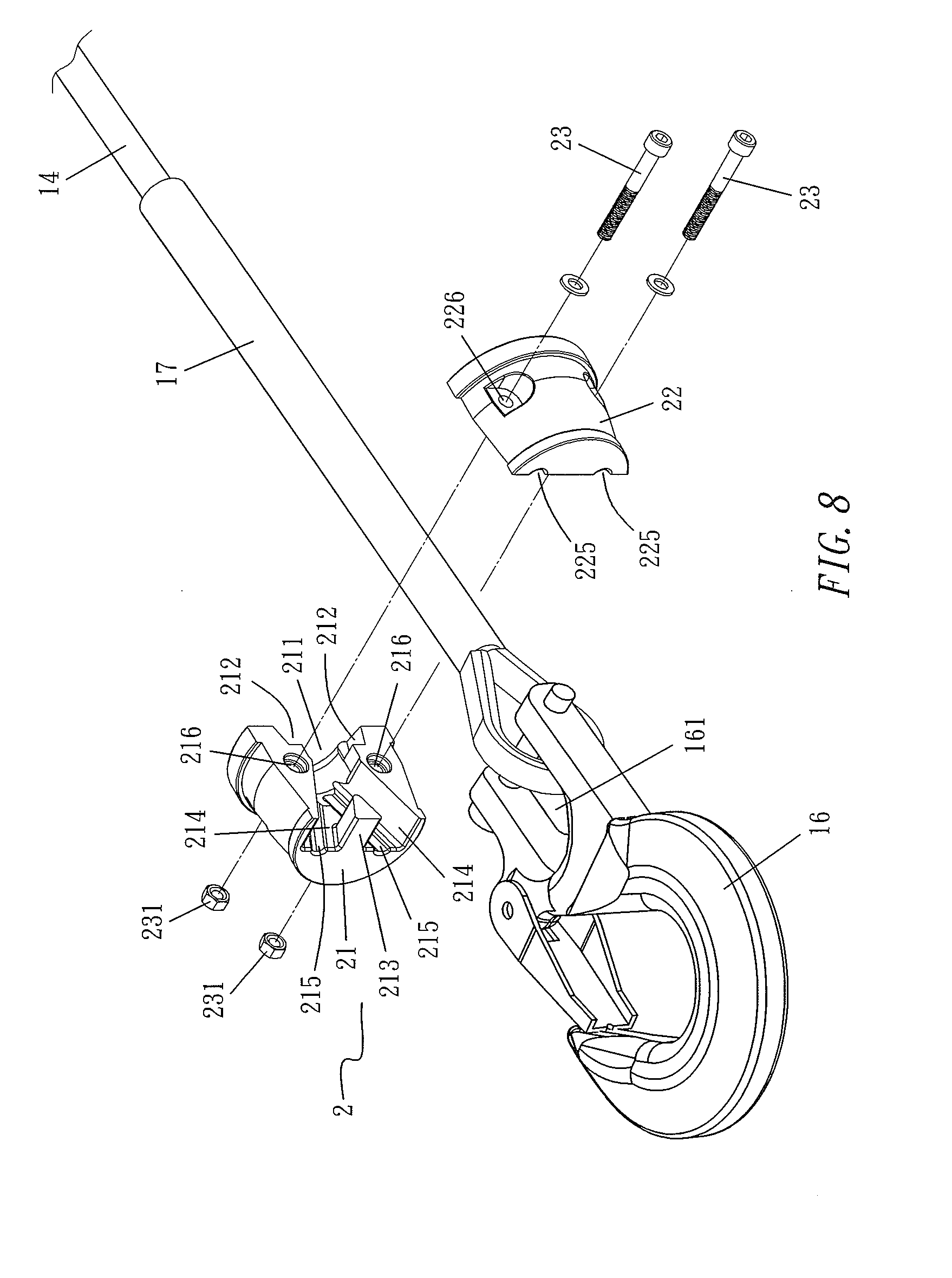
[0025] FIG. 8 is a decomposition chart of a cord and a hook head according to the embodiment of the present invention;
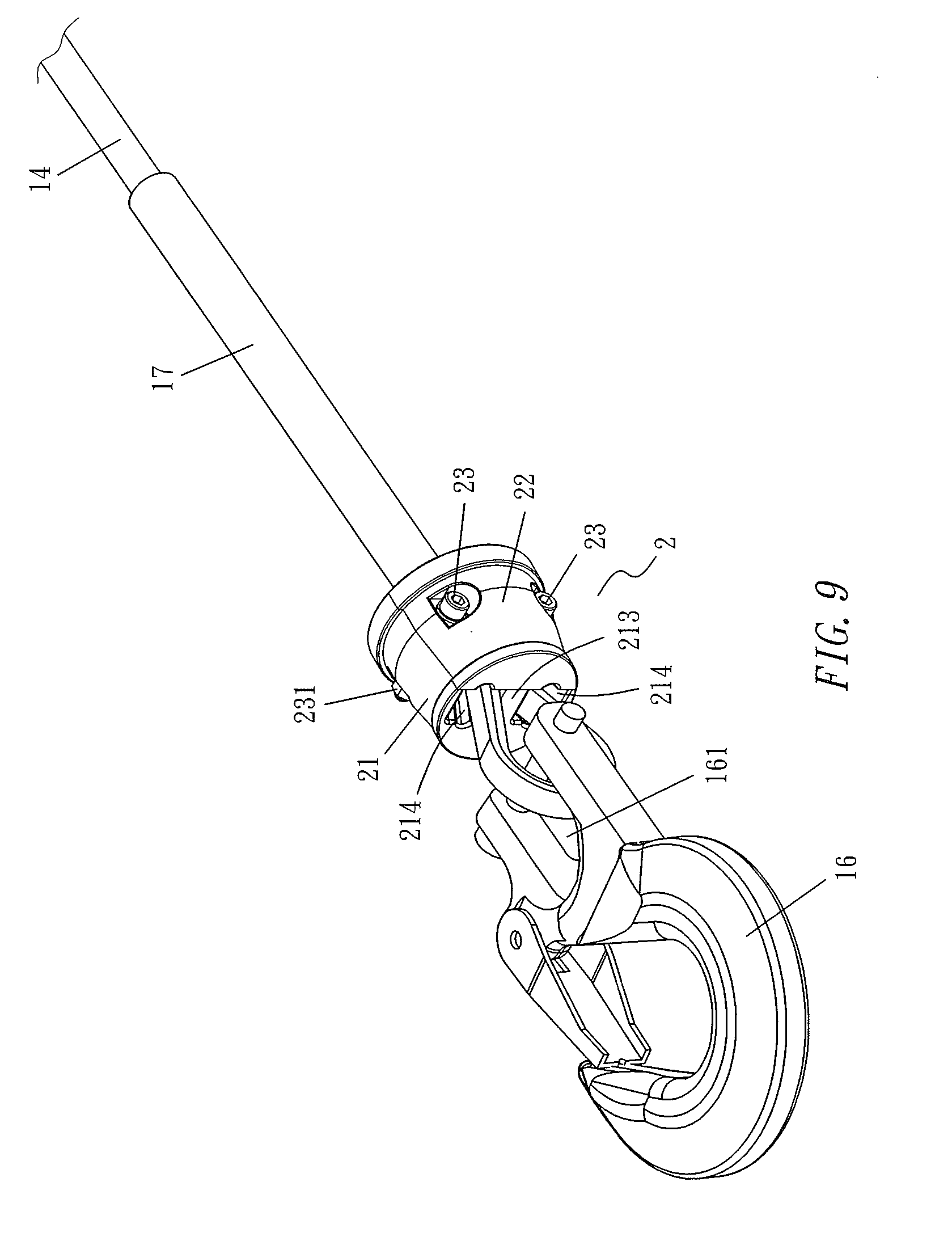
[0026] FIG. 9 is an assembled three-dimensional drawing of a cord and a hook head according to the embodiment of the present invention;
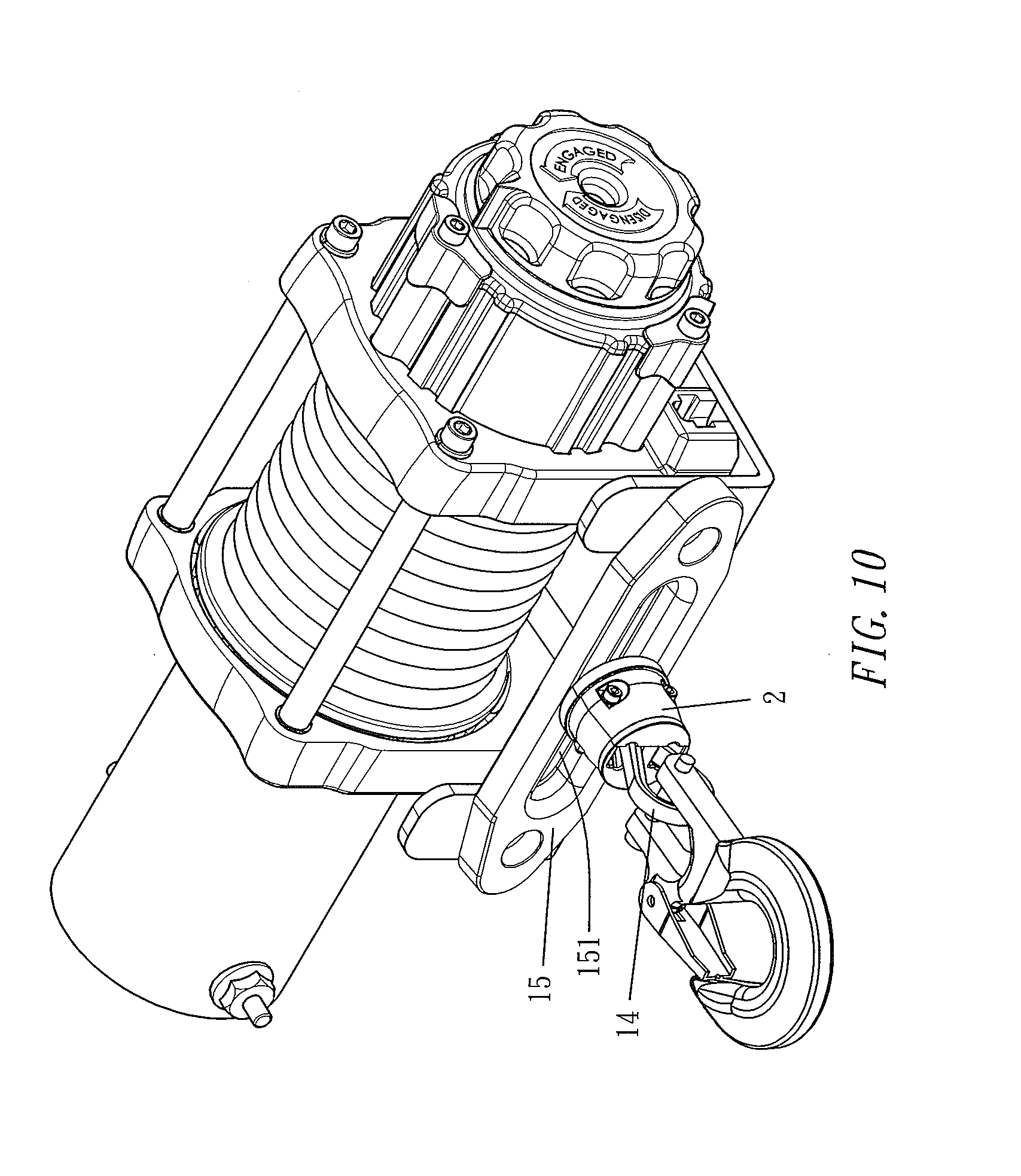
[0027] FIG. 10 is a three-dimensional drawing of installing on a power winch at first type according to the embodiment of the present invention;
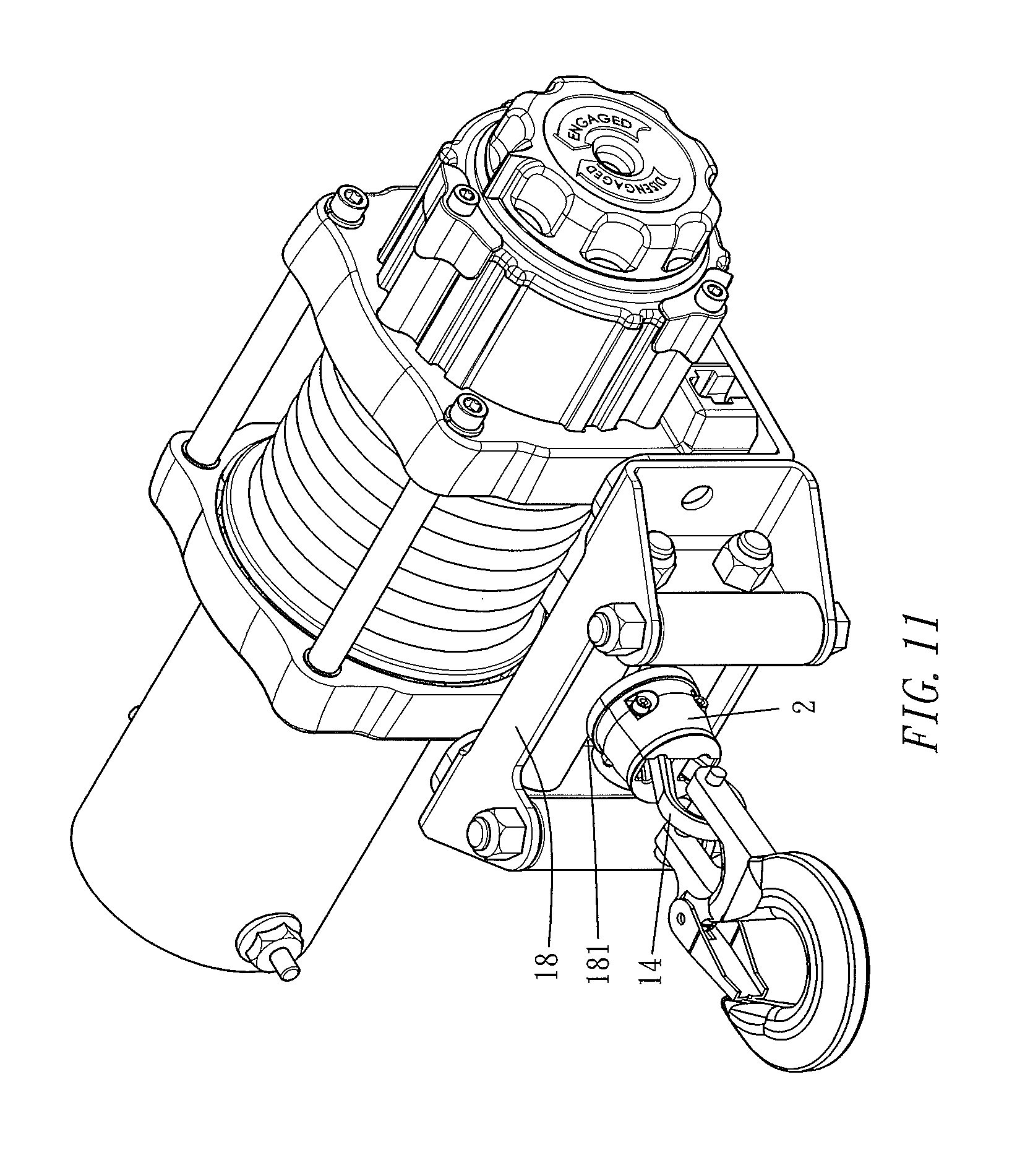
[0028] FIG. 11 is a three-dimensional drawing of installing on a power winch at second type according to the embodiment of the present invention.
DETAILED DESCRIPTION OF THE PREFERRED EMBODIMENTS
[0029] The technical characteristics, contents, advantages and effects of the present invention will be apparent with the detailed description of a preferred embodiment accompanied with related drawings as follows.
[0030] With reference to FIGS. 3-7 for a cord protector 2 according to the embodiment of the present invention, the structure is formed by co-assembling a first protection seat 21 and a second protection seat 22, and the first protection seat 21 and the second protection seat 22 are made of a flexible material that resists impact, such as synthetic rubber, rubber doped with synthetic resin, etc., wherein an external side surface of the first protection seat 21 is a circle arc cone having narrow front and wide rear condition while inner side is a flattened shape. A bottom of the flattened inner side is an opening 211. Two end inner sides of the opening 211 are respectively recessed to form a joining cavity 212. The opening 211 is extended toward the top portion and enlarged and, while reaching the top portion, divided by a cross bar 213 to form two through grooves 214. The lateral cross-section of the cross bar 213 is a triangular pyramid having narrow inside and wide outside condition. An arc groove 215 obliquely disposed is formed on the inner side wall of each through groove 214. Two ends at the flattened inner side are respectively opened with a joining through groove 216 communicating toward outside.
[0031] An external side surface of the second protection seat 22 is also a circle arc cone having narrow front and wide rear condition while an inner side is also a flattened shape. A bottom of the flattened inner side is an opening 221. Two end inner sides of the opening 221 are respectively protruded to form joining protrusions 222. The opening 221 is formed with a set of arc grooves 225 obliquely disposed on the wall surface of the flattened inner side after extending a small section toward the top portion. Two ends of the flattened inner side are respectively disposed with a joining through groove 226 communicating toward the outside, wherein the opening 221 of the second protection seat 22 corresponds to the opening 211 of the first protection seat 21. The position and size of the joining protrusion 222 of the second protection seat 22 corresponds to the joining cavity 212 of the first protection seat 21. The arc groove 225 of the second protection seat 22 is symmetric with the arc groove 215 of the first protection seat 21 by spacing an interval. The joining through groove 226 of the second protection seat 22 corresponds to the joining through groove 216 of the first protection seat 21.
[0032] While in assembling, the flattened inner side of the second protection seat 22 is pasted to the flattened inner side of the first protection seat 21 to co-form a circle cone body having narrow front and wide rear condition as shown in FIGS. 5, 6, 7. In the process, the joining protrusion 222 of the second protection seat 22, one by one exactly enters in the joining cavity 212 of the first protection seat 21 for stay, and a circle opening is formed by co-surrounding the opening 221 of the second protection seat 22 and the opening 211 of the first protection seat 21 as shown in FIG. 6. At the same time, the cross bar 213 of the first protection seat 21 exactly leans against the flattened inner side of the second protection seat 22 as shown in FIG. 5. Moreover, the joining through groove 216 of the first protection seat 21 correspondingly penetrates through the joining through groove 226 of the second protection seat 22. Accordingly, a set of male joining members 23 (screws for example) is joined with a set of female joining members 231 (nuts for example) after passing through the joining through grooves 226, 216 so that the first protection seat 21 and the second protection seat 22 are assembled to form a completely cord protector 2.
[0033] The cord protector 2 is specifically designed to combine with a cord 14 and to protect the cord 14. With reference to FIGS. 8, 9, before the cord protector 2 is not joined with the female joining members 231 (nuts for examples) through the male joining members 23 (screws for example), the collar 17 outside the cord 14 can be co-clamped by the opening 211 of the first protection seat 21 and the opening 221 of the second protection seat 22. The outermost end head of the cord 14 revolves to fasten the cord 14 through the collar 17 after normally passing through a joining perforation 161 at the tail end of a hook head 16, and the hook head 16 is located at the front end of the cord 14. Accordingly, the opening 211 of the first protection seat 21 and the opening 221 of the second protection seat 22 exactly co-clamp the collar 17. At the same time, the cross bar 213 of the first protection seat 21 passes through a revolving combination place of the cord 14 so that cord bodies of the cord 14 at two sides respectively enter in the two through grooves 214 of the first protection seat 21 for stay after revolving. If the cord body of the cord 14 is in larger wide condition, it is co-supported and clamped by the arc groove 215 of the first protection seat 21 and the arc groove 225 of the second protection seat 22. After completing the motion of co-clamping the collar 17 through the first protection seat 21 and the second protection seat 22 and enabling the cross bar 213 of the first protection seat 21 passing through the revolving combination place of the cord 14, the male joining members 23 (screw for example) is joined with the female joining members 231 (nut for example) such that the first protection seat 21 and the second protection seat 22 are not only assembled as the completely cord protector 2 but also combined with the cord 14 so as to protect the cord 14.
[0034] With references to FIGS. 8, 9, the cord protector 2 disclosed by the invention is combined with the revolving combination place of the cord 14, and the outermost end of the cord 14 would pass through the joining perforation 161 at the tail end of a hook head 16 to achieve combination. The cord 14 is also combined on other appliances. Herein taking the cord 14 combined to the "power winch" as an example, by comparing with two types of installing cord on the conventional power winch shown in the foregoing FIGS. 1, 2, with references to FIGS. 10, 11, FIG. 10 is in contrast with the foregoing FIG. 1, the cord 14 performs a motion of discharging or withdrawing via the cable entry 151 of a discharging seat 15. However, the revolving combination place of the cord 14 shown in FIG. 10 is further combined with the cord protector 2 disclosed in the invention. The FIG. 11 is in contrast with the foregoing FIG. 2, the cord 14 carries out a motion of discharging or withdrawing via the cable entry 181 of a four-way roller set 18. The revolving combination place of the cord 14 shown in the FIG. 11 is also combined with the cord protector 2 disclosed in the invention.
[0035] With references to FIGS. 10, 11, after the revolving combination place of the cord 14 of the power winch is combined with the cord protector 2 disclosed by the invention, finally the cord protector 2 collides the discharging seat 15 or the four-way roller set 18 when the cord 14 is withdrawn via power. Therefore, loud noise generated from collision between metals in prior art has been basically eliminated so as to have the following efficacies:
[0036] 1. Since the cord protector 2 is made of flexible material resisting impact, every impact force on the discharging seat 15 or the four-way roller set 18 will be absorbed and buffered by the cord protector 2 to protect any of the hook head 16, the discharging seat 15 or the four-way roller set 18 so that industrial safety issue can be prevented from occurring to protect the operator.
[0037] 2. While retracting the cord 14, the cord protector 2 is fastened between the hook head 16 and the discharging seat 15 or between the hook head 16 and the four-way roller set 18 to avoid direct contact between metals. Therefore, it can eliminate possibly generated noise during vehicle idling such that emotion of persons in vehicle will not be influenced.
[0038] 3. While retracting the cord 14, the cord protector 2 is fastened between the hook head 16 and the discharging seat 15 or between the hook head 16 and the four-way roller set 18 to avoid direct contact between metals. Therefore, it can protect completeness of each component of power winch and operation accuracy.
[0039] The cord protector 2 disclosed by the present invention does not only have novelty and non-obviousness but also has feature of preventing collision between combined rigid components to protect the combined rigid components and operating users so as to achieve progressive effect of use safety and satisfies patentability.
[0040] While the present invention has been described by means of specific embodiments, numerous modifications and variations could be made thereto by those skilled in the art without departing from the scope and spirit of the invention set forth in the claims.
* * * * *
D00000
D00001
D00002
D00003
D00004
D00005
D00006
D00007
D00008
D00009
D00010
XML
uspto.report is an independent third-party trademark research tool that is not affiliated, endorsed, or sponsored by the United States Patent and Trademark Office (USPTO) or any other governmental organization. The information provided by uspto.report is based on publicly available data at the time of writing and is intended for informational purposes only.
While we strive to provide accurate and up-to-date information, we do not guarantee the accuracy, completeness, reliability, or suitability of the information displayed on this site. The use of this site is at your own risk. Any reliance you place on such information is therefore strictly at your own risk.
All official trademark data, including owner information, should be verified by visiting the official USPTO website at www.uspto.gov. This site is not intended to replace professional legal advice and should not be used as a substitute for consulting with a legal professional who is knowledgeable about trademark law.