Image Forming Apparatus And Feeding Apparatus
Ochi; Junichi ; et al.
U.S. patent application number 16/165930 was filed with the patent office on 2019-05-02 for image forming apparatus and feeding apparatus. The applicant listed for this patent is CANON KABUSHIKI KAISHA. Invention is credited to Miho Kaiga, Junichi Ochi, Yohei Suzuki.
| Application Number | 20190127166 16/165930 |
| Document ID | / |
| Family ID | 66245156 |
| Filed Date | 2019-05-02 |


View All Diagrams
| United States Patent Application | 20190127166 |
| Kind Code | A1 |
| Ochi; Junichi ; et al. | May 2, 2019 |
IMAGE FORMING APPARATUS AND FEEDING APPARATUS
Abstract
A feeding apparatus includes a feeding member to feed a recording material stacked on a stacking portion, a first conveyance member, a separation member to form a nip portion with the first conveyance member and separate a plurality of recording materials at the nip portion, a second conveyance member, a detection unit, and a control unit. The control unit controls to feed a stacked first recording material and, after a first recording material rear end passes through the feeding member, the control unit controls to feed a stacked second recording material while partially overlapped with the first recording material and thereby the first recording material rear end passes through the nip portion after a second recording material leading end passes through the nip portion. The control unit controls so that the second recording material is stopped before the second recording material leading end reaches the second conveyance member.
| Inventors: | Ochi; Junichi; (Mishima-shi, JP) ; Suzuki; Yohei; (Mishima-shi, JP) ; Kaiga; Miho; (Suntou-gun, JP) | ||||||||||
| Applicant: |
|
||||||||||
|---|---|---|---|---|---|---|---|---|---|---|---|
| Family ID: | 66245156 | ||||||||||
| Appl. No.: | 16/165930 | ||||||||||
| Filed: | October 19, 2018 |
| Current U.S. Class: | 1/1 |
| Current CPC Class: | B65H 7/12 20130101; B65H 2403/724 20130101; B65H 2513/53 20130101; B65H 2403/732 20130101; B65H 3/5215 20130101; B65H 2511/528 20130101; B65H 5/062 20130101; B65H 7/06 20130101; B65H 5/24 20130101; B65H 3/0669 20130101; B65H 2701/1311 20130101; B65H 2701/1313 20130101; B65H 2513/514 20130101; B65H 2701/1311 20130101; B65H 2220/01 20130101; B65H 2701/1313 20130101; B65H 2220/01 20130101; B65H 2513/53 20130101; B65H 2220/03 20130101; B65H 2511/528 20130101; B65H 2220/03 20130101; B65H 2513/514 20130101; B65H 2220/02 20130101 |
| International Class: | B65H 7/12 20060101 B65H007/12; B65H 3/06 20060101 B65H003/06; B65H 5/06 20060101 B65H005/06 |
Foreign Application Data
| Date | Code | Application Number |
|---|---|---|
| Oct 27, 2017 | JP | 2017-207963 |
Claims
1. A feeding apparatus comprising: a feeding member configured to feed a recording material stacked on a stacking portion; a first conveyance member configured to convey the recording material fed by the feeding member; a separation member configured to form a nip portion with the first conveyance member and separate a plurality of recording materials at the nip portion; a second conveyance member configured to convey the recording material conveyed by the first conveyance member; a detection unit configured to be disposed between the first conveyance member and the second conveyance member and to detect the recording material; and a control unit configured to control the feeding member and the first conveyance member so that a first recording material that is stacked on the stacking portion is fed by the feeding member and, after a rear end of the first recording material passes through the feeding member, a second recording material that is stacked on the stacking portion is fed by the feeding member while being partially overlapped with the first recording material and thereby the rear end of the first recording material passes through the nip portion after a leading end of the second recording material passes through the nip portion, and control the feeding member and the first conveyance member so that the second recording material is stopped before the leading end of the second recording material reaches the second conveyance member, wherein, after the first recording material is conveyed by the second conveyance member and the first recording material and the second recording material that are partially overlapped are separated from each other, the control unit changes a feeding condition for the feeding member and the first conveyance member to feed the stopped second recording material in accordance with a detection result of the second recording material by the detection unit.
2. The feeding apparatus according to claim 1, wherein a timing at which feeding of the second recording material is started is the feeding condition and the control unit changes the timing at which feeding of the second recording material is started.
3. The feeding apparatus according to claim 2, wherein the control unit starts the feeding of the second recording material at a predetermined timing in a case where the detection unit detects the second recording material, and starts the feeding of the second recording material at a timing earlier than the predetermined timing in a case where the detection unit does not detect the second recording material.
4. The feeding apparatus according to claim 1, wherein a feeding speed of the second recording material is the feeding condition and the control unit changes the feeding speed of the second recording material.
5. The feeding apparatus according to claim 4, wherein the control unit feeds the second recording material at a predetermined speed in a case where the detection unit detects the second recording material, and feeds the second recording material at a speed faster than the predetermined speed in a case where the detection unit does not detect the second recording material.
6. The feeding apparatus according to claim 1, further comprising: a motor configured to drive the feeding member, the first conveyance member, and the second conveyance member; and an electromagnetic clutch configured to transmit or intercept driving force from the motor with respect to the feeding member and the first conveyance member.
7. The feeding apparatus according to claim 1, further comprising: a first motor configured to drive the feeding member and the first conveyance member; and a second motor configured to drive the second conveyance member.
8. The feeding apparatus according to claim 1, wherein the detection unit includes a sensor arm configured to rotate by being in contact with a recording material that is conveyed and includes an encoder configured to detect a rotation angle of the sensor arm, and wherein the control unit obtains a position of the leading end of the stopped second recording material from the rotation angle of the sensor arm, which is detected by the encoder, and changes the feeding condition in accordance with the position of the leading end of the second recording material.
9. The feeding apparatus according to claim 1, wherein the detection unit includes a transmission unit configured to transmit an ultrasonic wave and includes a reception unit configured to receive the ultrasonic wave that is transmitted by the transmission unit and passes through plural recording materials, wherein the detection unit is configured to detect, based on the ultrasonic wave received by the reception unit, a timing at which the leading end of the second recording material that is conveyed while being partially overlapped with the first recording material passes through the detection unit, and wherein the control unit is configured to obtain a position of the leading end of the second recording material from the timing at which the leading end of the second recording material passes through the detection unit, and to change the feeding condition in accordance with the position of the leading end of the second recording material.
10. The feeding apparatus according to claim 1, wherein, in a case where the first recording material is fed to the nip portion by the feeding member, the separation member rotates in a predetermined direction to feed the first recording material, wherein, in a case where the second recording material is fed to the nip portion by the feeding member while the first recording material is held by the nip portion, the separation member rotates in the predetermined direction to feed the second recording material, and wherein, in a case where a third recording material that is stacked on the stacking portion is fed while the first recording material and the second recording material are held by the nip portion, the separation member stops rotating or rotates in a direction opposite to the predetermined direction to prevent the third recording material from being fed.
11. The feeding apparatus according to claim 1, wherein, in a case where the first recording material is fed, the control unit stops drive of the feeding member before the rear end of the first recording material passes through the feeding member after a leading end of the first recording material reaches the second conveyance member and, after the rear end of the first recording material that is conveyed by the second conveyance member passes through the feeding member, drives the feeding member again to feed the second recording material by the feeding member while being partially overlapped with the first recording member.
12. The feeding apparatus according to claim 1, wherein, in a case where the first recording material is fed, the control unit continuously drives the feeding member without stopping the drive of the feeding member before the rear end of the first recording material passes through the feeding member after a leading end of the first recording material reaches the second conveyance member, and feeds the second recording material by the feeding member while being partially overlapped with the first recording material, after the rear end of the first recording material passes through the feeding member.
13. An image forming apparatus comprising: a feeding member configured to feed a recording material stacked on a stacking portion, a first conveyance member configured to convey the recording material fed by the feeding member, a separation member configured to form a nip portion with the first conveyance member and separate a plurality of recording materials at the nip portion, a second conveyance member configured to convey the recording material conveyed by the first conveyance member, an image forming unit configured to form an image on the recording material conveyed by the second conveyance member, a detection unit configured to be disposed between the first conveyance member and the second conveyance member and to detect the recording material, and a control unit configured to control the feeding member and the first conveyance member so that a first recording material that is stacked on the stacking portion is fed by the feeding member and, after a rear end of the first recording material passes through the feeding member, a second recording material that is stacked on the stacking portion is fed by the feeding member while being partially overlapped with the first recording material and thereby the rear end of the first recording material passes through the nip portion after a leading end of the second recording material passes through the nip portion, and control the feeding member and the first conveyance member so that the second recording material is stopped before the leading end of the second recording material reaches the second conveyance member, wherein, after the first recording material is conveyed by the second conveyance member and the first recording material and the second recording material that are partially overlapped are separated from each other, the control unit changes a feeding condition for the feeding member and the first conveyance member to feed the stopped second recording material in accordance with a detection result of the second recording material by the detection unit.
14. A method for a feeding apparatus having a feeding member configured to feed a recording material stacked on a stacking portion, a first conveyance member configured to convey the recording material fed by the feeding member, a separation member configured to form a nip portion with the first conveyance member and separate a plurality of recording materials at the nip portion, a second conveyance member configured to convey the recording material conveyed by the first conveyance member, and a detection unit configured to be disposed between the first conveyance member and the second conveyance member and to detect the recording material, the method comprising: controlling the feeding member and the first conveyance member so that a first recording material that is stacked on the stacking portion is fed by the feeding member; feeding, by the feeding member, while being partially overlapped with the first recording material and after a rear end of the first recording material passes through the feeding member, a second recording material that is stacked on the stacking portion to be fed such that the rear end of the first recording material passes through the nip portion after a leading end of the second recording material passes through the nip portion; controlling the feeding member and the first conveyance member so that the second recording material is stopped before the leading end of the second recording material reaches the second conveyance member; and changing, after the first recording material is conveyed by the second conveyance member and the first recording material and the second recording material that are partially overlapped are separated from each other, a feeding condition for the feeding member and the first conveyance member to feed the stopped second recording material in accordance with a detection result of the second recording material by the detection unit.
15. A non-transitory computer-readable storage medium storing a program causing a feeding apparatus to perform the method according to claim 14.
Description
BACKGROUND OF THE INVENTION
Field of the Invention
[0001] The present disclosure relates to an image forming apparatus, such as a copier or a printer, and control of feeding of a recording material in a feeding apparatus used in the image forming apparatus.
Description of the Related Art
[0002] Conventionally, an image forming apparatus, such as a copier or a printer, includes a feeding apparatus that feeds, toward conveyance rollers on a downstream side, a sheet stacked on a stacking portion such as a cassette. In a feeding apparatus described in Japanese Patent Laid-Open No. 10-167494, a sheet stacked in the stacking portion is drawn out by a pickup roller. Here, when a plurality of sheets are drawn out in an overlapped manner due to influence of friction, a feed roller and a separation roller separate the plurality of sheets into a preceding sheet and a following sheet on a one-by-one basis. The feeding apparatus is configured such that, when the preceding sheet reaches conveyance rollers on the downstream side from the feed roller, drive of the pickup roller and the feed roller is stopped and the preceding sheet is pulled out by the conveyance rollers. Thus, the following sheet is prevented from being fed toward the downstream side from a separation nip portion formed by the feed roller and the separation roller.
[0003] FIG. 18A illustrates an enlarged view of a separation nip portion 111a formed by a feed roller 110 and a separation roller 111. Here, when a preceding sheet S1 drags a following sheet S2 and the two sheets are drawn out to the separation nip portion 111a, the following sheet S2 is not fed toward the downstream side from the separation nip portion 111a by the aforementioned control. However, as illustrated in FIG. 18B, there is a case where the following sheet S2 enters a vicinity of the separation nip portion 111a. In this state, when a rear end of the preceding sheet S1 passes through the separation nip portion 111a, the rear end of the preceding sheet S1 bounces in a direction of an arrow F due to a step caused by a thickness E of the following sheet S2 and sudden sound is generated.
[0004] FIG. 18C illustrates a state of a cassette at a time point when feeding of the preceding sheet S1 is completed. As described above, at a time when the preceding sheet S1 is drawn out by a pickup roller 112, the following sheet S2 may also be drawn out due to influence of friction in some cases. At the time point when the feeding of the preceding sheet S1 is completed, a position of a leading end of the following sheet S2 varies within a range from an initial position Pa of a leading end of a sheet stacked on the cassette to a position Pb of the separation the nip portion 111a. Therefore, when feeding of the following sheet S2 is started, a sheet feeding start timing or a sheet feeding speed is set to secure a predetermined sheet interval between sheets (interval between the rear end of the preceding sheet S1 and the leading end of the following sheet S2), by taking the variation into consideration. However, when a sheet feeding start timing of the following sheet S2 is set to secure the predetermined sheet interval in a state where the leading end of the following sheet S2 is at the position Pb, a sheet interval is expanded more than necessary in a state where the leading end of the following sheet S2 is at the position Pa. As a result, productivity (the number of sheets subjected to image formation/the number of fed sheets per unit time) of an image forming apparatus or the feeding apparatus is decreased.
SUMMARY OF THE INVENTION
[0005] The disclosure works towards providing an image forming apparatus and a feeding apparatus whose productivity is refined while reducing sudden sound when a rear end of a recording material passes through a separation nip portion.
[0006] According to an aspect of the present disclosure, a feeding apparatus includes a feeding member configured to feed a recording material stacked on a stacking portion, a first conveyance member configured to convey the recording material fed by the feeding member, a separation member configured to form a nip portion with the first conveyance member and separate a plurality of recording materials at the nip portion, a second conveyance member configured to convey the recording material conveyed by the first conveyance member, a detection unit configured to be disposed between the first conveyance member and the second conveyance member and to detect the recording material, and a control unit configured to control the feeding member and the first conveyance member so that a first recording material that is stacked on the stacking portion is fed by the feeding member and, after a rear end of the first recording material passes through the feeding member, a second recording material that is stacked on the stacking portion is fed by the feeding member while being partially overlapped with the first recording material and thereby the rear end of the first recording material passes through the nip portion after a leading end of the second recording material passes through the nip portion, and control the feeding member and the first conveyance member so that the second recording material is stopped before the leading end of the second recording material reaches the second conveyance member, wherein, after the first recording material is conveyed by the second conveyance member and the first recording material and the second recording material that are partially overlapped are separated from each other, the control unit changes a feeding condition for the feeding member and the first conveyance member to feed the stopped second recording material in accordance with a detection result of the second recording material by the detection unit.
[0007] Further features of the present invention will become apparent from the following description of embodiments with reference to the attached drawings.
BRIEF DESCRIPTION OF THE DRAWINGS
[0008] FIG. 1 is a sectional view of a printer in Embodiment 1.
[0009] FIG. 2 illustrates a configuration of a conveyance sensor in Embodiment 1.
[0010] FIG. 3 is a perspective view illustrating appearance of the printer in Embodiment 1.
[0011] FIG. 4 is a control block diagram of the printer in Embodiment 1.
[0012] FIG. 5 is a timing chart of control at a time of sheet feeding in Embodiment 1.
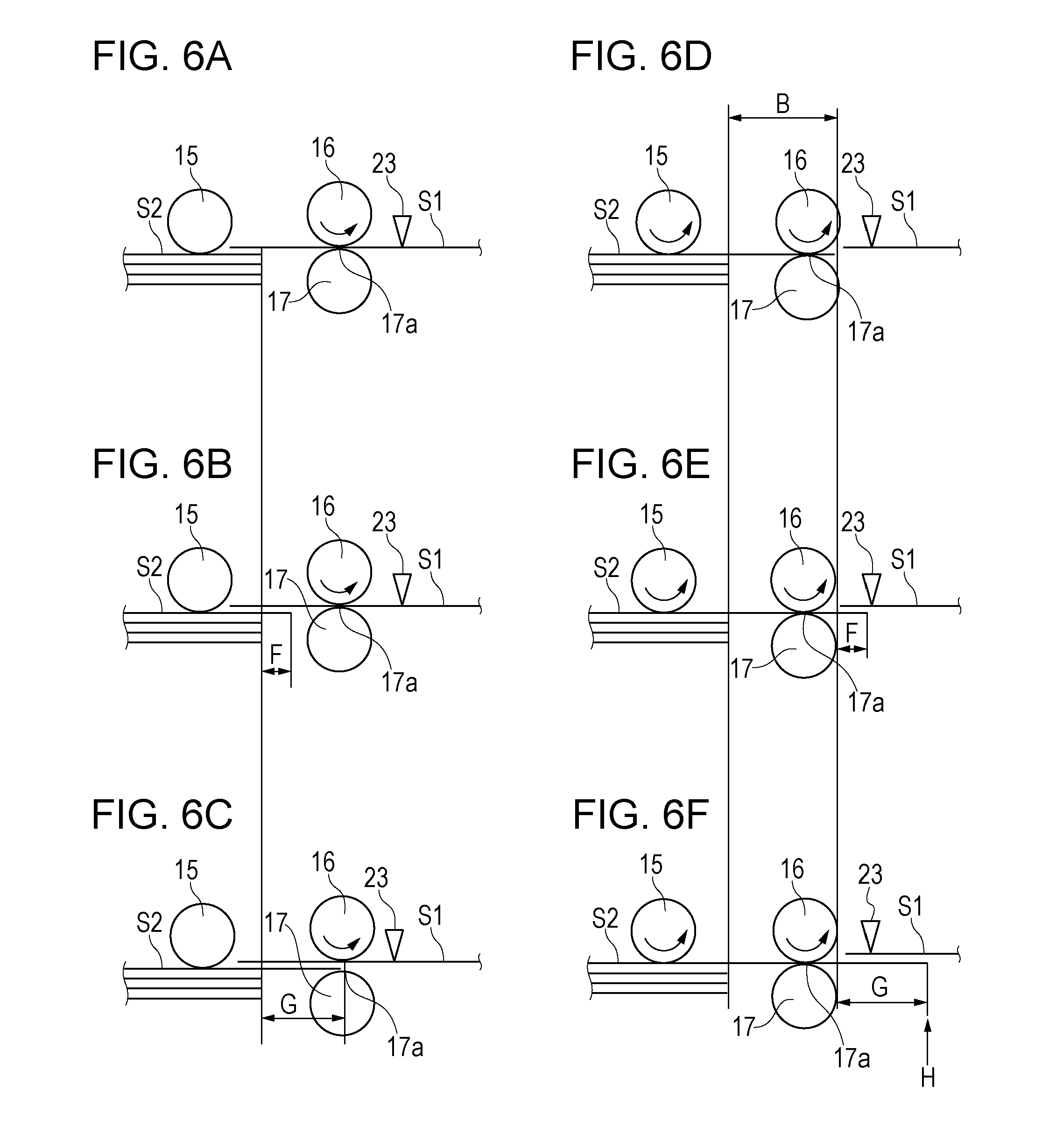
[0013] FIGS. 6A to 6F are views for explaining a motion of a sheet in Embodiment 1.
[0014] FIG. 7 is a view for explaining distribution of a position of a leading end of a sheet in Embodiment 1.
[0015] FIG. 8 is a graph for explaining a positional relation between a preceding sheet and a following sheet in a comparative example.
[0016] FIG. 9 is a graph for explaining a positional relation between a preceding sheet and a following sheet in Embodiment 1.
[0017] FIG. 10 is a view illustrating an example of an arrangement position of the conveyance sensor in Embodiment 1.
[0018] FIGS. 11A and 11B illustrate a flowchart of control at a time of sheet feeding in Embodiment 1.
[0019] FIG. 12 is a control block diagram of a printer in Embodiment 2.
[0020] FIG. 13 is a graph for explaining a positional relation between a preceding sheet and a following sheet in Embodiment 2.
[0021] FIGS. 14A and 14B illustrate a flowchart of control at a time of sheet feeding in Embodiment 2.
[0022] FIG. 15 is a graph for explaining a positional relation between a preceding sheet and a following sheet in Embodiment 3.
[0023] FIG. 16 illustrates a configuration of a conveyance sensor in a modification example 1.
[0024] FIG. 17 illustrates a configuration of a conveyance sensor in a modification example 2.
[0025] FIGS. 18A to 18C are views for explaining an issue in a related art.
DESCRIPTION OF THE EMBODIMENTS
Embodiment 1
<Configuration>
[0026] Embodiments will be described below with reference to drawings. Note that, the same reference signs are assigned to components common among the drawings.
[0027] FIG. 1 is a sectional view schematically illustrating a full-color laser beam printer 100 (hereinafter, referred to as a printer 100) as an example of an image forming apparatus that includes a feeding apparatus in Embodiment 1.
[0028] In FIG. 1, the printer 100 includes photosensitive drums 1, serving as image bearing members, in process cartridges 7. The process cartridges 7 are provided correspondingly to four colors in total of yellow (Y), magenta (M), cyan (C), and black (B). In FIG. 1, any one of reference signs (Y, M, C, K) that represent colors is added after a reference sign of a corresponding one of the members to thereby represent a member with a specific color. For example, a photosensitive drum for yellow is represented by 1Y. Hereinafter, when representing a member with a specific color is not required, each of the reference signs (Y, M, C, K) that represent colors is omitted. A charging roller (not illustrated) provided in each of the process cartridges 7 charges a surface of a corresponding one of the photosensitive drums 1. A laser scanner unit 2 radiates laser light L to each of the photosensitive drums 1 based on image information so that an electrostatic latent image is formed on the photosensitive drum 1. The latent image formed on the photosensitive drum 1 is visualized with toner by a development roller (not illustrated) which is provided in the process cartridge 7. In this manner, toner images of the respective colors that are formed on the photosensitive drums 1 are transferred on an intermediate transfer belt 9 by primary transfer rollers 5 while sequentially being superimposed. The intermediate transfer belt 9 is rotated by a driving roller 8 and a color toner image formed on the intermediate transfer belt 9 is transferred onto a sheet S by a secondary transfer belt 6. These process members function as image forming units configured to form an image on the sheet S.
[0029] The feeding apparatus is composed of a cassette 10 and a roller unit 19. In the cassette 10, a sheet stacking plate 22 that is a stacking portion on which a plurality of sheets S are stacked is provided. In a standby state, a sheet S is moved up to a drawn-out position by the sheet stacking plate 22 and a sheet (preceding sheet) S that is positioned at the uppermost position is in contact with a pickup roller 15 (hereinafter, referred to as a pick roller 15). When a print signal is input, the pick roller 15 (feeding member) feeds the sheet S1 among the sheets S stacked on the sheet stacking plate 22. A feed roller 16 (first conveyance member) further feeds the sheet S1 fed by the pick roller 15 toward a downstream side. A separation roller 17 (separation member) is fixed to a chassis or the like of the printer 100 via a torque limiter (not illustrated). An operation of the separation roller 17 will be described in detail later.
[0030] The sheet S1 fed by the feed roller 16 is conveyed by a pair of registration rollers 3 and 4 (second conveyance member). A conveyance sensor 23 and a top sensor 24 detect the sheet S1 that is conveyed. Onto the sheet S1 conveyed by the pair of the registration rollers 3 and 4, the toner image is transferred by the aforementioned secondary transfer roller 6. After that, a fixing unit 12 fixies the toner image, which is transferred onto the sheet S1, on the sheet S1 with heat and pressure. The sheet S1 on which the toner image is fixed is discharged to a sheet discharge try 13 by a pair of discharge rollers 11.
[0031] FIG. 2 illustrates a configuration of the conveyance sensor 23 in the present embodiment. In the present embodiment, the conveyance sensor 23 in which a rotation-type sensor arm 30 and a photo-interrupter 31 are combined is used. The sensor arm 30 is configured to be rotatable about a rotation shaft 34 as a center and an arm portion 30a enters a conveyance path of a sheet S. The arm portion 30a comes into contact with the sheet S that is conveyed, so that the sensor arm 30 is rotated by passage of the sheet S. When the sensor arm 30 is rotated, a sensor flag 30b that is integrally provided with the sensor arm 30 is also rotated so that a light transmitting state and a light shielding state of the photo-interrupter 31 are switched. By a signal output from the photo-interrupter 31, it is possible to detect presence or absence of the sheet S and a timing when a leading end or a rear end of the sheet S passes. Additionally, the top sensor 24 also has the same configuration as that of the conveyance sensor 23.
[0032] FIG. 3 is a perspective view illustrating appearance of the printer 100. The cassette 10 is configured to be pullable toward a front surface side of a main body of the apparatus. A user pulls out the cassette 10 and supplies a sheet S for the cassette 10. In addition, a door for jam processing 20 is configured on a side surface side of the main body of the apparatus to be openable/closable. When a sheet S remains in the middle of the conveyance path, that is, when a jam occurs, the user is able to remove the sheet S remaining inside by opening the door for jam processing 20. Additionally, an operation panel 29 is provided on the printer 100. The operation panel 29 provides guidance of each operation to the user through a liquid crystal screen. The operation panel 29 also displays an error or a button or an icon for performing a manual operation. For example, when a jam occurs, based on information of each sensor, it is determined at which part in the apparatus the jam occurs, and how to perform jam processing is notified to the user in an easy-to-understand manner through the operation panel 29. Note that, simple notification by, for example, an LED may be performed without the liquid crystal screen. For example, an LED may be arranged in each of the cassette 10 and the door for jam processing 20, and the LED to be accessed by the user for the jam processing may be turned on.
[0033] FIG. 4 is a control block diagram of the printer 100 in the present embodiment. An engine control unit 26 that controls an operation of the printer 100 includes a CPU, a ROM, a RAM, and the like therein and executes processing based on a program stored in the ROM in advance. In FIG. 4, for example, description related to a process other than a sheet feeding operation, such as an image forming process, is omitted. A motor 27 is connected to the engine control unit 26. The motor 27 drives and rotates the pick roller 15 and the feed roller 16 through an electromagnetic clutch 28. The electromagnetic clutch 28 transmits or intercepts driving force of the motor 27 with respect to the pick roller 15 or the feed roller 16. One-way clutches (not-illustrated) are built in the pick roller 15 and the feed roller 16, and when the electromagnetic clutch 28 is turned OFF, the pick roller 15 and the feed roller 16 are brought into a state of being rotatable only in a direction in which a sheet S is fed. Additionally, the motor 27 drives and rotates the pair of the registration rollers 3 and 4. It is configured that detection results of the conveyance sensor 23 and the top sensor 24 are notified to the engine control unit 26 to display information such as occurrence of a jam on the operation panel 29.
<Operation>
[0034] A sheet feeding operation of the present embodiment will be described in detail by using FIG. 5. FIG. 5 is a timing chart of control at a time of the sheet feeding and a view schematically illustrating a positional relation between a rear end of a sheet S1 that is being fed and each of the rollers. Here, the rear end of the sheet S1 indicates an end of the sheet S1 on an upstream side in the feeding direction.
[0035] When a print signal is input, the engine control unit 26 rotates the pair of the registration rollers 3 and 4 by the motor 27. Almost at the same time, the engine control unit 26 turns the electromagnetic clutch 28 ON to rotate the pick roller 15 and the feed roller 16 (at a timing when the rear end of the sheet S1 is at a position d in FIG. 5).
[0036] The sheet S1 drawn out by the pick roller 15 passes through a separation nip portion 17a formed by the feed roller 16 and the separation roller 17 and reaches the pair of the registration rollers 3 and 4. When a leading end of the sheet S1 reaches the top sensor 24 positioned immediately after the pair of the registration rollers 3 and 4, the engine control unit 26 turns the electromagnetic clutch 28 OFF. At this time, the rear end of the sheet S1 does not pass through the pick roller 15 (at a timing when the rear end of the sheet S1 is at a position e in FIG. 5).
[0037] The pair of the registration rollers 3 and 4 convey the sheet S1 toward the downstream side so that the sheet S1 is pulled out from the separation nip portion 17a. At this time, since the electromagnetic clutch 28 is turned OFF, the driving force from the motor 27 is not transmitted to the pick roller 15 and the feed roller 16. However, the two rollers are driven to rotate by following the conveyance of the sheet S1 by the one-way clutches (not-illustrated). Then, at a timing when a predetermined time has elapsed since the rear end of the sheet S1 had passed through the pick roller 15, the engine control unit 26 turns the electromagnetic clutch 28 ON again (at a timing when the rear end of the sheet S1 is at a position fin FIG. 5).
[0038] The electromagnetic clutch 28 is turned ON again and the pick roller 15 and the feed roller 16 are rotated. At this time, since the sheet S1 has already passed through the pick roller 15, a sheet (following sheet) S2 to be fed next after the sheet S1 is in contact with the pick roller 15 and is fed. This operation is expressed as "pre-feeding". Here, the sheet S1 and the sheet S2 are conveyed while being partially overlapped. Then, at a timing when the sheet S2 is conveyed by the pick roller 15 by a predetermined distance B illustrated in FIG. 5, the engine control unit 26 turns the electromagnetic clutch 28 OFF again. At this time, the sheet S1 is also conveyed by the feed roller 16 and the pair of the registration rollers 3 and 4 by a predetermined distance C (=B) illustrated in FIG. 5 (at a timing when the rear end of the sheet S1 is at a position g in FIG. 5). A purpose for performing such pre-feeding is to take a countermeasure against sound during conveyance of a sheet, and a content thereof will be described in detail later.
[0039] At a time point when a pre-feeding operation of the sheet S2 ends, the rear end of the sheet S1 has passed through the separation nip portion 17a. Although detailed description will be given later, at the time point when the pre-feeding operation of the sheet S2 ends, the leading end of the sheet S2 has passed through the separation nip portion 17a. But the leading end of the sheet S2 does not reach the pair of the registration rollers 3 and 4. Accordingly, the sheet S2 is stopped in a state where the electromagnetic clutch 28 is turned OFF. That is, the pick roller 15 and the feed roller 16 are not rotated by the sheet S2 and stop. The sheet S1 is conveyed toward a further downstream side by the pair of the registration rollers 3 and 4, and image formation is performed. As above, the sheet feeding operation of the sheet S1 ends.
[0040] The engine control unit 26 calculates a start timing (f in FIG. 5) of the pre-feeding operation or an end timing (g in FIG. 5) of the pre-feeding operation of the sheet S2 based on a timing when the sheet S1 reaches the top sensor 24. The engine control unit 26 calculates these timings by taking a length of the sheet S1 and a conveyance speed of the sheet S1 into consideration. A time lag of responsiveness of the electromagnetic clutch 28 or delay due to a space between driving columns (not illustrated) arises until the pick roller 15 rotates after the electromagnetic clutch 28 is turned ON, so that the engine control unit 26 calculates the timings also by taking the time lag or the delay into consideration.
[0041] Note that, the start timing or the end timing of the pre-feeding operation may be calculated based on a timing when the sheet S1 reaches the conveyance sensor 23 instead of the top sensor 24 or may be calculated based on a timing when feeding of the sheet S1 stacked on the cassette 10 is started by the pick roller 15 and the feed roller 16.
[0042] Moreover, when a plurality of sheets S are continuously fed, the motor 27 may be continuously rotated so that ON and OFF of the electromagnetic clutch 28 are repeatedly switched.
[0043] Here, before the pick roller 15 comes in contact with the following sheet S2, that is, before the pre-feeding of the following sheet S2 is performed, the sheet S2 is moved due to frictional force between the preceding sheet S1 and the following sheet S2 (hereinafter, expressed as "being dragged") in some cases. The sheet S2 may not be dragged at all, or may be dragged to a position before the separation nip portion 17a, or may be dragged to the separation nip portion 17a. Description of being dragged will be given below by using FIGS. 6A to 6F.
[0044] FIG. 6A illustrates a state where the sheet S2 is not dragged at all. FIG. 6B illustrates a state where the sheet S2 is separated from the sheet S1 at the position before the separation nip portion 17a and stopped after being slightly dragged. FIG. 6C illustrates a state where the sheet S2 is separated from the sheet S1 and stopped at the separation nip portion 17a after being completely dragged. In FIGS. 6A to 6C, the electromagnetic clutch 28 is turned OFF. In addition, the sheet S1 is conveyed by the pair of the registration rollers 3 and 4 (not illustrated in FIGS. 6A to 6F), and the feed roller 16 is driven to rotate by the sheet S1. The pick roller 15 that is in contact with the sheet S2 stops. A position of the leading end of the sheet S2 advances by a distance F in FIG. 6B and by a distance G in FIG. 6C when FIG. 6A is set as a reference.
[0045] In the present embodiment, "being dragged" indicates a phenomenon that the following sheet S2 is moved due to influence of the friction with the preceding sheet S1, that is, a phenomenon that the following sheet S2 is moved although the following sheet S2 and the pick roller 15 are not in contact with each other. Whereas, "pre-feeding" indicates an operation that the following sheet S2 is moved by a predetermined distance in advance by the pick roller 15 while a feeding operation of the preceding sheet S1 is performed. That is, in the pre-feeding, the following sheet S2 and the pick roller 15 are in contact with each other.
[0046] FIGS. 6D, 6E, and 6F indicate states where pre-feeding of the sheet S2 is completed after start of the pre-feeding from the states of FIGS. 6A, 6B, and 6C, respectively. In each of the states where the pre-feeding is completed, amounts of being dragged F and G are maintained as they are and the position of the leading end of the sheet S2 is moved by the predetermined distance B. As illustrated in FIGS. 6D, 6E and 6F, the leading end of the sheet S2 passes through the separation nip portion 17a in any cases.
[0047] Here, an operation of the separation roller 17 will be described. First, when there is no sheet S in the separation nip portion 17a, force received by the separation roller 17 due to friction with the feed roller 16 that is rotating is set to exceed a rotational load of the torque limiter. Thus, the separation roller 17 is rotated in a feeding direction of the sheet S. When one sheet S1 is conveyed to the separation nip portion 17a, force received by the separation roller 17 due to friction with the one sheet S1 is set to exceed the rotational load of the torque limiter. Thus, the separation roller 17 is rotated in the feeding direction of the sheet S1. When one sheet S1 is conveyed to the separation nip portion 17a and a sheet S2 is dragged due to influence of friction with the sheet S1, the rotational load of the torque limiter is set to exceed force received by the separation roller 17 due to friction with the two sheets S1 and S2. Thus, rotation of the separation roller 17 is stopped.
[0048] On the other hand, when the one sheet S1 is conveyed to the separation nip portion 17a and the sheet S2 is further conveyed by the pick roller 15, the force received by the separation roller 17 due to the friction with the two sheets S1 and S2 is set to exceed the rotational load of the torque limiter. Thus, the separation roller 17 is rotated in the feeding direction of the sheet S1. When the two sheets S1 and S2 are conveyed to the separation nip portion 17a and a sheet S3 is dragged due to influence of friction with the sheet S2, the rotational load of the torque limiter is set to exceed force received by the separation roller 17 due to friction with the three sheets S1 to S3. Thus, the rotation of the separation roller 17 is stopped.
[0049] A purpose of subjecting the sheet S2 to the pre-feeding after the rear end of the sheet S1 passes through the pick roller 15 is to reduce sound at a moment when the rear end of the sheet S1 passes through the separation nip portion 17a. The countermeasure against the sound will be described below in detail.
[0050] FIG. 7 illustrates distribution of a position of the leading end of the following sheet S2. Distribution of the position of the leading end of the sheet S2 in a case where the pre-feeding operation is not performed is illustrated in (a) of FIG. 7. The distribution of the position of the leading end of the sheet S2 has two peaks at a position j of setting in the cassette 10 and a position m of the separation nip portion 17a, and frequency thereof is high. Then, frequency at which the leading end of the sheet S2 is positioned within a range k therebetween is low. In a case of a paper type which is difficult to be dragged, the sheet S2 is hardly moved due to the influence of the friction with the sheet S1. On the other hand, in a case of a paper type which is easy to be dragged, the sheet S2 is moved due to the influence of the friction with the sheet S1, separated from the sheet S1 by the separation nip portion 17a, and stopped. Thereby, distribution of the position of the leading end of the sheet S2 has peaks at two positions.
[0051] As described in FIG. 18B, in a case where, when the rear end of the sheet S1 being fed passes through the separation nip portion 17a, the leading position of the following sheet S2 is at the position m of the separation nip portion 17a, the rear end of the sheet S1 being fed bounces due to a step caused by a thickness of the following sheet S2 and sudden sound is generated. In a case where the pre-feeding operation is not performed, since frequency at which the leading end of the following sheet S2 exists at the position m of the separation nip portion 17a is high, frequency at which the sudden sound is generated when the rear end of the sheet S1 being fed passes through the separation nip portion 17a is also high.
[0052] Distribution of the position of the leading end of the sheet S2 in a case where the pre-feeding operation is performed is illustrated in (b) of FIG. 7. The distribution of the position of the leading end of the sheet S2 is shifted to a position advanced by the predetermined distance B to the downstream side of the feeding direction as a whole compared to (a) of FIG. 7 in the case where the pre-feeding operation is not performed. In the present embodiment, the predetermined distance B by which the sheet S2 is moved by the pre-feeding operation is set to be longer than a distance A from the position j at which a leading end of a sheet S is set in the cassette 10 to the position m of the separation nip portion 17a. Thus, peaks of the position of the leading end of the sheet S2 are shifted to a position n and a position o that are on the downstream side of the separation nip portion 17a. Then, since frequency at which the leading end of the sheet S2 exists at the position m of the separation nip portion 17a is low (range p), frequency at which the sudden sound is generated when the rear end of the sheet S1 being fed passes through the separation nip portion 17a is low. That is, the sudden sound is able to be reduced.
[0053] When the leading end of the following sheet S2 reaches the pair of the registration rollers 3 and 4 by the pre-feeding operation, the following sheet S2 is conveyed while being overlapped with the sheet S1 being fed. In order to prevent this, the predetermined distance B by which the sheet S2 is conveyed by the pre-feeding operation is set to be shorter than a distance D from the separation nip portion 17a to the pair of the registration rollers 3 and 4. That is, this may be addressed by satisfying a relation of distance A<distance B<distance D.
[0054] Next, a timing when feeding of the following sheet S2 is started again after the pre-feeding is completed will be described. In order to enhance productivity of continuous printing, a sheet interval (interval between the rear end of the preceding sheet S1 and the leading end of the following sheet S2) may be made as short as possible. The sheet interval is set in advance in accordance with a size or a paper type of a sheet S. At a time point when the pre-feeding is completed, as illustrated in FIGS. 6D, 6E, and 6F, there is a possibility that the position of the leading end of the sheet S2 varies. The variation should be considered on deciding a feeding timing of the following sheet S2.
[0055] First, the feeding timing of the following sheet S2 in a comparative example will be described by using FIG. 8. A graph of a thick solid line indicates the position of the rear end of the sheet S1 and a graph of a thin solid line indicates the position of the leading end of the sheet S2. A case where the position of the leading end of the sheet S2 is most advanced (FIG. 6F) and a case where the position of the leading end of the sheet S2 is most delayed (FIG. 6D) are drawn by two lines, positions of the leading end of the sheet S2 are all distributed between the aforementioned two lines. As illustrated in FIG. 8, when the sheet S2 is most advanced, a sheet interval between the sheet S1 and the sheet S2 is the same as a set sheet interval, and when the sheet S2 is most delayed, the sheet interval is a sheet interval obtained by adding the distance G to the set sheet interval. Note that, as illustrated in FIG. 6C, the distance G is a distance from an initial position of a leading end of a sheet S stacked on the cassette 10 to the separation nip portion 17a.
[0056] Here, in FIG. 8, since the leading end of the sheet S2 in the state of FIG. 6F is advanced to the most downstream side, response delay of the electromagnetic clutch 28 or delay due to a space between gears or a backlash thereof is estimated based on the state and the feeding timing of the sheet S2 is set. As a method of setting the timing, for example, a method of obtaining a timing T3 when a predetermined time has elapsed since a timing when the leading end of the sheet S1 had been detected by the top sensor 24 is taken. Note that, the sheet feeding timing may be obtained based on the conveyance sensor 23 instead of the top sensor 24.
[0057] Next, the feeding timing of the following sheet S2 in the present embodiment will be described by using FIG. 9. In the present embodiment, in a case where the conveyance sensor 23 does not detect the stopped sheet S2, after the pre-feeding is completed, the feeding of the sheet S2 is started at a timing T4 that is earlier than the timing T3 illustrated in FIG. 8 so that the sheet interval is shortened. The timing T4 is calculated from a conveyance speed, a position of the conveyance sensor 23, or the like. Here, it is most effective in a case where a position of the conveyance sensor 23 is set on the upstream side by a distance G/2 from a position H (FIG. 6F) in a case where the sheet S2 is most advanced after the pre-feeding (after the electromagnetic clutch 28 is turned OFF). A configuration thereof is indicated in FIG. 10. In the case where the conveyance sensor 23 does not detect the stopped sheet S2 after the pre-feeding is completed, that is, in a case where the leading end of the sheet S2 is stopped on the upstream side from the conveyance sensor 23, a timing when the electromagnetic clutch 28 is turned ON is uniformly made earlier as illustrated in FIG. 9. Thereby, even in a case where the sheet S2 is most delayed, the sheet interval between the sheet S1 and the sheet S2 is a sheet interval obtained by adding the distance G/2 to the set sheet interval, so that variation in the sheet interval is refined by at most G/2 compared to that in the comparative example.
[0058] As described above, according to the present embodiment, a variation amount between a minimum sheet interval and a maximum sheet interval is able to be reduced by G/2 unless restriction of a configuration of the apparatus or the minimum sheet interval to be set is taken into consideration.
[0059] FIGS. 11A and 11B illustrate a flowchart in which the sheet feeding operation in the present embodiment is summarized. The engine control unit 26 executes control based on the flowchart in FIGS. 11A and 11B based on a program stored in a ROM or the like.
[0060] First, on reception of a print instruction, the engine control unit 26 determines whether or not a feeding timing of a sheet S from the cassette 10 arrives (S400). When determining that the feeding timing of the sheet S arrives, the engine control unit 26 starts a feeding operation of a sheet S1 (S401). Specifically, as described above, the engine control unit 26 causes the motor 27 to drive so that the electromagnetic clutch 28 is turned ON. Thereby, the pick roller 15, the feed roller 16, and the pair of the registration rollers 3 and 4 are rotated.
[0061] Next, the engine control unit 26 determines whether or not the conveyance sensor 23 or the top sensor 24 detects the sheet S1 (S402, S403). When determining that the top sensor 24 detects a leading end of the sheet S1, the engine control unit 26 turns the electromagnetic clutch 28 OFF (S404). Thereby, the sheet S1 is conveyed by the pair of the registration rollers 3 and 4, so that the pick roller 15 and the feed roller 16 are driven by conveyance of the sheet S1. Here, when the engine control unit 26 determines that the sheet S1 being fed is a final sheet of a print job (S405), the engine control unit 26 stops the motor 27 after the feeding of the sheet S1 (S413) and ends the sheet feeding operation. On the other hand, when the engine control unit 26 determines that the sheet S1 is not the final sheet, the engine control unit 26 proceeds to processing at S406.
[0062] When the sheet S1 is not the final sheet, that is, a next sheet S2 is continuously fed, the engine control unit 26 obtains at least a timing when a rear end of the sheet S1 has passed through the pick roller 15. In the present embodiment, the engine control unit 26 determines whether or not a timing when a predetermined time T1 has elapsed since the top sensor 24 had detected the leading end of the sheet S1 arrives (S406). In a case where determining that the timing when the predetermined time T1 has elapsed arrives, the engine control unit 26 turns the electromagnetic clutch 28 ON to start a pre-feeding operation of the sheet S2 (S407).
[0063] Next, the engine control unit 26 determines whether or not a timing when the sheet S2 is conveyed by the predetermined distance B, that is, a timing when a predetermined time T2 has elapsed since the top sensor 24 had detected the leading end of the sheet S1 arrives (S408). In a case of determining that the timing when the predetermined time T2 has elapsed arrives, the engine control unit 26 turns the electromagnetic clutch 28 OFF to end the pre-feeding operation of the sheet S2 (S409).
[0064] As already described by using FIGS. 6A to 6F or FIG. 7, the position of the leading end of the sheet S2 at a time point when the pre-feeding operation of the sheet S2 ends and the feeding of the sheet S2 is started again varies within the range of the distance G. The conveyance sensor 23 is arranged within the range of the variation and detects presence or absence of the stopped sheet S2 (S410). In the case where the conveyance sensor 23 detects the sheet S2, the leading end of the sheet S2 is on the downstream side from the conveyance sensor 23, and in the case where the conveyance sensor 23 does not detect the sheet S2, the leading end of the sheet S2 is on the upstream side from the conveyance sensor 23. Then, in the case where the conveyance sensor 23 detects the sheet S2, the engine control unit 26 turns the electromagnetic clutch 28 ON at the timing T3 when a predetermined time has elapsed since the top sensor 24 had detected the leading end of the sheet S1 (S411). Additionally, in the case where the conveyance sensor 23 does not detect the sheet S2, the engine control unit 26 turns the electromagnetic clutch 28 ON at the timing T4 when a predetermined time has elapsed since the top sensor 24 had detected the leading end of the sheet S1 (S412). Here, the timing T4 is earlier than the timing T3 and is a timing for reducing a variation amount to at most 1/2. In this manner, when the leading end of the sheet S2 is on the upstream side from the conveyance sensor 23, by setting a sheet feeding start timing earlier compared to a case where the leading end of the sheet S2 is on the downstream side, it is possible to shorten the sheet interval between the sheet S1 and the sheet S2 compared to a case where sheet feeding is always started at a fixed timing.
[0065] Note that, processing at 410 by which the conveyance sensor 23 detects presence or absence of the sheet S2 is executed at a timing after a time required for the rear end of the sheet S1 to pass through the conveyance sensor 23 has elapsed at least. A start point at which the engine control unit 26 counts the time may be a timing when the conveyance sensor 23 detects the leading end of the sheet S1 or may be a timing when the top sensor 24 detects the leading end of the sheet S1.
[0066] Next, a method of specifying a jam position by using the conveyance sensor 23 will be described. When determining, at S402, that the conveyance sensor 23 does not detect the sheet S1, the engine control unit 26 determines whether or not a threshold time Tth1 has elapsed since the feeding operation of the sheet S1 had been started (S414). Here, the threshold time Tth1 is longer than at least the predetermine time T1. In a case of determining that a timing when the threshold time Tth1 has elapsed arrives, the engine control unit 26 displays, on the operation panel 29 provided on the printer 100, a message indicating that a jam occurs. Furthermore, it is determined that the leading end of the sheet S1 has not reached the conveyance sensor 23 (not passed through the separation nip portion 17a), and display is performed on the operation panel 29 to urge pulling out the cassette 10 to perform jam processing (S415).
[0067] When determining, at S403, that the top sensor 24 does not detect the sheet S1, the engine control unit 26 determines whether or not a timing when a threshold time Tth2 has elapsed since the conveyance sensor 23 had detected the sheet S1 arrives (S416). In a case where determining that the timing when the threshold time Tth2 has elapsed arrives, the engine control unit 26 displays, on the operation panel 29 provided on the printer 100, a message indicating that a jam occurs. At this time, it is determined that the leading end of the sheet S1 has passed through the conveyance sensor 23 and stopped at a position not reaching the top sensor 24, and display is performed on the operation panel 29 to urge opening the door for jam processing 20 to perform jam processing (S417).
[0068] Since a conventional apparatus does not include the conveyance sensor 23 as in the present embodiment, it is difficult to determine whether a leading end of a jammed sheet that does not reach the top sensor 24 remains in the cassette 10 or stops in a conveyance path on the upstream side of the top sensor 24. Thus, there is a case where it is difficult for a user to find the jammed sheet by opening the door for jam processing 20 in a state where the jammed sheet remains in the cassette 10 or the jammed sheet is torn out because the cassette 10 is pulled out with the jammed sheet positioned over the cassette 10 and the conveyance path. According to the configuration in the present embodiment, it is possible to guide an appropriate method of jam processing by accurately detecting a jam position without adding a new sensor for detecting a jam. Then, control of the flowchart ends.
[0069] As above, according to the present embodiment, it is possible to provide an image forming apparatus and a feeding apparatus whose productivity is refined while reducing sudden sound when a rear end of a recording material passes through a separation nip portion.
Embodiment 2
[0070] Next, Embodiment 2 will be described. In Embodiment 2, a difference from Embodiment 1 will be mainly described and description of components similar to those of Embodiment 1 will be omitted.
<Configuration>
[0071] In Embodiment 1, the motor 27 drives the pair of the registration rollers 3 and 4, the pickup roller 15, and the feed roller 16. On the other hand, as illustrated in a block diagram of FIG. 12, a motor 37 drives the pair of the registration rollers 3 and 4, and a motor 36 drives the pickup roller 15 and the feed roller 16 in the present embodiment. Thus, no electromagnetic clutch is required, and the motor 36 is caused to rotate or stop in the present embodiment instead of the operation of turning the electromagnetic clutch 28 ON or OFF in Embodiment 1. Note that, the motor 37 may also serve as drive of the photosensitive drum 1 or the like. Other configurations are similar to those in Embodiment 1.
<Operation>
[0072] The pre-feeding operation of the sheet S2 is similar to that of Embodiment 1 except for a difference of the electromagnetic clutch and the motor described above. In Embodiment 1, after the pre-feeding ends, "timing" at which feeding of the sheet S is started is changed by changing a timing when the electromagnetic clutch 28 is turned ON in accordance with a detection result by the conveyance sensor 23, but in the present embodiment, a "conveyance speed" of the sheet S2 is changed.
[0073] An operation of the present embodiment will be described by using a graph of FIG. 13. In FIG. 13, a graph of a thick solid line indicates the position of the rear end of the sheet S1 and three graphs of thin solid lines each indicate the position of the leading end of the sheet S2. The three graphs indicate a case where the position of the leading end of the sheet S2 is most advanced, a case where the position of the leading end of the sheet S2 is at a middle position, and a case where the position of the leading end of the sheet S2 is most delayed. In the case where the leading end of the sheet S2 is most advanced, the sheet interval between the sheet S1 and the sheet S2 becomes the set sheet interval, so that no special operation is performed. At this time, a timing when the leading end of the sheet S2 reaches the pair of the registration rollers 3 and 4 is set as T5. Next, in the case where the position of the leading end of the sheet S2 is at the middle position, specifically, when the motor 36 stops, the leading end of the sheet S2 is at a position immediately before the conveyance sensor 23 on the upstream side. That is, in this case, the conveyance sensor 23 does not detect the stopped sheet S2. Here, the motor 36 starts rotating at the timing T3 and the motor 36 is driven so that a conveyance speed of the sheet S2 by the pick roller 15 and the feed roller 16 is faster than a conveyance speed of the sheet S1 by the pair of the registration rollers 3 and 4. Thereby, the leading end of the sheet S2 is to reach the pair of the registration rollers 3 and 4 at the timing T5. Note that, in a case where the conveyance speed is not changed, a timing when the leading end of the sheet S2 reaches the pair of the registration rollers 3 and 4 is T7, so that delay occurs. When the position of the leading end of the sheet S2 is most delayed, since the conveyance speed is made faster in the same manner as above, a timing when the leading end of the sheet S2 reaches the pair of the registration rollers 3 and 4 is T6. Note that, in a case where the conveyance speed is not changed, a timing when the leading end of the sheet S2 reaches the pair of the registration rollers 3 and 4 is T8, so that delay occurs. By the aforementioned operation, the sheet interval between the sheet S1 and the sheet S2 is able to be reduced also in the present embodiment.
[0074] FIGS. 14A and 14B illustrate a flowchart of the present embodiment. Processing of S500 to S510 and S514 to S517, which is described in FIGS. 14A and 14B, is basically the same as the processing of S400 to S410 and S414 to S417, which is described in FIGS. 1A and 11B. In the processing, processing of rotating/stopping the motor 36 at S504, S507, or S509 is one obtained by replacing processing of turning the electromagnetic clutch 28 ON/OFF at S404, S407, or S409, respectively. A difference from the flowchart described in FIGS. 11A and 11B lies at S518 and S519. In a case where the conveyance sensor 23 detects the sheet S2 at a feeding start timing of the sheet S2, the engine control unit 26 rotates the motor 36 so that the sheet S2 is conveyed at a normal conveyance speed V1 (S518). On the other hand, in a case where the conveyance sensor 23 does not detect the sheet S2, the engine control unit 26 rotates the motor 36 so that the sheet S2 is conveyed at a conveyance speed V2 that is faster than the conveyance speed V1 (S519).
[0075] In Embodiment 1, the timing when the sheet S2 reaches the pair of the registration rollers 3 and 4 is made earlier by setting the feeding start timing of the sheet S2 to be earlier. In the present embodiment, the timing when the sheet S2 reaches the pair of the registration rollers 3 and 4 is made earlier by increasing a speed at which the sheet S2 is conveyed. The present embodiment is effective in a case where a sheet interval that is set in advance is very short and it is therefore difficult to set the feeding start timing of the sheet S2 to be earlier, for example.
[0076] As above, according to the present embodiment, it is possible to provide an image forming apparatus and a feeding apparatus whose productivity is refined while reducing sudden sound when a rear end of a recording material passes through a separation nip portion.
Embodiment 3
[0077] Next, Embodiment 3 will be described. In Embodiment 3, a difference from Embodiment 1 and Embodiment 2 will be mainly described and description of components similar to those of Embodiment 1 or Embodiment 2 will be omitted.
<Configuration>
[0078] A configuration of Embodiment 3 is similar to that of Embodiment 2.
<Operation>
[0079] The pre-feeding operation of the sheet S2 is similar to that of Embodiment 2. In the present embodiment, the conveyance speed of the sheet S2 is changed while changing the feeding start timing of the sheet S2 depending on a detection result by the conveyance sensor 23. Additionally, a difference lies in that, although the conveyance speed of the sheet S2 is increased in Embodiment 2, the conveyance speed of the sheet S2 is reduced in the present embodiment.
[0080] An operation of the present embodiment will be described by using a graph of FIG. 15. In FIG. 15, a graph of a thick solid line indicates the position of the rear end of the sheet S1 and three graphs of thin solid lines each indicate the position of the leading end of the sheet S2. The three graphs indicate a case where the position of the leading end of the sheet S2 is most advanced, a case where the position of the leading end of the sheet S2 is at a middle position, and a case where the position of the leading end of the sheet S2 is most delayed. A graph of a broken line indicates an operation before the control of the present embodiment is applied. Before the application of the control of the present embodiment, timings when the leading end of the sheet S2 reaches the pair of the registration rollers 3 and 4 in the respective cases are T5, T7, and T8, and there is variation of T8 to T5 at maximum. Note that, a graph indicated as the middle of the variation indicates a case where the leading end of the sheet S2 is at the position immediately before the conveyance sensor 23 on the upstream side, specifically, when the motor 36 is stopped. That is, in this case, the conveyance sensor 23 does not detect the stopped sheet S2.
[0081] In the present embodiment, in a case where the conveyance sensor 23 does not detect the sheet S2 when the motor 36 is caused to stop, the feeding start timing of the sheet S2 is changed from T3 to T9. Here, T9 is a timing when a timing when the leading end of the sheet S2 in a case of being most delayed reaches the pair of the registration rollers 3 and 4 is just at T5. On the other hand, also in the case where the leading end of the sheet S2 is at the middle position, the feeding start timing of the sheet S2 is changed to T9. In this case, the timing of reaching the pair of the registration rollers 3 and 4 is made earlier from T7 to T11 as illustrated by a two-dot chain line in FIG. 15. Then, the leading end of the sheet S2 reaches the pair of the registration rollers 3 and 4 at a timing earlier than the set sheet interval, so that there is a possibility that inconvenience, such as a sheet interval being too short to perform image forming in time, occurs. Therefore, a rotation speed of the motor 36 is set to be slow by a predetermined amount calculated from time until the conveyance sensor 23 detects the leading end of the sheet S2 after starting feeding of the sheet S2. Thereby, the leading end of the sheet S2 is to reach the pair of the registration rollers 3 and 4 at the timing T5.
[0082] Note that, adjustment of the sheet interval is to be completed before the leading end of the sheet S2 reaches the pair of the registration rollers 3 and 4 here, but the adjustment of the sheet interval may be completed before the leading end of the sheet S2 reaches the secondary transfer roller 6 at the latest. In this case, a speed of the pair of the registration rollers 3 and 4 also may be set to be variable.
[0083] By the aforementioned operation, the timing when the leading end of the sheet S2 reaches the pair of the registration rollers 3 and 4 is able to be uniformized to be T5. The configuration of the present embodiment makes it possible to minimize or eliminate variation in the sheet interval and is able to be used even when the conveyance speed is not able to be made faster because of an issue, for example, such as a rated performance of the motor 36 or operation sound thereof.
[0084] As above, according to the present embodiment, it is possible to provide an image forming apparatus and a feeding apparatus whose productivity is refined while reducing sudden sound when a rear end of a recording material passes through a separation nip portion.
Modification Example 1
[0085] Description has been given by using the sensor having the configuration described in FIG. 2 as the conveyance sensor 23 in Embodiment 1 to Embodiment 3 described above. However, there is no limitation thereto. As illustrated in FIG. 16, a type that detects a rotation angle of the sensor arm 30 in detail by providing a rotary encoder wheel 32 on a rotation shaft 34 may be used.
[0086] In FIG. 16, the sensor arm 30 is configured to be rotatable about the rotation shaft 34 as a center and the arm portion 30a enters an inside of a conveyance path of a sheet S. The arm portion 30a is in contact with the sheet S that is conveyed so that the sensor arm 30 is rotated by passage of the sheet S. As the sensor arm 30 is rotated, the rotary encoder wheel 32 that is integrally formed with the sensor arm 30 is also rotated. A wheel detecting unit 33 is able to detect the rotation angle of the sensor arm 30 based on a rotational amount of the rotary encoder wheel 32. In a case where a conveyance sensor 35 detects the sheet S2, the rotation angle of the sensor arm 30 becomes larger as a stop position of the sheet S is at a position further on the downstream side. That is, according to the conveyance sensor 35 that has the configuration of FIG. 16, it is possible to detect the position of the leading end of the sheet S2 more in detail compared to the conveyance sensor 23 that has the configuration described in FIG. 2.
[0087] After the pre-feeding operation of the following sheet S2 is completed, and the sheet S1 is conveyed by the pair of the registration rollers 3 and 4, and the sheet 1 and the sheet 2 that are partially overlapped are separated from each other, the engine control unit 26 determines whether or not the conveyance sensor 35 detects the sheet S2. In the case where the conveyance sensor 35 detects the sheet S2, the engine control unit 26 further obtains the position of the leading end of the sheet S2 based on the rotation angle of the sensor arm 30. Then, the engine control unit 26 changes a feeding condition such as the feeding start timing of the sheet S2 or the feeding speed thereof in accordance with the obtained position of the leading end of the sheet S2.
Modification Example 2
[0088] Description has been given by using the sensor having the configuration described in FIG. 2 as the conveyance sensor 23 in Embodiment 1 to Embodiment 3 described above. However, there is no limitation thereto. As illustrated in FIG. 17, even when the preceding sheet S1 and the following sheet S2 are overlapped, the leading end of the following sheet S2 may be detected by using an ultrasonic wave sensor 40.
[0089] In FIG. 17, the ultrasonic wave sensor 40 includes a transmission unit 38 that transmits an ultrasonic wave and a reception unit 39 that receives the ultrasonic wave transmitted from the transmission unit 38. The transmission unit 38 and the reception unit 39 are disposed to hold a conveyance path of a sheet S therebetween and the reception unit 39 receives the ultrasonic wave that is attenuated through the sheet S. Here, by an amplitude value of the ultrasonic wave received by the reception unit 39, whether or not the sheet S exists between the transmission unit 38 and the reception unit 39 or how many sheets S exist therebetween when the sheet S exists is able to be detected. That is, as illustrated in FIG. 17, even in a state where the preceding sheet S1 and the following sheet S2 are conveyed while the rear end of the preceding sheet S1 and the leading end of the following sheet S2 are overlapped, it is possible to detect a timing when the leading end of the following sheet S2 passes between the transmission unit 38 and the reception unit 39. The ultrasonic wave sensor 40 is disposed between the separation nip portion 17a and the pair of the registration rollers 3 and 4.
[0090] After the pre-feeding operation is completed and the electromagnetic clutch 28 is turned OFF or the motor 36 is caused to stop, an ON timing of the electromagnetic clutch 28 or a conveyance speed by the motor 36 is changed depending on whether or not the conveyance sensor 23 detects the sheet S2, in Embodiment 1 to Embodiment 3. In the present embodiment, the position of the leading end of the sheet S2 is able to be determined even in a state where the sheet S1 and the sheet S2 are overlapped. Thus, the engine control unit 26 obtains the position of the leading end of the sheet S2 from a timing when the ultrasonic wave sensor 40 detects the leading end of the sheet S2 during the pre-feeding and a timing when the electromagnetic clutch 28 is turned OFF or the motor 36 is caused to stop so that the sheet S2 is temporarily stopped. Then, the engine control unit 26 changes a feeding condition such as the feeding start timing of the sheet S2 or the feeding speed thereof in accordance with the obtained position of the leading end of the sheet S2.
[0091] In this manner, according to the configuration of the modification example, the position of the leading end of the sheet S2 is determined more accurately, so that it is possible to reduce variation in the sheet interval between the sheet S1 and the sheet S2 by finely controlling the feeding start timing of the sheet S2 or the feeding speed thereof.
[0092] As illustrated in FIG. 5, in the pre-feeding operation in Embodiment 1 to Embodiment 3 described above, the electromagnetic clutch 28 is turned OFF or the motor 36 is caused to stop for a while before the rear end of the preceding sheet S1 passes through the pick roller 15. Then, the electromagnetic clutch 28 is turned ON or the motor 36 is caused to rotate again after the rear end of the preceding sheet S1 passes through the pick roller 15. However, there is no limitation thereto. The pick roller 15 and the feed roller 16 may be continuously rotated to perform the pre-feeding operation, without turning the electromagnetic clutch 28 OFF or stopping the motor 36.
[0093] By continuously rotating the pick roller 15 and the feed roller 16, for example, an effect that influence of backward tension caused by turning the electromagnetic clutch 28 OFF is able to be suppressed is obtained, resulting in that the conveyance speed of the sheet S1 by the pair of the registration rollers 3 and 4 is stabilized. The electromagnetic clutch 28 is not turned OFF during a time when the pick roller 15 and the feed roller 16 are in contact with the sheet S1, so that states of the pick roller 15 and the feed roller 16 are not shifted into driven states. Thus, it is possible to prevent the conveyance speed of the sheet S1 from changing due to occurrence of backward tension caused by influence of the pick roller 15 and the feed roller 16.
[0094] Also in a case of executing control of Embodiment 1 described above, the configuration of Embodiment 2 (Embodiment 3) may be adopted. That is, the electromagnetic clutch 28 may not be arranged but the motor 36 and the motor 37 may be arranged.
[0095] Additionally, in Embodiment 1 to Embodiment 3 described above, the separation roller 17 is used for separating one sheet S from a plurality of sheets S, but there is no limitation thereto. A retard roller by which one sheet S is separated from a plurality of sheets S by rotating in a direction opposite to the feeding direction of the sheet S may be used.
[0096] Additionally, in Embodiment 1 to Embodiment 3 described above, the description has been given by using a feeding apparatus that is provided in the printer 100 in a fixed manner. But there is no limitation thereto. The disclosure may be applied to an optional sheet feeding apparatus that is detachably attachable to the printer 100. The optional sheet feeding apparatus includes a control unit and has a configuration similar to the block diagram described in FIG. 4. It may be configured that the optional sheet feeding apparatus is not mounted with the control unit, and the engine control unit 26 of a side of the printer 100 performs control of each roller provided in the optional sheet feeding apparatus.
[0097] While the present disclosure has been described with reference to embodiments, it is to be understood that the disclosure is not limited to the disclosed embodiments. The scope of the following claims is to be accorded the broadest interpretation to encompass all such modifications and equivalent structures and functions.
[0098] This application claims the benefit of Japanese Patent Application No. 2017-207963 filed Oct. 27, 2017, which is hereby incorporated by reference herein in its entirety.
* * * * *
D00000
D00001
D00002
D00003
D00004
D00005
D00006
D00007
D00008
D00009
D00010
D00011
D00012

D00013

D00014

D00015

D00016

D00017

D00018

D00019

D00020

XML
uspto.report is an independent third-party trademark research tool that is not affiliated, endorsed, or sponsored by the United States Patent and Trademark Office (USPTO) or any other governmental organization. The information provided by uspto.report is based on publicly available data at the time of writing and is intended for informational purposes only.
While we strive to provide accurate and up-to-date information, we do not guarantee the accuracy, completeness, reliability, or suitability of the information displayed on this site. The use of this site is at your own risk. Any reliance you place on such information is therefore strictly at your own risk.
All official trademark data, including owner information, should be verified by visiting the official USPTO website at www.uspto.gov. This site is not intended to replace professional legal advice and should not be used as a substitute for consulting with a legal professional who is knowledgeable about trademark law.