Pallet And Pallet Cap
Hassell; Jon P. ; et al.
U.S. patent application number 15/978336 was filed with the patent office on 2019-05-02 for pallet and pallet cap. The applicant listed for this patent is Rehrig Pacific Company. Invention is credited to Derek Gravitt, Jon P. Hassell, Mariel Rezende.
| Application Number | 20190127115 15/978336 |
| Document ID | / |
| Family ID | 64268692 |
| Filed Date | 2019-05-02 |


View All Diagrams
| United States Patent Application | 20190127115 |
| Kind Code | A1 |
| Hassell; Jon P. ; et al. | May 2, 2019 |
PALLET AND PALLET CAP
Abstract
A pallet cap includes a plurality of raised surfaces and a plurality of parallel channels separating the plurality of raised surfaces. The pallet cap is securable to an upper surface of a deck of a pallet. The plurality of raised surfaces may include a central raised area, and the plurality of parallel channels may include a pair of inner channels, such that the central raised area is between the pair of inner channels. The pair of inner channels and the central raised area may be between an outer ridge and an inner ridge. The inner ridge and the outer ridge may project upward higher than the pair of inner channels.
| Inventors: | Hassell; Jon P.; (Atlanta, GA) ; Rezende; Mariel; (Potomac, MD) ; Gravitt; Derek; (Buford, GA) | ||||||||||
| Applicant: |
|
||||||||||
|---|---|---|---|---|---|---|---|---|---|---|---|
| Family ID: | 64268692 | ||||||||||
| Appl. No.: | 15/978336 | ||||||||||
| Filed: | May 14, 2018 |
Related U.S. Patent Documents
| Application Number | Filing Date | Patent Number | ||
|---|---|---|---|---|
| 62505816 | May 12, 2017 | |||
| Current U.S. Class: | 1/1 |
| Current CPC Class: | B65D 19/44 20130101; B65D 2519/00318 20130101; B65D 21/0212 20130101; B65D 2519/00288 20130101; B65D 2519/0099 20130101; B65D 19/0093 20130101; B65D 85/36 20130101; B65D 2519/00273 20130101; B65D 2519/00323 20130101; B65D 2519/00567 20130101; B65D 2519/00572 20130101; B65D 2519/00412 20130101; B65D 1/34 20130101; B65D 2519/00562 20130101; B65D 2519/00069 20130101; B65D 2519/00815 20130101; B65D 2519/00293 20130101; B65D 2519/00407 20130101; B65D 2519/00034 20130101; B65D 19/0085 20130101; B65D 2519/00333 20130101 |
| International Class: | B65D 19/00 20060101 B65D019/00 |
Claims
1. A pallet cap comprising: a plurality of raised surfaces; and a plurality of parallel channels separating the plurality of raised surfaces.
2. The pallet cap of claim 1 wherein the pallet cap is securable to an upper surface of a deck of a pallet.
3. The pallet cap of claim 2 wherein the pallet cap is thermoformed.
4. The pallet cap of claim 1 wherein the plurality of raised surfaces includes a central raised area, the plurality of parallel channels including a pair of inner channels, the central raised area between the pair of inner channels.
5. The pallet cap of claim 4 wherein the plurality of raised surfaces includes an outer ridge and an inner ridge, the pair of inner channels and the central raised area between the outer ridge and the inner ridge.
6. The pallet cap of claim 5 wherein the inner ridge and the outer ridge project upward higher than the pair of inner channels.
7. The pallet cap of claim 6 wherein the plurality of raised surfaces and plurality of channels include a first row and a second row, wherein each of the first row and the second row includes the central raised area, the pair of inner channels, the inner ridge, and the outer ridge.
8. The pallet cap of claim 7 in combination with a pallet having a deck and a plurality of columns supporting the deck, the pallet cap secured to the deck.
9. The combination of claim 8 further in combination with a first tray, the first tray including a base, a pair of opposed side walls, a front wall and a rear wall, wherein the front wall is shorter than the side walls, the base including a pair of inner guides projecting downwardly to the lowermost surfaces of the tray, the inner guides received in the pair of inner channels.
10. The pallet cap of claim 5 further including an outer channel outward of the outer ridge and a peripheral ridge outward of the outer channel, wherein the peripheral ridge projects upward higher than the outer channel.
11. A pallet assembly including: a deck; a plurality of columns supporting the deck; and a pallet cap secured to the deck, the pallet cap including a plurality of raised surfaces and a plurality of parallel channels separating the plurality of raised surfaces.
12. The pallet assembly of claim 11 wherein the pallet cap is thermoformed.
13. The pallet assembly of claim 12 wherein the plurality of raised surfaces includes a central raised area, the plurality of parallel channels including a pair of inner channels, the central raised area between the pair of inner channels.
14. The pallet assembly of claim 13 wherein the plurality of raised surfaces includes an outer ridge and an inner ridge, the pair of inner channels and the central raised area between the outer ridge and the inner ridge.
15. The pallet assembly of claim 14 wherein the inner ridge and the outer ridge project upward higher than the pair of inner channels.
16. The pallet assembly of claim 15 wherein the plurality of raised surfaces and plurality of channels include a first row and a second row, wherein each of the first row and the second row includes the central raised area, the pair of inner channels, the inner ridge, and the outer ridge.
17. The pallet assembly of claim 16 in combination with a first tray, the first tray including a base, a pair of opposed side walls, a front wall and a rear wall, wherein the front wall is shorter than the side walls, the base including a pair of inner guides projecting downwardly to the lowermost surfaces of the tray, the inner guides received in the pair of inner channels.
18. The pallet assembly of claim 15 wherein the pallet cap further includes an outer channel between the outer ridge and a peripheral ridge at a periphery of the pallet cap, wherein the peripheral ridge and the outer ridge project upward higher than the outer channel.
Description
BACKGROUND
[0001] Pallets are used to transport goods and containers of goods. The pallets include a deck supported above the floor by columns to create fork-tine openings. Runners may connect the lower ends of the columns. Alternatively, the pallet can be a nestable pallet in which the columns (or feet) can be received in openings in the deck of a similar pallet when empty. The palletized goods are easier to transport and ship.
[0002] Bakery trays are often used to ship baked goods. Typical bakery trays include a base and a pair of opposed side walls extending upward from the base. Front and rear walls are shorter than the side walls, so that the baked goods can be removed from the bakery tray when another tray is stacked thereon. The base may include guides projecting downward therefrom.
SUMMARY
[0003] A pallet cap includes a plurality of raised surfaces and a plurality of parallel channels separating the plurality of raised surfaces. The pallet cap is securable to an upper surface of a deck of a pallet. The plurality of raised surfaces may include a central raised area, and the plurality of parallel channels may include a pair of inner channels, such that the central raised area is between the pair of inner channels.
[0004] The plurality of raised surfaces may include an outer ridge and an inner ridge. The pair of inner channels and the central raised area may be between the outer ridge and the inner ridge. The inner ridge and the outer ridge may project upward higher than the pair of inner channels. The plurality of raised surfaces and plurality of channels may include a first row and a second row. Each of the first row and the second row includes the central raised area, the pair of inner channels, the inner ridge, and the outer ridge.
[0005] The pallet cap may further include an outer channel between the outer ridge and a peripheral ridge at a periphery of the pallet cap. The peripheral ridge and the outer ridge would project upward higher than the outer channel.
[0006] The pallet cap is intended to be secured to the deck of a pallet having a deck and a plurality of columns supporting the deck. A tray includes a base, a pair of opposed side walls, a front wall and a rear wall. The tray is a bakery tray, so the front wall is shorter than the side walls. The base may include a pair of inner guides projecting downwardly to the lowermost surfaces of the tray, the inner guides are configured to be and are received in the pair of inner channels.
BRIEF DESCRIPTION OF THE DRAWINGS
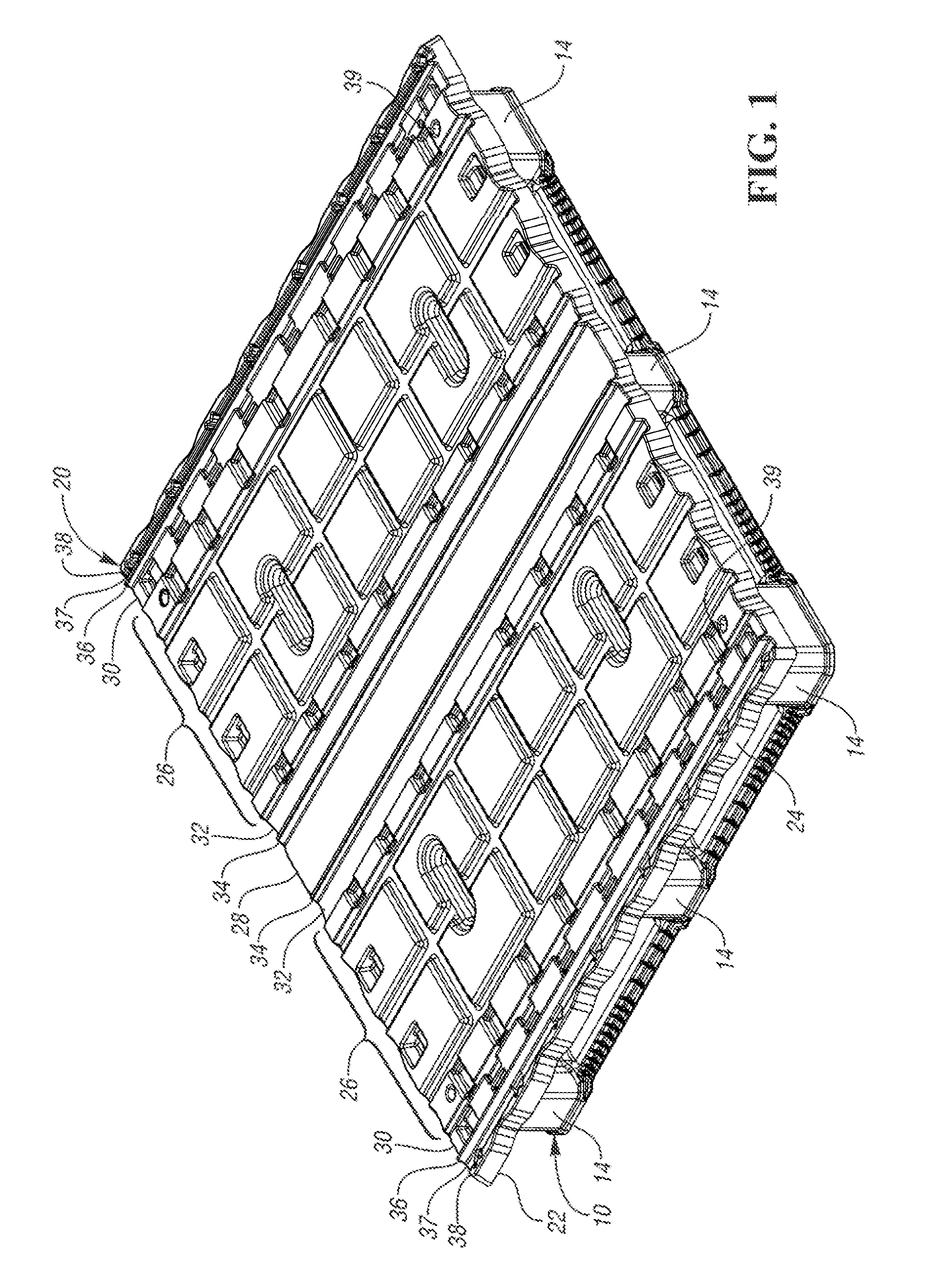
[0007] FIG. 1 is a perspective view of a pallet and pallet cap according to a first embodiment.
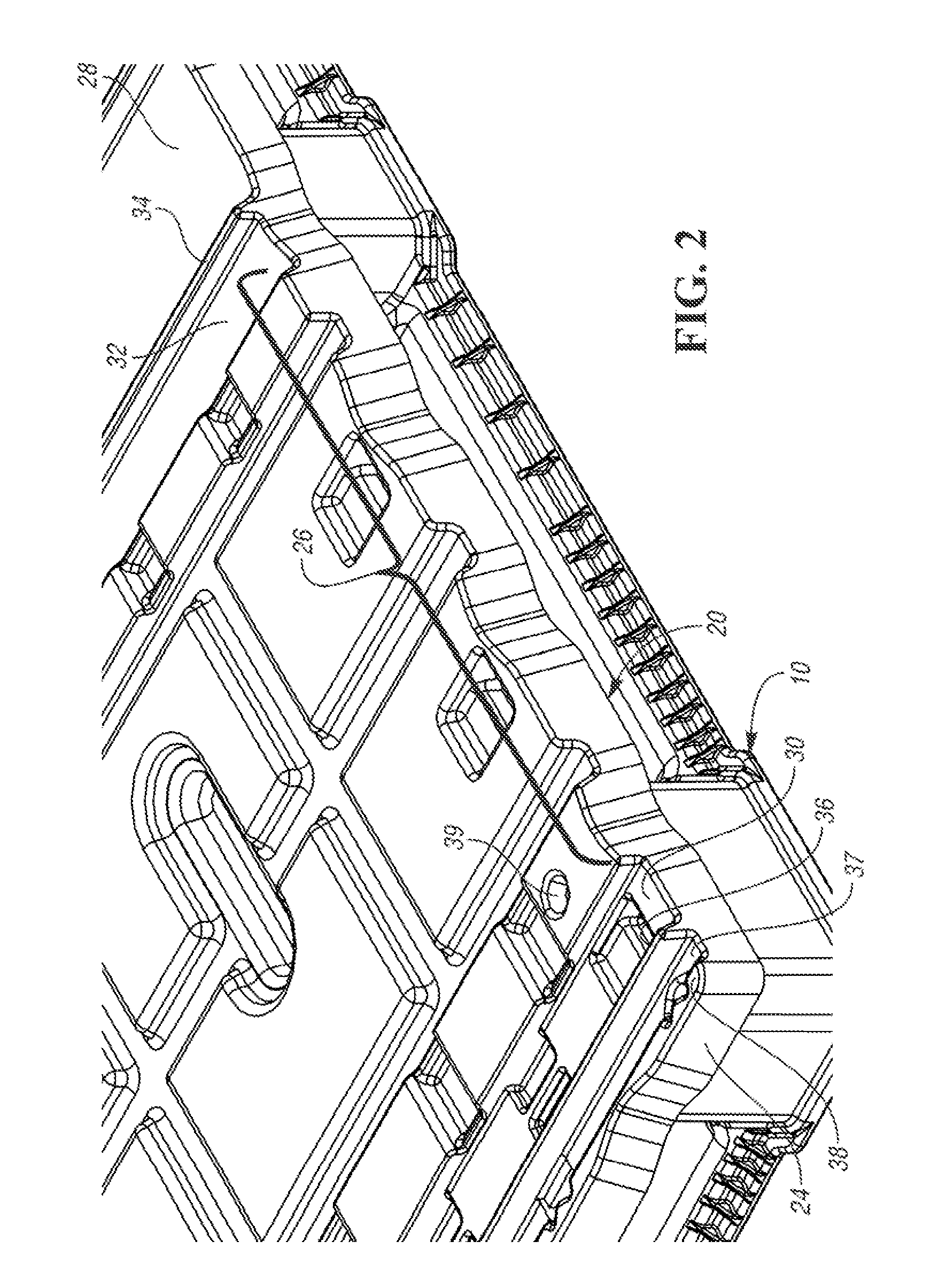
[0008] FIG. 2 is an enlarged view of a front corner of the pallet and pallet cap of FIG. 1.
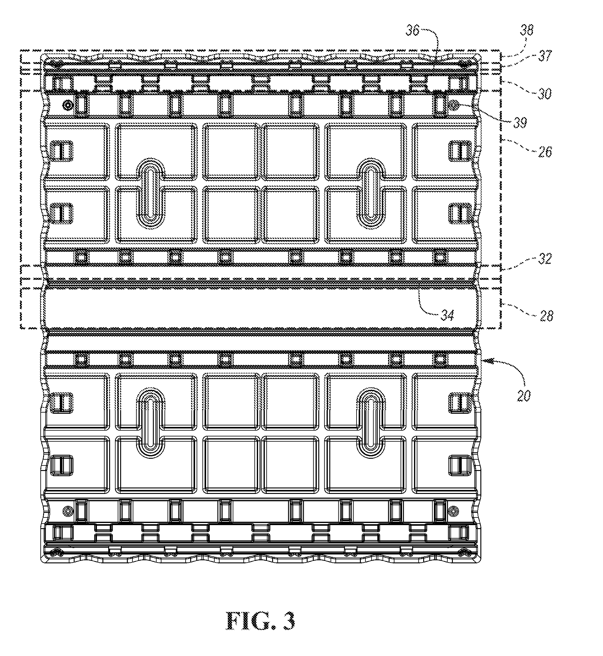
[0009] FIG. 3 is a top view of the pallet and pallet cap of FIG. 1.
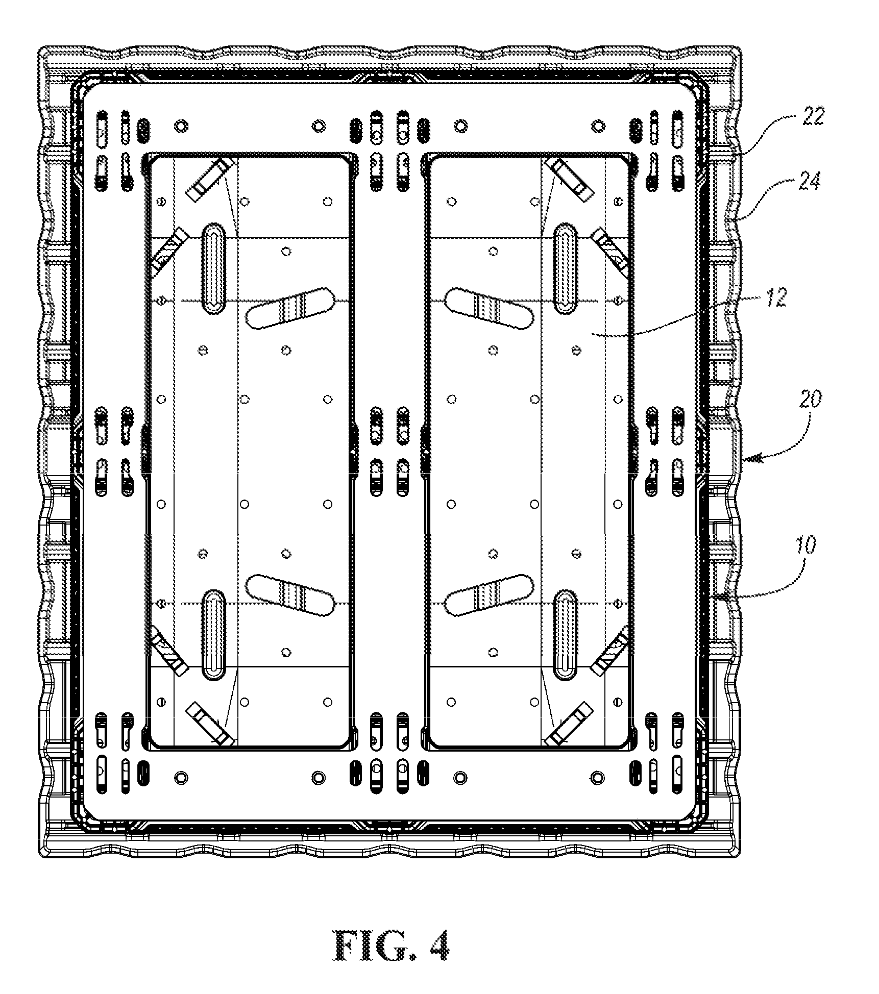
[0010] FIG. 4 is a bottom view of the pallet and pallet cap of FIG. 1.
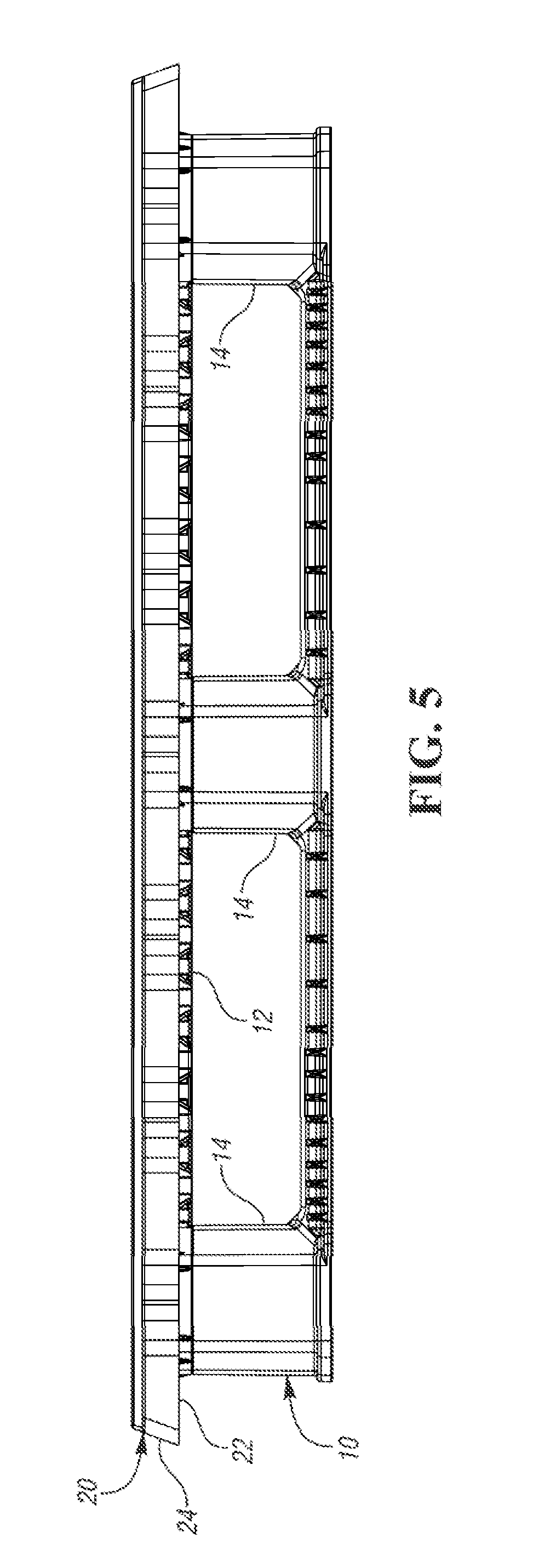
[0011] FIG. 5 is a side view of the pallet and pallet cap.
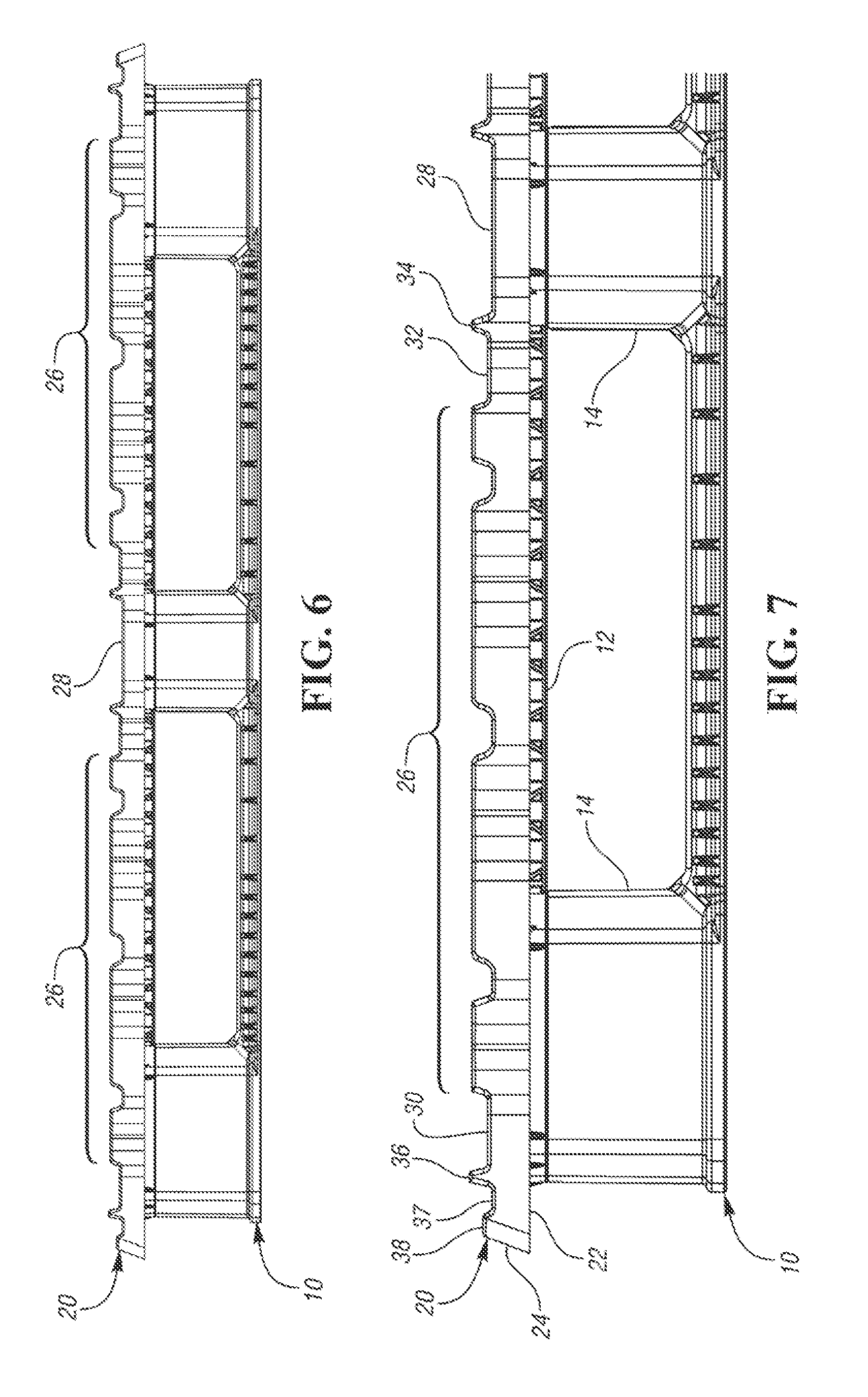
[0012] FIG. 6 is a front view of the pallet and pallet cap.
[0013] FIG. 7 is an enlarged view of a portion of the pallet and pallet cap of FIG. 6.
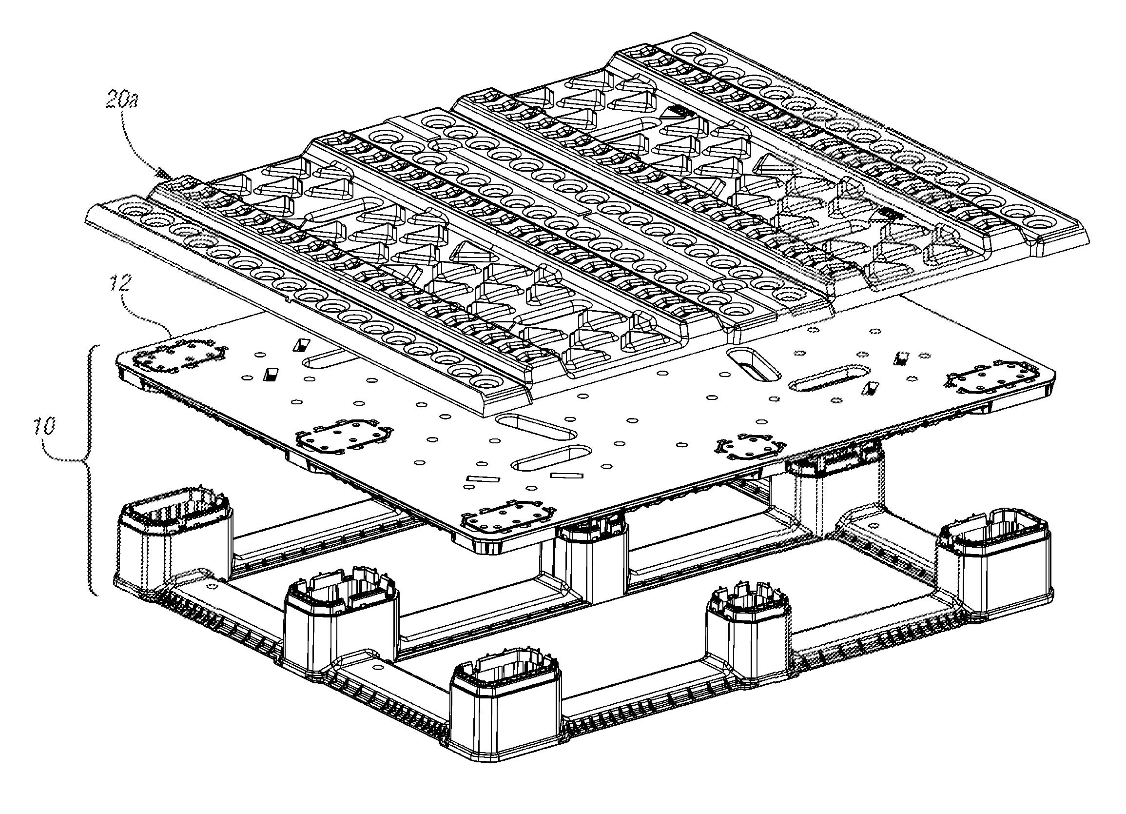
[0014] FIG. 8 is an exploded view of the pallet and pallet cap of FIG. 1.
[0015] FIG. 9 is a view similar to FIG. 8 with an alternate pallet cap.
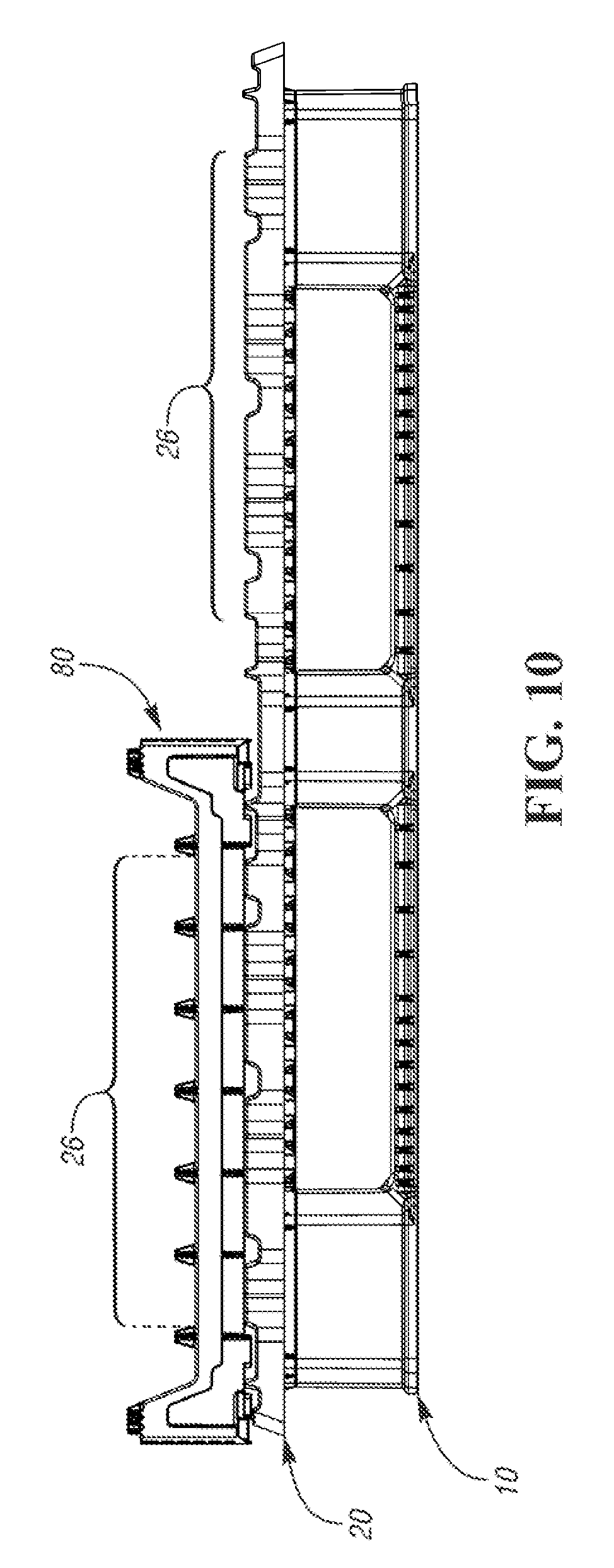
[0016] FIG. 10 is a front view of the pallet and pallet cap of FIG. 1, with a tray positioned on the pallet cap.
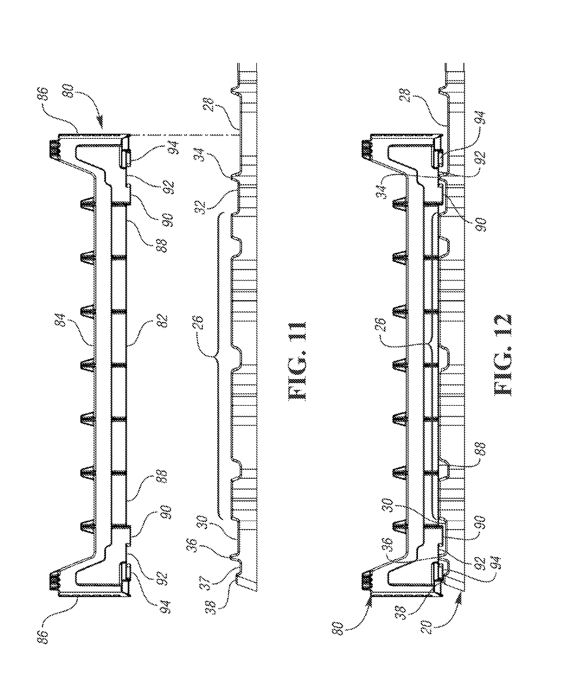
[0017] FIG. 11 is an enlarged view of a portion of the pallet cap with the tray spaced above to show alignment features.
[0018] FIG. 12 is a view similar to FIG. 11 with the tray engaged on the pallet cap.
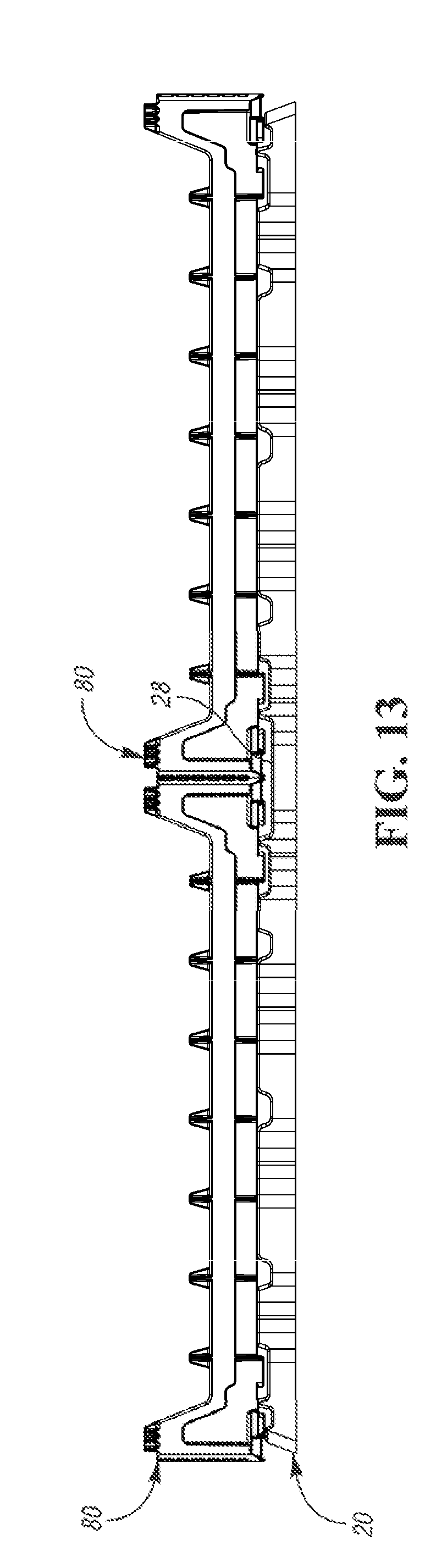
[0019] FIG. 13 is a front view showing two rows of trays engaged with the pallet cap.
DESCRIPTION OF A PREFERRED EMBODIMENT
[0020] A pallet 10 and pallet cap 20 are shown together in FIG. 1. The pallet 10 may be a known plastic pallet 10 having a deck 12 (FIG. 5) and a plurality of columns 14 supporting the deck 12. The deck 12 of the pallet 10 may be a standard size, such as 48.times.40 inches. Runners may connect lower ends of the columns 14 as shown. The pallet cap 20 is secured to the deck 12 of the pallet 10 to provide a surface for engaging containers to be supported by the pallet 10, such as bakery trays. The pallet cap 20 may include a peripheral portion 22 that projects outward from the perimeter of the pallet 10 and a lip 24 projecting downward from an outer edge of the peripheral portion 22. The outer edges of the pallet cap 20 and the corresponding lip 24 are not straight, but rather have several waves or scallops, which add reinforcement to support weight on the peripheral portion 22 that is cantilevered from the deck 12 of the pallet 10.
[0021] The example pallet cap 20 is thermoformed from a single sheet of plastic, but it could alternatively be injection molded or multi-sheet thermoformed. The pallet cap 20 includes a plurality of raised surfaces and channels as will be detailed below. These raised surfaces and channels are configured to engage containers stacked thereon. The engagement features on the pallet cap 20 can be considered a plurality of parallel raised surfaces and parallel channels for engaging two rows of trays. There would be two or more stacks of trays in each row. The engagement features in one of the two rows will be described, but the engagement features on the other half of the pallet cap 20 would be the same.
[0022] FIG. 2 is an enlarged view of the front corner of the pallet 10 and pallet cap 20 of FIG. 1. FIG. 3 is a top view of the pallet 10 and pallet cap 20 of FIG. 1. Referring to FIGS. 1-3, each half includes a central raised area 26, which may include a plurality of channels, which may only be for reinforcement. A central channel 28 runs along the division between the two halves of the pallet cap 20, but half of the central channel 28 is in each half of the pallet cap 20. A first inner channel 30 is immediately adjacent each central raised area 26, toward the nearest edge of the pallet cap 20. Also immediately adjacent each central raised area 26, opposite the first inner channel 30, is a second inner channel 32. Immediately adjacent each second inner channel 32 is an inner ridge 34, which is also immediately adjacent the central channel 28. Immediately adjacent each first inner channel 30, toward the nearest edge of the pallet cap 20, is an outer ridge 36. Immediately adjacent the outer ridge 36 is an outer channel 37 and then a peripheral ridge 38, which forms the outermost edge of the upper surface of the pallet cap 20.
[0023] A plurality of recesses 39 provide fastening points for securing the pallet cap 20 to the deck 12 of the pallet 10, such as with screws, bolts, rivets, hook-and-loop fasteners, etc. Adhesive could also be used, but removable fastening methods are preferred so that a damaged pallet cap 20 can easily be removed and replaced.
[0024] FIG. 4 is a bottom view of the pallet 10 and pallet cap 20 of FIG. 1. As shown, the pallet cap 20 may project outward of the deck 12 of the pallet 10 all around the perimeter of the deck 12.
[0025] FIG. 5 is a side view of the pallet 10 and pallet cap 20. Again, the pallet cap 20 may include the peripheral portion 22 that projects outward from the perimeter of the pallet 10 and the lip 24 projecting downward from an outer edge of the peripheral portion 22.
[0026] FIG. 6 is a front view of the pallet 10 and pallet cap 20. Again, each half includes the central raised area 26, which may include a plurality of channels, e.g. for reinforcement. The central channel 28 runs along the mid-line of the pallet cap 20, the mid-line defining the two halves of the pallet cap 20. There is a central raised area 26 in each half of the pallet cap 20, on each side of the central channel 28.
[0027] FIG. 7 is an enlarged view of one side of the pallet 10 and pallet cap 20 of FIG. 6 (just over half is shown). Immediately adjacent each central raised area 26, toward the nearest edge of the pallet cap 20, is the first inner channel 30. On the side of each central raised area 26 opposite the first inner channel 30 and immediately adjacent the central raised area 26 is the second inner channel 32. Between the second inner channel 32 and the central channel 28 is the inner ridge 34, which is immediately adjacent the central channel 28. Between the first inner channel 30 and the nearest edge of the pallet cap 20 is the outer ridge 36. Outward of the outer ridge 36 is the outer channel 37, and then the peripheral ridge 38, which forms the outermost edge of the upper surface of the pallet cap 20. The outer ridge 36, inner ridge 34 and at least some of the central raised area 26 are generally coplanar and are the highest surfaces of the pallet cap 20. The first inner channel 30 and second inner channel 32 are recessed relative to the outer ridge 36, inner ridge 34 and central raised area 26, but are not recessed as much as the outer channel 37, the central channel 28 and some channels formed in the central raised area 26 (for reinforcement). The relative heights and depths are shown to scale in the views of FIG. 6 and FIG. 7.
[0028] FIG. 8 is an exploded view of the pallet 10 and pallet cap 20. As shown in this example, the pallet 10 includes two injection-molded pieces (one includes the deck 12 and one includes the columns 14 and runners) which are subsequently secured to one another via snap-fit, vibration welding, hot plate welding, adhesive, etc.
[0029] As shown in FIG. 9, the pallet cap 20 could replace an alternate pallet cap 20a on the same pallet 10. The alternate pallet cap 20a may be removed and replaced with the pallet cap 20 to provide the interlocking features described herein for interlocking with containers stacked thereon.
[0030] FIG. 10 shows the pallet 10 and pallet cap 20 supporting a tray 80. It should be understood that it is intended that stacks of trays 80 would be stacked on the pallet cap 20 on the pallet 10. Again the pallet cap 20 supports two rows of trays 80, with multiple stacks of trays 80 each on half the pallet cap 20.
[0031] FIG. 11 shows the tray 80 spaced above the pallet cap 20 (only a portion of the pallet cap 20 is shown, to enlarge the view). The tray 80 is similar to existing plastic bakery trays and includes a base 82, dropped front and rear walls 84 and side walls 86. The base 82 includes a pair of inner guides 90 defining a large recess 88 therebetween. A first channel 92 is defined outward of each of the inner guides 90 and inward of outer guides 94.
[0032] As shown in FIG. 12, these guides 90, 94 and recess 88 and first channels 92 interlock with or engage the engagement features of the pallet cap 20. The outer guides 94 are supported on the peripheral ridge 38 and in the central channel 28. The first channels 92 receive the outer ridge 36 and inner ridge 34. The inner guides 90 are received in the first inner channel 30 and second inner channel 32. The large recess 88 in the base, between the inner guides 90, receives the central raised area 26. In this manner the engagement features retain the trays 80 on the pallet cap 20 and pallet 10.
[0033] FIG. 13 shows two of the trays 80 engaged and supported on the pallet cap 20 (which would be secured to the pallet 10, not shown). One tray 80 is shown in each row, but it should be understood that multiple trays 80 (and multiple stacks of trays 80) would be supported in each row.
[0034] In accordance with the provisions of the patent statutes and jurisprudence, exemplary configurations described above are considered to represent preferred embodiments of the invention. However, it should be noted that the invention can be practiced otherwise than as specifically illustrated and described without departing from its spirit or scope. For example, although the pallet cap 20 is shown as used with a pallet with runners (or a lower deck), the pallet cap could also be used with a nestable pallet, with corresponding openings through the pallet cap to receive the feet of a similar pallet nested thereon.
* * * * *
D00000
D00001
D00002
D00003
D00004
D00005
D00006
D00007
D00008
D00009
D00010
D00011
XML
uspto.report is an independent third-party trademark research tool that is not affiliated, endorsed, or sponsored by the United States Patent and Trademark Office (USPTO) or any other governmental organization. The information provided by uspto.report is based on publicly available data at the time of writing and is intended for informational purposes only.
While we strive to provide accurate and up-to-date information, we do not guarantee the accuracy, completeness, reliability, or suitability of the information displayed on this site. The use of this site is at your own risk. Any reliance you place on such information is therefore strictly at your own risk.
All official trademark data, including owner information, should be verified by visiting the official USPTO website at www.uspto.gov. This site is not intended to replace professional legal advice and should not be used as a substitute for consulting with a legal professional who is knowledgeable about trademark law.