Aircraft Undercarriage With Braked And Motor-driven Wheels
RAVEL; Jean-Yves
U.S. patent application number 16/171756 was filed with the patent office on 2019-05-02 for aircraft undercarriage with braked and motor-driven wheels. This patent application is currently assigned to SAFRAN LANDING SYSTEMS. The applicant listed for this patent is SAFRAN LANDING SYSTEMS. Invention is credited to Jean-Yves RAVEL.
| Application Number | 20190127053 16/171756 |
| Document ID | / |
| Family ID | 60627886 |
| Filed Date | 2019-05-02 |
| United States Patent Application | 20190127053 |
| Kind Code | A1 |
| RAVEL; Jean-Yves | May 2, 2019 |
AIRCRAFT UNDERCARRIAGE WITH BRAKED AND MOTOR-DRIVEN WHEELS
Abstract
The invention relates to an aircraft undercarriage provided at its bottom end with a rocker arm (2) carrying at least two axles (4, 5), including one in front of a hinge between the rocker arm and the undercarriage and the other behind said hinge. According to the invention, one of the axles is fitted with one or more braked wheels (6) and the other axle is fitted with one or more motor-driven wheels (8).
| Inventors: | RAVEL; Jean-Yves; (Velizy-Villacoublay, FR) | ||||||||||
| Applicant: |
|
||||||||||
|---|---|---|---|---|---|---|---|---|---|---|---|
| Assignee: | SAFRAN LANDING SYSTEMS Velizy Villacoublay FR |
||||||||||
| Family ID: | 60627886 | ||||||||||
| Appl. No.: | 16/171756 | ||||||||||
| Filed: | October 26, 2018 |
| Current U.S. Class: | 1/1 |
| Current CPC Class: | B64C 25/34 20130101; B64C 25/20 20130101; B64C 25/60 20130101; B64C 25/405 20130101; B64C 2025/345 20130101; B64C 25/36 20130101; Y02T 50/80 20130101; B64C 25/42 20130101; B64C 25/22 20130101 |
| International Class: | B64C 25/20 20060101 B64C025/20; B64C 25/42 20060101 B64C025/42; B64C 25/60 20060101 B64C025/60; B64C 25/34 20060101 B64C025/34; B64C 25/40 20060101 B64C025/40; B64C 25/22 20060101 B64C025/22 |
Foreign Application Data
| Date | Code | Application Number |
|---|---|---|
| Oct 27, 2017 | FR | 1760199 |
Claims
1. An aircraft undercarriage provided at its bottom end with a rocker arm (2) carrying at least two axles (4, 5), including one in front of a hinge between the rocker arm and the undercarriage and the other behind said hinge, the undercarriage being characterized in that one of the axles is fitted with one or more braked wheels (6) and the other axle is fitted with one or more motor-driven wheels (8).
2. An undercarriage according to claim 1, wherein the braked wheels (6) are carried by the front axle (4) and the motor-driven wheels (8) are carried by the rear axle (5).
3. An undercarriage according to claim 1, including a rocking shock absorber (10) acting on the rocker arm to exert at least one of the following actions: controlling the angle between the rocker arm (2) and the leg (1) during a stage of raising the undercarriage; damping oscillatory movements of the rocker arm (2) about the pivot (3); and distributing the vertical load taken up by the wheels by exerting a controlled thrust force on the rocker arm (2).
Description
[0001] The invention relates to an aircraft undercarriage with braked and motor-driven wheels
BACKGROUND OF THE INVENTION
[0002] Aircraft undercarriages are known that carry wheels, each of which is associated with a respective brake. Recent developments have led to proposing motor drive for such wheels in order to enable aircraft to move without help from its engines. It is technically difficult to fit a wheel with a motor when the wheel is already provided with a brake, in particular for reasons of available space and cooling. In particular, the rim of the wheel is already filled to a considerable extent by the disks of the brake, and there is very little room to arrange a motor and its coupling device in the space available in the immediate proximity of the wheel. Proposals have thus been made to specialize wheels, by fitting an aircraft both with wheels that are braked only and with wheels that are motor-driven only, each kind of wheel being much simpler to design and mount on an undercarriage. In particular, proposals are made in Document FR 3 019 796 to provide undercarriages with braked wheels only and to provide an auxiliary leg with one or more motor-driven wheels in order to move the aircraft, the auxiliary leg being deployed after the aircraft has landed on the ground. That arrangement raises the question of deploying at least one additional leg, which makes the undercarriages more difficult to manage.
OBJECT OF THE INVENTION
[0003] The invention seeks to propose a simplification to that arrangement, while retaining the principle of specializing wheels.
SUMMARY OF THE INVENTION
[0004] In order to achieve this object, there is provided an aircraft undercarriage provided at its bottom end with a rocker arm carrying at least two axles, including one in front of a hinge between the rocker arm and the undercarriage and the other behind said hinge, one of the axles is fitted with one or more braked wheels and the other axle is fitted with one or more motor-driven wheels.
[0005] The term "front" and "rear" should be understood relative to the usual forward travel direction of the aircraft. Thus, the wheels, all of which are specialized, are carried by a single undercarriage, so there is no point in making use of an additional leg, with the undercarriages then being managed in the usual way. All of the wheels support the weight of the aircraft and thus contribute actively to distributing said weight on the runway, both during landing and while taxiing. Specializing each of the axles also makes it possible to simplify routing cables and pipes by segregating on opposite sides of the leg the cables and pipes needed for controlling the brakes, and the cables needed for controlling the drive motors.
DESCRIPTION OF THE FIGURES
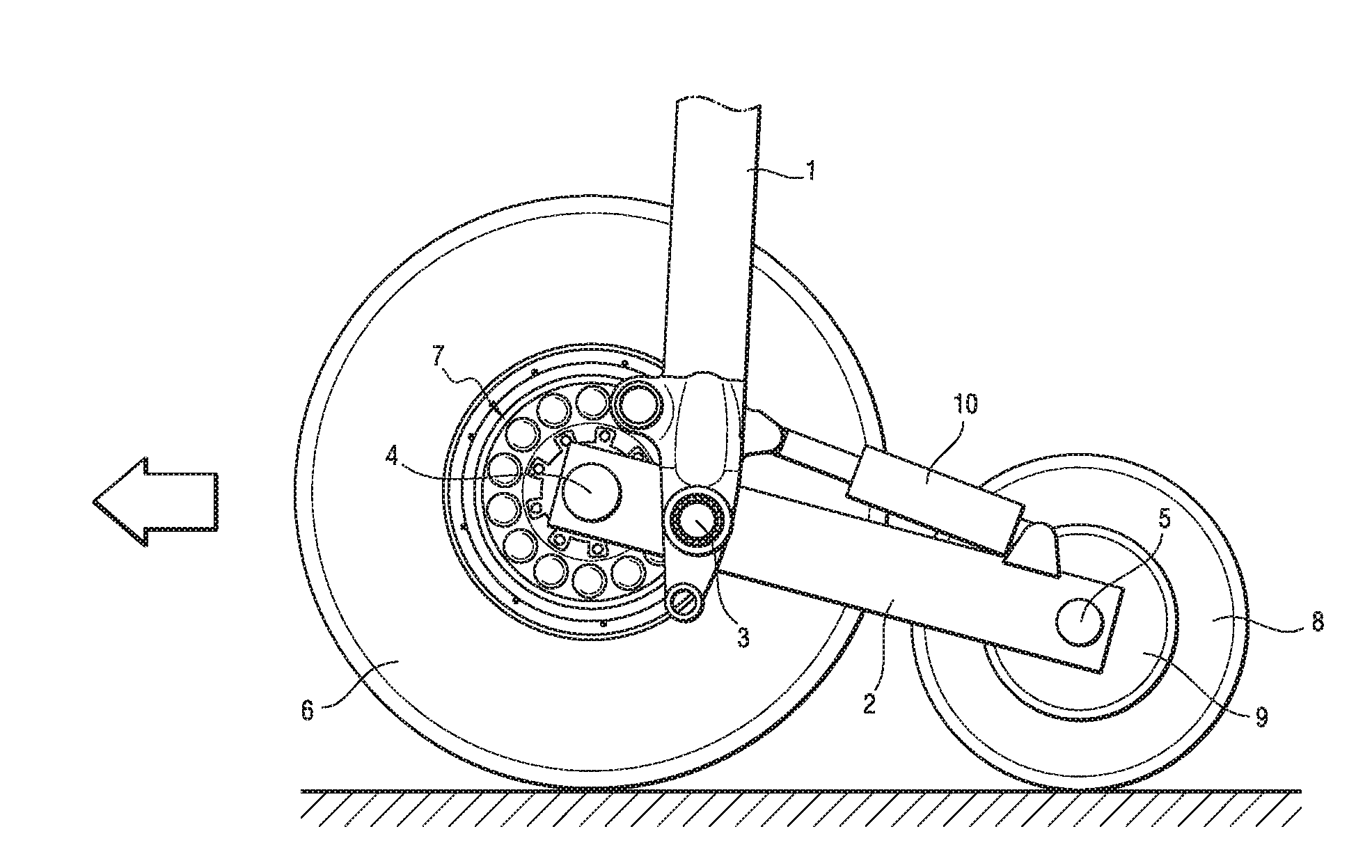
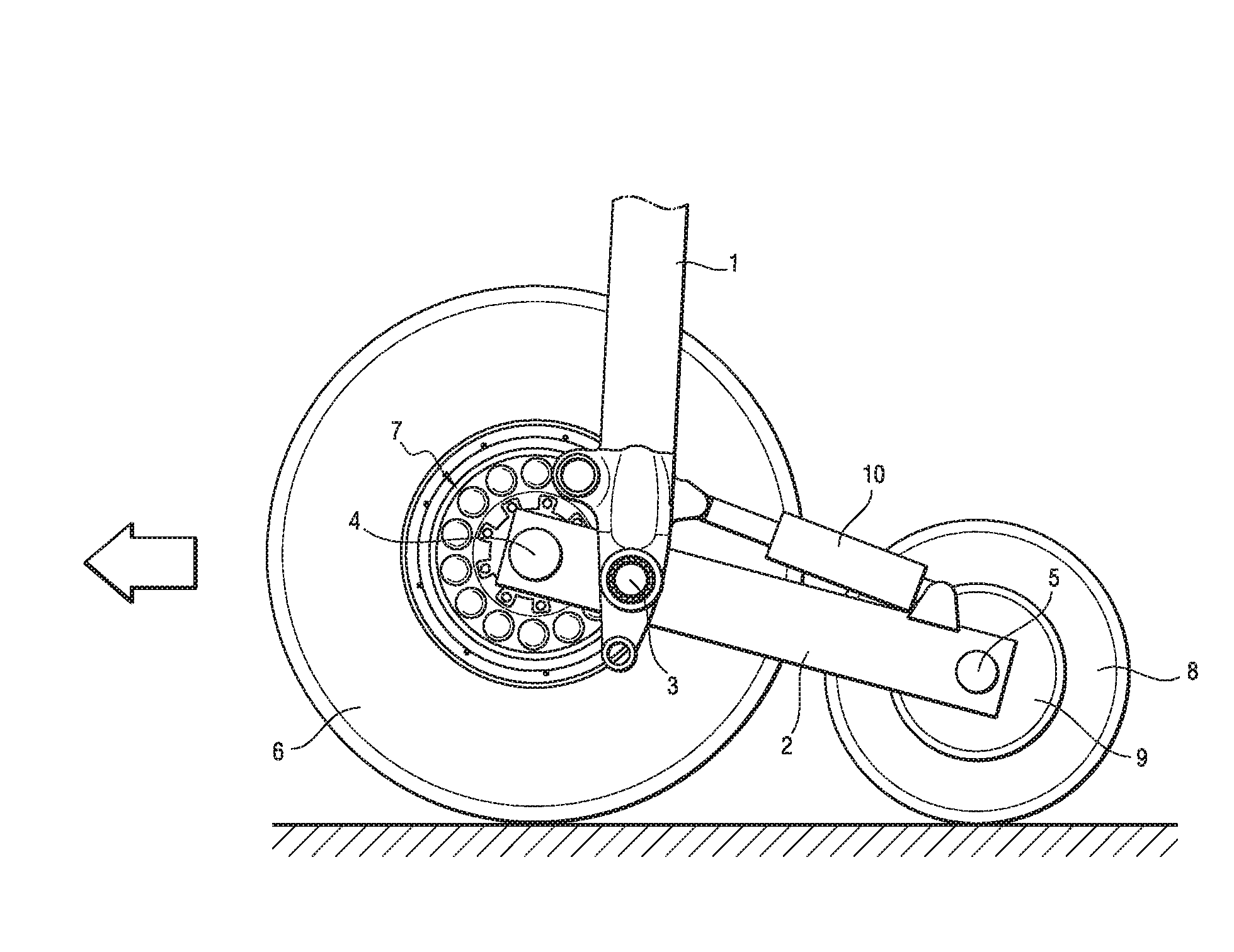
[0006] The invention can be better understood in the light of the following description of a particular embodiment of the invention given with reference to the sole accompanying FIGURE, which is a fragmentary side view of an aircraft undercarriage of the invention in the deployed position, with two wheels that would normally hide the rocker arm being omitted for greater clarity.
DETAILED DESCRIPTION OF THE INVENTION
[0007] The undercarriage of the invention shown herein has a leg 1 that is secured to the structure of the aircraft and that carries, at its bottom end, a rocker arm 2 that is hinged to the leg at a pivot 3. The rocker arm carries a front axle 4 lying in front of the pivot 3 and a rear axle 5 lying behind the pivot 3. The arrow to the left in the FIGURE indicates the usual direction of forward travel of the aircraft.
[0008] According to the invention, the front axle 4 carries two wheels 6 that are provided with brakes 7 (referred to herein as braked wheels, with only one braked wheel being visible in the FIGURE), while the rear axle 5 carries two wheels 8 that are provided with drive motors 9 (referred to herein as motor-driven wheels, with only one motor-driven wheel being visible in the FIGURE). Thus, while landing, the braked wheels 6 and the motor-driven wheels 8 touch the ground and together contribute to transmitting the weight of the aircraft to the ground. Only the braked wheels 6 contribute to slowing down the aircraft. Once the aircraft has landed on the ground, it is then possible to move the aircraft by means of the motor-driven wheels 8. The sequence for maneuvering the undercarriages is strictly identical to that of a conventional aircraft.
[0009] Since the braked wheels and the motor-driven wheels do not have the same functions, it is possible to give them different functional characteristics (diameter, size, tire inflation pressure, . . . ) in order to optimize their respective functions. Thus, in the example shown, the braked wheels 6 and their tires are greater in diameter than the motor-driven wheels 8. Likewise, the pivot 3 is not necessarily located in the middle of the rocker arm 2, but may be offset so as to cause more weight to be carried by the wheels of one or the other of the axles. Specifically, in this example, the pivot 3 is closer to the front axle 4 than to the rear axle 5, such that the braked wheels 6 are more heavily loaded than the motor-driven wheels 8.
[0010] In a particular aspect of the invention, a rocking shock absorber 10 is coupled between the leg 1 and the rocker arm 2 in order to exert at least one of the following actions: [0011] control the angle between the rocker arm 2 and the leg 1 while the undercarriage is being raised; [0012] damp oscillating movements of the rocker arm about the pivot 3; and [0013] distribute the vertical load taken up by the front and rear wheels by exerting a controlled thrust force on the rocker arm 2.
[0014] To this end, the rocking shock absorber 10 includes adjustment means that are controlled to vary its length, its stiffness, and/or its ability to absorb shocks. In particular, the shock absorber 10 is preferably controlled so as to apply a force on the rocker arm 2 that tends to press the motor-driven wheels 8 against the ground while their motors are being operated to cause the aircraft to advance, thereby having the effect of increasing the load on said wheels and thus increasing their effectiveness in driving the aircraft. In addition, such a force can assist the aircraft in taking off by artificially lengthening the leg by pivoting the rocker arm once the braked wheels leave the ground. The invention is not limited to the above description, but on the contrary covers any variant coming within the ambit defined by the claims. In particular, although each axle in this example carries two wheels, the invention may be applied to an undercarriage in which each axle carries only one wheel, or on the contrary carries more than two wheels, providing each axle carries wheels of only one type (braked wheels or motor-driven wheels).
[0015] In addition, although the distribution of load on the wheels of the front axle and the wheels of the rear axle can be modified by controlling the rocking shock absorber so that it exerts a force on the rocker arm, it is possible to use other means for distributing load, such as for example making provision for the pivot 3 of the rocker arm 2 to move longitudinally.
* * * * *
D00000
D00001
XML
uspto.report is an independent third-party trademark research tool that is not affiliated, endorsed, or sponsored by the United States Patent and Trademark Office (USPTO) or any other governmental organization. The information provided by uspto.report is based on publicly available data at the time of writing and is intended for informational purposes only.
While we strive to provide accurate and up-to-date information, we do not guarantee the accuracy, completeness, reliability, or suitability of the information displayed on this site. The use of this site is at your own risk. Any reliance you place on such information is therefore strictly at your own risk.
All official trademark data, including owner information, should be verified by visiting the official USPTO website at www.uspto.gov. This site is not intended to replace professional legal advice and should not be used as a substitute for consulting with a legal professional who is knowledgeable about trademark law.