Cheek And Tongue Retractor
ALZAIN; SAHAR ASAAD
U.S. patent application number 15/801222 was filed with the patent office on 2019-05-02 for cheek and tongue retractor. The applicant listed for this patent is KING SAUD UNIVERSITY. Invention is credited to SAHAR ASAAD ALZAIN.
| Application Number | 20190125491 15/801222 |
| Document ID | / |
| Family ID | 66245862 |
| Filed Date | 2019-05-02 |
| United States Patent Application | 20190125491 |
| Kind Code | A1 |
| ALZAIN; SAHAR ASAAD | May 2, 2019 |
CHEEK AND TONGUE RETRACTOR
Abstract
The retractor is a generally U-shaped device for protecting the cheek and tongue from instruments used during dental and prosthodontic procedures. The retractor has a planar base defined by two spaced arms, a pair of upright shields extending from the arms, and a posterior connector connecting the shields. The base is contoured to grip the tooth adjacent to the tooth to be treated, and thereby, secure the retractor within the patient's mouth.
| Inventors: | ALZAIN; SAHAR ASAAD; (RIYADH, SA) | ||||||||||
| Applicant: |
|
||||||||||
|---|---|---|---|---|---|---|---|---|---|---|---|
| Family ID: | 66245862 | ||||||||||
| Appl. No.: | 15/801222 | ||||||||||
| Filed: | November 1, 2017 |
| Current U.S. Class: | 1/1 |
| Current CPC Class: | A61C 5/80 20170201; A61B 13/00 20130101; A61B 1/24 20130101; A61C 5/90 20170201 |
| International Class: | A61C 5/90 20060101 A61C005/90; A61B 13/00 20060101 A61B013/00 |
Claims
1. A U-shaped cheek and tongue retractor adapted to clasp onto a tooth, consisting of: an elongated planar base having a longitudinal axis and including a pair of spaced apart arms, each of the arms having a curved first end, a straight second end thereby defining the U-shaped retractor, and a V-shaped protrusion extending laterally between the first end and the second end thereby forming a tooth engaging clasp portion adjacent the curved first end; a pair of upright, straight shields extending from the arms of the base and being coextensive therewith, each of the shields including a free first end and a second end, wherein the distance between the free ends of the shields is 4.0 cm and the distance between the arms of the base is 2.5 cm; and a posterior connector solely connecting the shields, wherein the connection is solely at the first end of the shields, further wherein the height of the posterior connector is 1.0 cm less than and the height of the shields is 2.5 cm thereby avoiding occlusal interference between opposing teeth.
2. The cheek and tongue retractor according to claim 1, wherein: each of the arms of the base include an aperture defined therethrough.
3-4. (canceled)
5. The cheek and tongue retractor according to claim 1, wherein the retractor is formed from a resilient material.
6. The cheek and tongue retractor according to claim 5, wherein the retractor is formed from a plastic material.
7. The cheek and tongue retractor according to claim 5, wherein the retractor is formed from a metal material.
8-11. (canceled)
Description
BACKGROUND
1. Field
[0001] The disclosure of the present patent application relates to dental appliances, and particularly to a cheek and tongue retractor for restorative and prosthodontic treatment.
2. Description of the Related Art
[0002] During restorative dentistry and prosthodontic procedures, clinicians are often required to utilize carbide and/or diamond burs for drilling, finishing, and/or grinding at high speeds. To protect the tongue and cheek of the patient during these procedures, clinicians typically use cheek and tongue retractors. Many conventional retractors, however, include hinged joints, mirrors, and/or handles, which can block or minimize a work area in the mouth. Further, the clinician must grasp a retractor handle to maintain the retractor in a desired position during the procedure. As such, conventional retractors can also be difficult to use.
[0003] Thus, a cheek and tongue retractor for restorative and prosthodontic treatment solving the aforementioned problems is desired.
SUMMARY
[0004] The retractor is a generally U-shaped device for protecting the cheek and tongue from instruments used during dental and prosthodontic procedures. The retractor has a planar base defined by two spaced arms, a pair of upright shields extending from the arms, and a posterior connector connecting the shields. The base is contoured to grip the tooth adjacent to the tooth to be treated, and thereby, secure the retractor within the patient's mouth.
[0005] These and other features of the present disclosure will become readily apparent upon further review of the following specification and drawings.
BRIEF DESCRIPTION OF THE DRAWINGS
[0006] FIG. 1 is an environmental, perspective view of a cheek and tongue retractor for restorative and prosthodontic treatment.
[0007] FIG. 2 is a plan view of the cheek and tongue retractor of FIG. 1.
[0008] FIG. 3 is a front view of the cheek and tongue retractor of FIG. 1.
[0009] FIG. 4 is a rear view of the cheek and tongue retractor of FIG. 1.
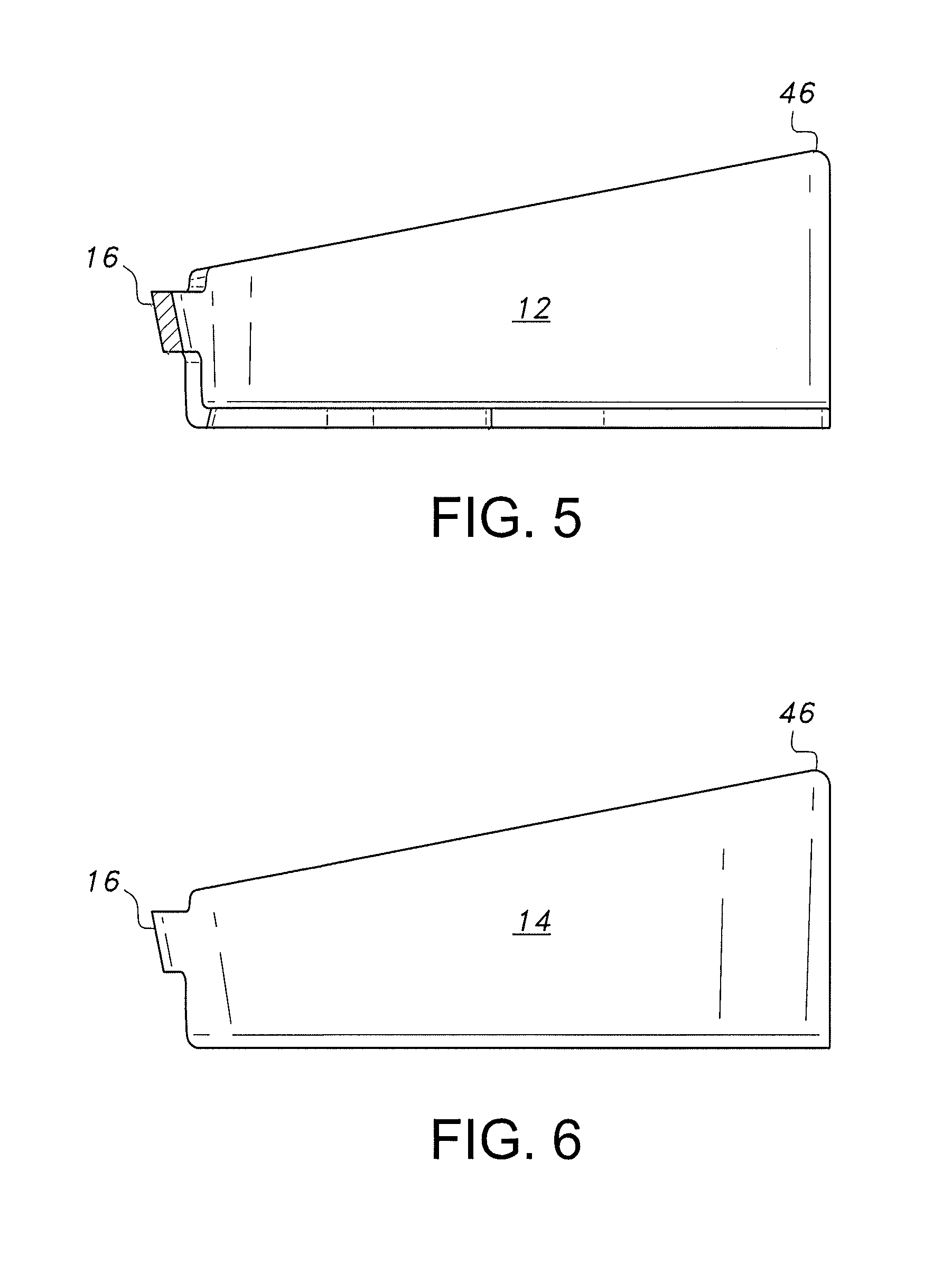
[0010] FIG. 5 is a section view drawn along lines 5-5 of FIG. 3.
[0011] FIG. 6 is a left side view of the cheek and tongue retractor of FIG. 1.
[0012] Similar reference characters denote corresponding features consistently throughout the attached drawings.
DETAILED DESCRIPTION OF THE PREFERRED EMBODIMENTS
[0013] The cheek and tongue retractor 10 can be used to protect the cheek and tongue from instruments used during dental and prosthodontic procedures. As is shown in FIGS. 1-6, the retractor 10 is a generally U-shaped device having a planar base 20, a buccal shield 12, a lingual shield 14, and a posterior connector 16 connecting the buccal shield 12 and the lingual shield 14. The base 20 is defined by a pair of spaced arms 40a, 40b. The buccal shield 12 and the lingual shield 14 extend generally upright from the arms 40a and 40b.
[0014] The base 20 is contoured to grip the tooth adjacent to the tooth to be treated, and thereby, secure the retractor 10 within the patient's mouth. Once secured to the adjacent tooth, the buccal shield 12 and the lingual shield 14 of the retractor 10 protect the check and tongue of the patient from instruments used during a procedure. It should be understood that the retractor 10 is self-retentive. In other words, an additional force is not required to hold the retractor 10 in place while a clinician is treating tooth O. Further, while the drawings show the buccal shield 12 adjacent to the cheek C and the lingual shield 14 adjacent to the tongue T, it should be understood that positioning the retractor 10 on an opposite side of the mouth can result in the buccal shield 12 being adjacent to the tongue T and the lingual shield 14 being adjacent to the cheek C.
[0015] As shown in FIGS. 1 and 2, the arms 40a, 40b of the base include curved first ends 42a, 42b, respectively, and opposing, straight second ends 44a, 44b, respectively. Arm 40a includes a generally V-shaped protrusion 45a extending between the first and second ends 42a, 44a toward arm 40b. Arm 40b includes a generally V-shaped protrusion 45b extending between the first and second ends 42b, 44b toward arm 40a. A base clasp portion 24 is defined by an area between the first curved ends and the protrusions of both of the arms 40a, 40b. A base frame portion 26 is defined by an area between the protrusions and the second ends of both of the arms 40a, 40b. The clasp portion 24 is configured for gripping the buccal and lingual undercuts of adjacent tooth A (the tooth adjacent to the tooth to be treated). The frame portion 26 is configured to extend along opposing sides of tooth O (the tooth to be treated). The base 20 can include apertures 21a, 21b, for receiving pins of forceps (not shown) or other tool which can be used to place the retractor in the mouth prior to a procedure.
[0016] In an exemplary embodiment, as shown in FIGS. 2-6, the distance W.sub.C between opposing second ends of the base is about 2.5 centimeters (FIG. 2). The distance W.sub.U between opposing ends of the two shields 12 and 14 is about 4.0 centimeters (FIG. 4). The height H.sub.S of each shield 12, 14 is about 2.5 centimeters, while the height H.sub.C of the connector is about 1.0 centimeter (FIG. 3). The height of the connector is preferably less than the height of the shields to avoid occlusal interferences between opposing teeth (FIGS. 5 and 6). It should be understood that the dimensions of the retractor 10 can vary depending on the size of the patient's teeth.
[0017] A clamp forceps can be used to place the retractor in the mouth of a patient. The pins of the clamp forceps can be inserted into apertures 20a, 20b. The clasp portion of the base 20 can then be positioned along buccal and lingual undercuts of the adjacent tooth A. Once the base 20 is secured to the adjacent tooth A, the forceps can be detached from the retractor.
[0018] The retractor 10 is preferably made from a resilient plastic or metal material. Preferably, the material can be sterilized in an autoclave without being distorted. The retractor parts can be rounded with smooth surfaces to avoid any possible tissue trauma.
[0019] It is to be understood that the cheek and tongue retractor for restorative and prosthodontic treatment is not limited to the specific embodiments described above, but encompasses any and all embodiments within the scope of the generic language of the following claims enabled by the embodiments described herein, or otherwise shown in the drawings or described above in terms sufficient to enable one of ordinary skill in the art to make and use the claimed subject matter.
* * * * *
D00000
D00001
D00002
D00003
D00004
XML
uspto.report is an independent third-party trademark research tool that is not affiliated, endorsed, or sponsored by the United States Patent and Trademark Office (USPTO) or any other governmental organization. The information provided by uspto.report is based on publicly available data at the time of writing and is intended for informational purposes only.
While we strive to provide accurate and up-to-date information, we do not guarantee the accuracy, completeness, reliability, or suitability of the information displayed on this site. The use of this site is at your own risk. Any reliance you place on such information is therefore strictly at your own risk.
All official trademark data, including owner information, should be verified by visiting the official USPTO website at www.uspto.gov. This site is not intended to replace professional legal advice and should not be used as a substitute for consulting with a legal professional who is knowledgeable about trademark law.