Devices And Systems For Providing Sensors In Parallel With Medical Tools
KRIMSKY; WILLIAM S. ; et al.
U.S. patent application number 16/150340 was filed with the patent office on 2019-05-02 for devices and systems for providing sensors in parallel with medical tools. The applicant listed for this patent is COVIDIEN LP. Invention is credited to WILLIAM S. KRIMSKY, JOSHUA B. STOPEK.
| Application Number | 20190125453 16/150340 |
| Document ID | / |
| Family ID | 64048826 |
| Filed Date | 2019-05-02 |


| United States Patent Application | 20190125453 |
| Kind Code | A1 |
| KRIMSKY; WILLIAM S. ; et al. | May 2, 2019 |
DEVICES AND SYSTEMS FOR PROVIDING SENSORS IN PARALLEL WITH MEDICAL TOOLS
Abstract
Disclosed are systems, devices, and methods for using sensor sleeves with surgical tools. In an aspect of the present disclosure, a sensor sleeve includes a tubular body defining a central longitudinal axis and having a lumen defined therethrough, the tubular body being configured to receive a tool, a plurality sensors attached to the tubular body, a cabling extending distally from the tubular body, and an interface connector coupled to the cabling and configured to interface with a navigation system.
| Inventors: | KRIMSKY; WILLIAM S.; (FOREST HILL, MD) ; STOPEK; JOSHUA B.; (MINNEAPOLIS, MN) | ||||||||||
| Applicant: |
|
||||||||||
|---|---|---|---|---|---|---|---|---|---|---|---|
| Family ID: | 64048826 | ||||||||||
| Appl. No.: | 16/150340 | ||||||||||
| Filed: | October 3, 2018 |
Related U.S. Patent Documents
| Application Number | Filing Date | Patent Number | ||
|---|---|---|---|---|
| 62579295 | Oct 31, 2017 | |||
| Current U.S. Class: | 1/1 |
| Current CPC Class: | A61B 2017/00477 20130101; A61B 1/00114 20130101; A61B 2034/2055 20160201; A61B 2034/2063 20160201; A61B 1/2676 20130101; A61B 1/00135 20130101; A61B 2034/2051 20160201; A61B 34/20 20160201; A61B 17/00234 20130101 |
| International Class: | A61B 34/20 20060101 A61B034/20; A61B 1/267 20060101 A61B001/267 |
Claims
1. A sensor sleeve for use with a tool, the sensor sleeve comprising: a tubular body defining a central longitudinal axis and having a lumen defined therethrough, the tubular body being configured to receive a tool; a plurality of sensors attached to the tubular body; a cabling extending distally from the tubular body; and an interface connector coupled to the cabling and configured to interface with a navigation system.
2. The sensor sleeve according to claim 1, wherein the cabling includes a plurality of attachments configured to secure the cabling to the tool.
3. The sensor sleeve according to claim 2, wherein the plurality of attachments are o-rings.
4. The sensor sleeve according to claim 2, wherein the plurality of attachments are adhesive pads.
5. The sensor sleeve according to claim 1, wherein the lumen has an inner surface fabricated at least partially from a lubricious material.
6. The sensor sleeve according to claim 1, wherein the tubular body is fabricated at least partially from a flexible biocompatible material.
7. The sensor sleeve according to claim 1, wherein the tubular body is cylindrical.
8. The sensor sleeve according to claim 1, wherein the plurality of sensors are selected from the group consisting of electromagnetic (EM) sensors, ultrasound sensors, optical sensors, and piezoelectric polyvinylidenefluoride (PVDF) film.
9. The sensor sleeve according to claim 1, wherein the tubular body further includes a first shell and a second shell hingedly connected together along a first axis that extends in a direction parallel to the central longitudinal axis.
10. The sensor sleeve according to claim 9, further including: a plurality of snaps attached to the first shell; and a plurality of recesses attached to the second shell.
11. The sensor sleeve according to claim 10, wherein the first shell and second shell are capable of hingedly opening along the first axis.
12. The sensor sleeve according to claim 10, wherein the tubular body is configured to transition from a first position to a second position.
13. The sensor sleeve according to claim 12, wherein the first position is open and the second position is closed.
14. The sensor sleeve according to claim 13, wherein, while in the first position, the first shell and the second shell are semi-cylindrical.
15. The sensor sleeve according to claim 13, wherein, while in the second position, the first shell and the second shell are connected along a second axis that extends in a direction parallel to the central longitudinal axis and the first axis.
16. The sensor sleeve according to claim 13, wherein, while in the second position, the plurality of snaps and the plurality of recesses are mateably engaged.
17. The sensor sleeve according to claim 9, wherein the tubular body is fabricated at least partially from a semi-rigid biocompatible material.
18. The sensor sleeve according to claim 1, wherein the tubular body includes an opening slit along an axis that extends in a direction parallel to the central longitudinal axis.
19. The sensor sleeve according to claim 18, wherein the tubular body is configured to transition from an open position to a closed position along the opening slit and is self-biased in the closed position.
Description
CROSS REFERENCE TO RELATED APPLICATION
[0001] The present application claims the benefit of dud priority to U.S. Provisional Application Ser. No. 62/579,295 filed on Oct. 31, 2017 the entire contents of which are incorporated herein by reference.
BACKGROUND
Technical Field
[0002] The present disclosure relates to medical instruments and, more specifically, to navigation sensors applied to surgical tools.
Description of Related Art
[0003] Tools used during medical procedures include diagnostic and therapeutic scopes. Diagnostic and therapeutic scopes are devices that may be used to navigate to and inspect various areas of a patient's body. One commonly-used scope is a bronchoscope. Typically, the bronchoscope is inserted into a patient's airways through the patient's nose or mouth and can extend into the patient's lungs. A typical bronchoscope includes an elongated flexible tube having an illumination assembly for illuminating the region distal to the bronchoscope's tip, and an imaging assembly for providing a video image from the bronchoscope's tip. Various instruments, e.g., diagnostic and therapeutic instruments and/or working channels may be inserted through the bronchoscope into the patient's airways.
[0004] While navigating within a patient, it may be necessary to determine the physical location of the bronchoscope within the patient. One method for determining the physical location of the bronchoscope is through the use of sensors placed on a tool or catheter utilized with the bronchoscope. An example system that utilizes such sensors is the ILOGIC ELECTROMAGNETIC NAVIGATION BRONCHOSCOPY (ENB) system currently sold by Medtronic PLC. The details of such a system are described in commonly-assigned U.S. Pat. No. 7,233,820, filed on Mar. 29, 2004, by Gilboa and entitled "ENDOSCOPE STRUCTURES AND TECHNIQUES FOR NAVIGATING TO A TARGET IN BRANCHED STRUCTURE," the entire contents of which are incorporated herein by reference. While the system as described in U.S. Pat. No. 7,233,820 is quite capable, there is always a need for development of improvements and additions to such systems.
SUMMARY
[0005] Provided in accordance with embodiments of the present disclosure are sensor sleeves for use with tools. In an aspect of the present disclosure, a sensor sleeve includes a tubular body defining a central longitudinal axis and having a lumen defined therethrough, the tubular body being configured to receive a tool, a plurality sensors attached to the tubular body, a cabling extending distally from the tubular body, and an interface connector coupled to the cabling and configured to interface with a navigation system.
[0006] In another aspect of the present disclosure, the cabling includes a plurality of attachments configured to secure the cabling to the tool.
[0007] In a further aspect of the present disclosure, the plurality of attachments are o-rings.
[0008] In another aspect of the present disclosure, the plurality of attachments are adhesive pads.
[0009] In yet another aspect of the present disclosure, the lumen has an inner surface fabricated at least partially from a lubricious material.
[0010] In still another aspect of the present disclosure, the tubular body is fabricated at least partially from a flexible biocompatible material.
[0011] In yet another aspect of the present disclosure, the tubular body is cylindrical.
[0012] In still another aspect of the present disclosure, the plurality of sensors are selected from the group consisting of electromagnetic (EM) sensors, ultrasound sensors, optical sensors, and piezoelectric polyvinylidenefluoride (PVDF) film.
[0013] In yet another aspect of the present disclosure, the tubular body further includes a first shell and a second shell hingedly connected together along a first axis that extends in a direction parallel to the central longitudinal axis.
[0014] In a further aspect of the present disclosure, the sensor sleeve further includes a plurality of snaps attached to the first shell, and a plurality of recesses attached to the second shell.
[0015] In yet a further aspect of the present disclosure, the first shell and second shell are capable of hingedly opening along the first axis.
[0016] In another aspect of the present disclosure, the tubular body is configured to transition from a first position to a second position.
[0017] In a further aspect of the present disclosure, the first position is open and the second position is closed.
[0018] In yet a further aspect of the present disclosure, while in the first position, the first shell and the second shell are semi-cylindrical.
[0019] In another aspect of the present disclosure, while in the second position, the first shell and the second shell are connected along a second axis that extends in a direction parallel to the central longitudinal axis and the first axis.
[0020] In yet another aspect of the present disclosure, while in the second position, the plurality of snaps and the plurality of recesses are mateably engaged.
[0021] In still another aspect of the present disclosure, the tubular body is fabricated at least partially from a semi-rigid biocompatible material.
[0022] In yet another aspect of the present disclosure, the tubular body includes an opening slit along an axis that extends in a direction parallel to the central longitudinal axis.
[0023] In a further aspect of the present disclosure, the tubular body is configured to transition from an open position to a closed position along the opening slit and is self-biased in the closed position.
BRIEF DESCRIPTION OF THE DRAWINGS
[0024] Objects and features of the presently disclosed devices and systems will become apparent to those of ordinary skill in the art when descriptions of various embodiments thereof are read with reference to the accompanying drawings, wherein:
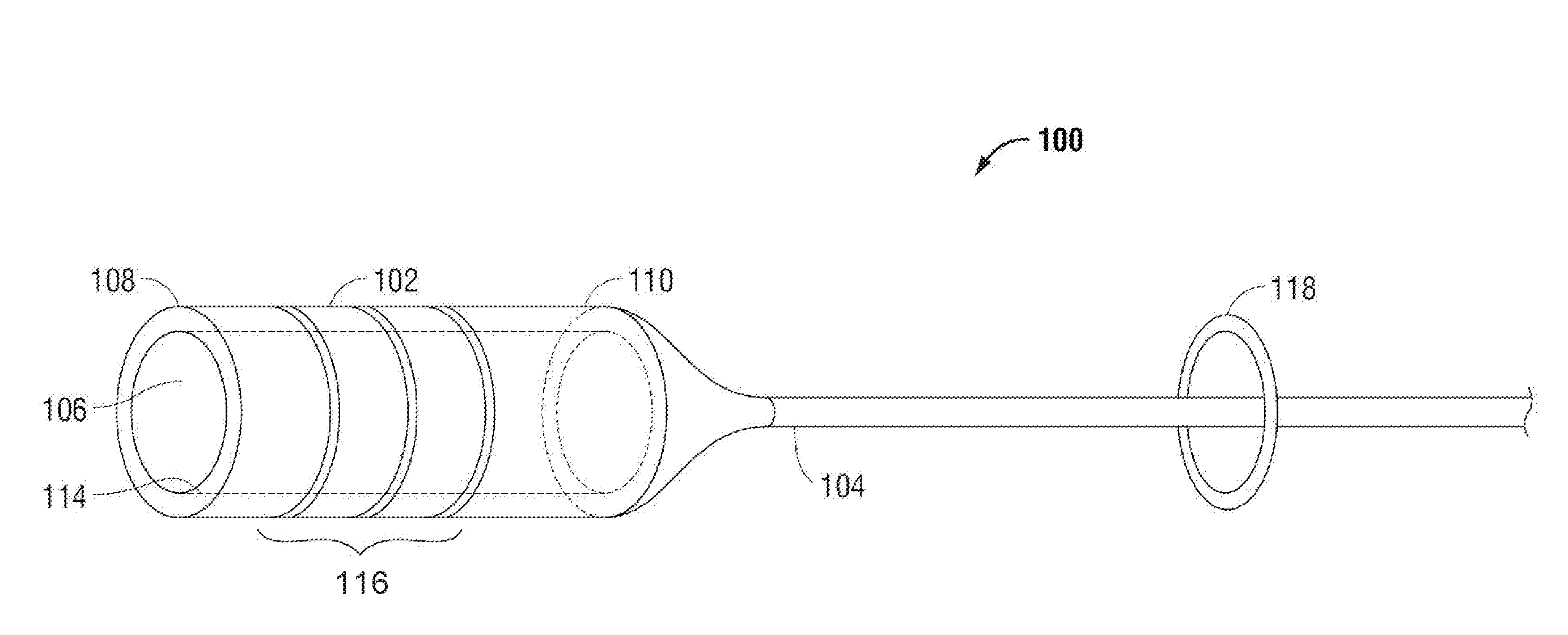
[0025] FIG. 1 is an illustration of a sensor sleeve, in accordance with one embodiment of the present disclosure;
[0026] FIG. 2A is an illustration of a sensor sleeve in a closed position, in accordance with a second embodiment of the present disclosure;
[0027] FIG. 2B is an illustration of the sensor sleeve of FIG. 2A in an open position, in accordance with the second embodiment of the present disclosure;
[0028] FIG. 3 is an illustration of a sensor sleeve including optical sensors, in accordance with an embodiment of the present disclosure;
[0029] FIG. 4A is an illustration of a scope for use with the sensor sleeves of the present disclosure;
[0030] FIG. 4B is an illustration of an endobronchial ultrasound (EBUS) bronchoscopy tool for use with the sensor sleeves of the present disclosure;
[0031] FIGS. 5A-5C are sequential operational illustrations of the sensor sleeve of FIG. 1 in use with the scope of FIG. 4A at various stages, in accordance with an embodiment of the present disclosure;
[0032] FIG. 6 is an illustration of the sensor sleeve of FIGS. 2A and 2B in use with the EBUS bronchoscopy tool of FIG. 4B, in accordance with an embodiment of the present disclosure; and
[0033] FIG. 7 illustrates an endobronchial navigation system which may be utilized with the present disclosure.
DETAILED DESCRIPTION
[0034] The present disclosure is directed to devices and systems for providing sensors in parallel with surgical tools. More particularly, the present disclosure is directed to devices for retrofitting various surgical tools, such as bronchoscopes, gastroscopes, endoscopes, and ultrasound scopes (referred to hereinafter as "tools"), with navigational, visualization, and/or other sensors. In addition to the aforementioned tools, those skilled in the art will recognize that the sensors and sensor sleeves described below may also be fitted to other surgical tools, such as laparoscopic tools, thorascoscopic tools, percutaneous tools, etc. Thus, while described below as attached to scopes and other devices with lumens, those skilled in the art will recognize that the sensors and sensor sleeves may also be used with tools without lumens. The sensors may include electromagnetic (EM) sensors, optical, ultrasound, as well as other sensors providing confirmation of location and, where appropriate, further visualization and imaging capabilities for the retrofitted tools. Types of optical sensors may include confocal, near-infrared, Raman spectroscopic, optical coherence tomography, narrow band, etc. Additional examples of types of sensors usable with the present disclosure include metabolic and/or thermal sensors configured to detect positron emission tomography (PET) avid lesions, radiation sensors configured to detect to radionuclides injected into the body to detect where they cluster, as well as pH related sensors and/or protein sensors, among others.
[0035] FIG. 1 depicts a first embodiment of the present disclosure illustrating a flexible sensor sleeve 100 for enabling the tracking of the location of a tool (FIG. 4A). Sensor sleeve 100 generally includes a tubular body 102 and a cabling 104. Tubular body 102 is a hollowed tubular member having a lumen 106 extending therethrough defining a central longitudinal axis. Tubular body 102 includes a distal portion 108, proximal portion 110, outer surface 112, and inner surface 114. As illustrated in FIG. 1, included on outer surface 112 of tubular body 102 are one or more sensors 116. In other embodiments, one or more sensors 116 are located between outer surface 112 and inner surface 114 within the material forming the tubular body 102.
[0036] Tubular body 102, as illustrated in FIG. 1, is cylindrical. It is contemplated that for sensor sleeve 100, the diameter of tubular body 102 ranges from about 2 mm to about 6 mm and is capable of being slideably fitted over similarly sized tools. In some embodiments, sensor sleeve 100 includes a cap (not shown) located at distal portion 108 which prevents further longitudinal movement of tools once fully inserted into sensor sleeve 100. Alternatively, tubular body 102 may include an area of reduced diameter proximate distal portion 108 which a tool, once fully inserted, is incapable of moving beyond. In other embodiments, as shown in FIGS. 1, 5C and 6, sensor sleeves 100 and 200 do not have a cap but remain stationary due to friction created by the interface of the tubular body 102 and the tool once inserted.
[0037] It is contemplated that sensor sleeve 100 is fabricated from flexible biocompatible materials such as silicone, urethane, thermo plastic elastomer, polyolefins, olefin copolymers, and vinyl polymers. Inner surface 114 may be formed of materials that are sufficiently lubricious that they allow a tool, such as bronchoscope 400 of FIG. 4A, to be slideably inserted. As will be appreciated by those skilled in the art, a compromise between lubricity and friction fit of tubular body 102 will result in appropriate materials being employed.
[0038] The one or more sensors 116 are, for example, EM sensors, such as those described in U.S. Pat. No. 7,233,820, optical imaging sensors, ultrasound sensors such as piezoelectric polyvinylidenefluoride (PVDF) film, and/or a combination thereof. In some embodiments, one or more sensors 116 are fabricated onto tubular body 102 of sensor sleeve 100. In further embodiments, one or more sensors 116 may be optical shape sensing fibers allowing sensing of shape and/or orientation data along an entire length of tubular body 102. Although illustrated as a plurality of rings on tubular body 102 of sensor sleeve 100, it is contemplated that one or more sensors 116 may form other configurations and shapes which provide location information. In the example of utilizing ultrasound sensors, in another embodiment, one or more sensors 116 are located at distal portion 108 of sensor sleeve 100, such that when using sensor sleeve 100, ultrasound imaging may be undertaken. One or more sensors 116 may be configured to connect to a workstation, such as workstation 780 (FIG. 7), via wired and/or wireless connection. For example, one or more sensors 116 may be connected to workstation 780 via one or more wires included in cabling 104 and/or via a wireless connection, such as a BLUETOOTH connection. In embodiments, the one or more sensors 116 may include a printed circuit board with wired and/or wireless communication capability for communicating image data and/or other interrogation or sensed data. The one or more sensors 116 may further include batteries and/or other wireless power capability.
[0039] In the embodiment using EM sensors, once attached to a tool, one or more sensors 116 creates a six degrees-of-freedom EM tracking system (similar to those disclosed in U.S. Pat. No. 6,188,355 and published PCT Application Nos. WO 00/10456 and WO 01/67035, the entire contents of each of which are incorporated herein by reference, or any other suitable position measuring system), to be utilized for performing navigation and as further described in the detailed description of FIG. 7.
[0040] Cabling 104 is illustrated as coupled to proximal portion 110 of tubular body 102 and includes one or more attachments 118. In one embodiment, and as shown in FIG. 1, one or more attachments 118 are o-rings, which are configured to slideably receive a body of a tool and frictionally attach the body of the tool to cabling 104. In a further embodiment, and as shown in FIGS. 2A, 2B, and 3, one or more attachments 118 are adhesive tabs which are configured to adhesively attach cabling 104 to a body of the tool. It is further contemplated that cabling 104 includes, at a proximal end, one or more interface connectors (not shown) configured to be interfaced with a navigation system or an imaging system, such as a ultrasound imaging system, as shown in FIG. 7. One or more interface connectors may be the in form of a universal serial bus (USB) 3.0, two or three-prong power plug, and/or banana plugs.
[0041] Referring now to FIGS. 2A and 2B, an illustration of a second embodiment of a rigid or semi-rigid sensor sleeve 200 is shown. As further detailed in the description of FIG. 2B, sensor sleeve 200 is capable of being opened from a first closed position (FIG. 2A) to a second open position (FIG. 2B). As illustrated in FIG. 2A, similar to sensor sleeve 100 of FIG. 1, sensor sleeve 200 has a tubular body 102 and cabling 104. Tubular body 102 includes a lumen 106 extending therethrough defining a longitudinal axis, distal portion 108, proximal portion 110, outer surface 112, and inner surface 114. Included on outer surface 112 of tubular body 102 are one or more sensors 116. In other embodiments, one or more sensors 116 are located between outer surface 112 and inner surface 114, depending on the type of sensor utilized. Further, included in sensor sleeve 200, on outer surface 112 of tubular body 102, are one or more snaps 202 and one or more recesses 204, as illustrated in the closed position in FIG. 2A. Once in a closed position, a connection is formed along axis "B" between one or more snaps 202 and one or more recesses 204. As further shown in FIG. 2A, axis "B" divides a first portion "I" and a second portion "II" of sensor sleeve 200 as sensor sleeve 200 is transitioned to an open position.
[0042] Similar to FIG. 1, tubular body 102, as illustrated in FIG. 2A, is cylindrical. It is contemplated that for sensor sleeve 200, the diameter of tubular body 102 ranges from 2 mm to 6 mm and is capable of being snap-fitted over similarly sized small tools, and is fabricated from both rigid or semi-rigid and flexible lubricious biocompatible materials such as silicone.
[0043] Referring now to FIG. 2B, sensor sleeve 200 is illustrated in an open position. As shown in FIG. 2B, sensor sleeve 200 is capable of being hingedly opened about longitudinally axis "A." Once in the opened position, sensor sleeve 200 is separated into first portion "I" and second portion "II" and each is connected by hinge 206 along axis "A." As shown in FIG. 2B, cabling 104 is attached to first portion "I." It is contemplated that cabling 104 may be attached to either first portion "I" or second portion "II."
[0044] One or more snaps 202 are illustrated as a plurality of tabs and one of more recesses 204 are illustrated as recesses which are configured to receive the one or more snaps 202. Each of one or more recesses 204 and one or more snaps 202 is shown along edges B and B' of the tubular body 102. Once closed, edges "B" and "B'" have the recesses 204 and snaps 202 mate to secure the tubular body 102 around a tool. Although sensor sleeve 200 is illustrated as a rigid or semi-rigid sleeve in a hingedly opened position with one of more recesses 204 and one or more snaps 202 used together to secure sensor sleeve 200 in a closed position, in other embodiments a sensor sleeve similar to sensor sleeve 200 does not include one or more recesses 204 and one or more snaps 202 and is fabricated from a flexible material which is self-biased, based on the fabricated material, in a closed position, with an opening slit defining edges "B" and "B". In this embodiment, a user may open the sensor sleeve, insert a tool, such as those shown in FIGS. 4A and 4B, and allow the elasticity of the material of the sensor sleeve 200 to close around and secure the tubular body 102 to the tool.
[0045] FIG. 3 depicts a sensor sleeve 300 similar to sensor sleeve 100, but including optical imaging sensors. Included within tubular body 102 are one or more fiber optic cables 302 and one or more optical sensors 304. As illustrated in FIG. 3, one of more fiber optic cables 302 are located inside of tubular body 102 between outer surface 112 and inner surface 114.
[0046] Fiber optic cables 302 are illustrated as fabricated within tubular body 102 and extend throughout tubular body 102 from proximal portion 110 to distal portion 108. Fiber optic cables 302 are utilized to emit light from distal portion 108 of sensor sleeve 300, which may be reflected and received by one or more optical sensors 304. Fiber optic cables extend through tubular body 102 from distal portion 108 through cabling 104. Alternatively, they may be formed on outer surface 112. It is contemplated that optical sensors 304 may be used either alone or in combination with one or more sensors 116. Such a configuration may be particularly useful with an endobronchial ultrasound (EBUS) scope or a radial endobronchial ultrasound (REBUS) scope enabling not only ultrasound imaging but also EM navigation, as described above, and optical imaging. As shown in FIG. 3, multiple fiber optic cables are depicted, however only one is necessary and the use of multiple optical sensors may enable greater clarity of and a wider field of view. This may be accomplished by forming composite images based on the combined optical data received by one or more optical sensors 304.
[0047] FIGS. 4A and 4B, depict two examples of tools 400, 450, which may employ the sensor sleeves 100, 200, and/or 300. FIG. 4A illustrates the distal portion of a tool 400 utilized to view images inside of a patient's airways. Tool 400 includes a body portion 402, which is inserted into a patient's airways. Body portion 402 includes surface 404 and a distal face 406, which includes an imaging lens 408 configured to permit optical viewing of the patient's airways, and a plurality of working channels 410. As described herein, sensor sleeves 100, 200, and/or 300 are configured to receive tool 400 or another tool similar in size to tool 400.
[0048] FIG. 4B illustrates an EBUS 450 with transbronchial needle 452 for use during an ultrasound procedure. EBUS 450 includes an ultrasound imager 454 at a distal portion 456 of body 458. Generally, ultrasound imager 454 allows a clinician to image endobronchial structures with ultrasound. Optionally, EBUS 450 may, in some instances, include a retractable channel 460 through which retractable transbronchial needle 452 may be inserted. Based on the depicted configuration, it is possible to obtain tissue samples while under ultrasound visualization. Generally, retractable channel 460 is a hollowed tube through which retractable transbronchial needle 452 can be advanced. In the illustration of FIG. 4B, retractable channel 460 and retractable transbronchial needle 452 are each shown in a fully extended position. In the fully retracted position, both retractable channel 460 and retractable transbronchial needle 452 are located within the interior of EBUS 450.
[0049] Referring now to FIGS. 5A-5C, illustrations of tool 400 as it is received by sensor sleeve 100 in three stages are shown. FIG. 5A illustrates tool 400 prior to insertion into sensor sleeve 100 in direction "D." As shown in FIG. 5A, tool 400 is located completely outside of lumen 106 of sensor sleeve 100 with distal face 406 of tool 400 in alignment with proximal portion 110 of sensor sleeve. In the embodiment shown in FIGS. 5A-5C, one or more attachments 118 are o-rings, and tool 400 is inserted through each of one or more attachments 118 prior to tool 400 being inserted into sensor sleeve 100. In another embodiment where one or more attachments 118 are adhesive tabs, during this stage of insertion of tool 400, one or more attachments 118 are not adhered to surface 404 of tool 400.
[0050] FIG. 5B illustrates tool 400 as it is partially inserted into sensor sleeve 100 in direction "D." As shown in FIG. 5B, sensor sleeve 100 has received distal face 406 of tool 400. Once received, it is contemplated that inner surface 114 of sensor sleeve 100 will be in physical contact with surface 404 of tool 400. Because inner surface 114 is generally fabricated from material that is sufficiently lubricious, tool 400 is capable of being slideably received by sensor sleeve 100, while also remaining frictionally engaged. Further, sensor sleeve 100 may be formed of an elastic material allowing it to expand slightly to receive tool 400 and secure the sensor sleeve 100 to tool 400.
[0051] Referring now to FIG. 5C, tool 400 is illustrated as being fully received by sensor sleeve 100. Once tool 400 is fully inserted into sensor sleeve 100, distal portion 108 of sensor sleeve 100 is parallel with distal face 406 of tool 400. As shown in FIG. 5C, tool 400 is shown as inserted through each of one or more attachments 118, which are shown as o-rings around body 402 of tool 400. In other embodiments, one or more attachments 118 are adhesive attachments which are attached to surface 404 of tool 400. It is contemplated that once fully inserted into sensor sleeve 100, tool 400 is frictionally engaged with sensor sleeve 100 such that, following insertion of tool 400 into the airways of a patient and movement therein, sensor sleeve 100 remains engaged with tool 400.
[0052] FIG. 6, similar to FIG. 5C, depicts EBUS 450 with transbronchial needle 452 as being fully received by sensor sleeve 200. As shown in FIG. 6, retractable transbronchial needle 452 is extended laterally from body 458 of EBUS 450. As described in the description of FIGS. 2A and 2B, prior to insertion of EBUS 400 into sensor sleeve 200, sensor sleeve 200 may be opened by parting one of more snaps 202 from one of more recesses 204 and inserting EBUS 420 into sensor sleeve 200. Once EBUS 400 is inserted, sensor sleeve 200 may be closed around EBUS 450 by connecting one or more snaps 202 with one of more recesses 204. After sensor sleeve 200 is closed around EBUS 450, sensor sleeve 200 may be slideably moved towards retractable channel 460. Once slideably moved towards retractable channel 460, one or more attachments 118 may be adhesively attached to the surface of body 458 of EBUS 400. In other embodiments, one or more attachments 118 are o-rings which are slideably engaged around body 458 of EBUS 400. It is contemplated that once fully inserted into sensor sleeve 200, EBUS 450 is frictionally engaged with sensor sleeve 200 such that during movement within and insertion of EBUS 450 into the airways of a patient, sensor sleeve 200 remains engaged with EBUS 450. Although illustrated using sensor sleeve 200, as described in the description of FIG. 4, retractable channel 460 and retractable transbronchial needle 452 may be retracted into EBUS 400 and once retracted into EBUS 400, EBUS 400 may be received by a sensor sleeve similar to sensor sleeve 100, 300 and those described herein.
[0053] With reference now to FIG. 7, an EM navigation (EMN) system 710 to be utilized in conjunction with the present disclosure is shown. EMN system 710 generally includes an operating table 740 configured to support a patient; a bronchoscope 750 (such as tool 400) configured for insertion through the patient's mouth and/or nose into the patient's airways; monitoring equipment 760 coupled to bronchoscope 750 for displaying video images received from bronchoscope 750; a tracking system 770 including a tracking module 772, a plurality of reference sensors 774, an EM field generator 776; and a workstation 780 including software and/or hardware used to facilitate pathway planning, identification of the region of interest, and navigation to the region of interest.
[0054] As illustrated in FIG. 7, the patient is shown lying on operating table 740 with tool 400 with sensor sleeve 100 attached and inserted through the patient's mouth and into the patient's airways. Tool 400 includes a source of illumination and a video imaging system (not explicitly shown) and is coupled to monitoring equipment 760, e.g., a video display, for displaying the video images received from the video imaging system of tool 400. As shown in FIG. 7, sensor sleeve is attached to tool 400 with one or more attachments 118, illustrated as o-rings slideably receiving tool 400. Cabling 104 is illustrated as interfaced with monitoring equipment 760 and tracking module 772.
[0055] As further shown in FIG. 7, EM field generator 776 is positioned beneath the patient. EM field generator 776 and the plurality of reference sensors 774 are interconnected with tracking module 772, which derives the location of each reference sensor 774 in six degrees of freedom. Tracking module 772 is configured to track the position of one or more sensors 116 as it moves in conjunction with tool 400 while within a patient. In accordance with one aspect of the present disclosure, an EM field is generated by an EM field generator 776. The location of one or more sensors 116 and therefore the location the tool 400 can be determined based on currents induced in the one or more sensors 116 by the EM field. The induced current is fed to workstation 180 which includes application 781 and can convert the detected current to a location mapped to the field generated by the EM field generator. An example of such a tracking system employing an EM field is the SUPERDIMENSION navigation system currently offered by Medtronic PLC. Similarly, one or more of reference sensors 774, once attached to the chest of the patient, allow the six degrees of freedom coordinates to be sent to workstation 180, which includes application 781 where data from one or more reference sensors 774 is used to calculate a patient coordinate frame of reference.
[0056] In another embodiment, the position of one or more sensors 116 relative to diseased tissue may be determined based on impedance characteristics of tissue surrounding the one or more sensors 116. Diseased tissue, in any part of the body, will have different characteristics than the surrounding tissue, and thus the distance from which diseased tissue can be identified will vary. For example, depending on the type of disease, diseased tissue may be identified up to 2 centimeters, or even up to 4 centimeters, from sensors 116. Thus, a diseased area of, for example, the lung may have different impedance characteristics than the surrounding normal tissue such that a sound signal will return at a different frequency from what was transmitted (even without converting it into a picture). This would similarly apply to the spectrum of returning optical wavelengths (visible, infrared, or ultraviolet). The same concepts apply to metabolic, radiation, and other types of sensors. By using such frequency-based interrogation methods, placement of the one or more sensors 116 (and thus tool 400) relative to healthy and diseased tissue at a diagnostic or treatment location may be determined based on the impedance characteristics of the surrounding tissue.
[0057] Based on the foregoing disclosures, tools are capable of being retrofitted with a sensor sleeve, which provides independent sensors to be utilized with the tool. Embodiments of the presently disclosed surgical systems and devices are described in detail with reference to the drawings wherein like references numerals identify similar or identical elements. In the drawings, and in the foregoing description, the term "proximal" should be understood as referring to the portion or end of the apparatus, or component thereof, that is closest to a user during proper use, while the term "distal" should be understood as referring to the portion or end of the apparatus, or component thereof, that is furthest from a user during proper use, as is traditional and conventional in the art. These detailed embodiments are merely examples of the disclosure, which may be embodied in various forms. Therefore, specific structural and functional details disclosed herein are not to be interpreted as limiting, but merely as a basis for the claims and as a representative basis for allowing one skilled in the art to variously employ the present disclosure in virtually any appropriately detailed structure.
* * * * *
D00000
D00001
D00002
D00003
D00004
D00005
D00006
D00007
D00008
D00009
XML
uspto.report is an independent third-party trademark research tool that is not affiliated, endorsed, or sponsored by the United States Patent and Trademark Office (USPTO) or any other governmental organization. The information provided by uspto.report is based on publicly available data at the time of writing and is intended for informational purposes only.
While we strive to provide accurate and up-to-date information, we do not guarantee the accuracy, completeness, reliability, or suitability of the information displayed on this site. The use of this site is at your own risk. Any reliance you place on such information is therefore strictly at your own risk.
All official trademark data, including owner information, should be verified by visiting the official USPTO website at www.uspto.gov. This site is not intended to replace professional legal advice and should not be used as a substitute for consulting with a legal professional who is knowledgeable about trademark law.