Electrical Power Output Control Based On Mechanical Forces
Shelton, IV; Frederick E. ; et al.
U.S. patent application number 16/112180 was filed with the patent office on 2019-05-02 for electrical power output control based on mechanical forces. The applicant listed for this patent is Ethicon LLC. Invention is credited to Darcy W. Greep, Jason L. Harris, Frederick E. Shelton, IV, David C. Yates.
| Application Number | 20190125432 16/112180 |
| Document ID | / |
| Family ID | 66245017 |
| Filed Date | 2019-05-02 |


View All Diagrams
| United States Patent Application | 20190125432 |
| Kind Code | A1 |
| Shelton, IV; Frederick E. ; et al. | May 2, 2019 |
ELECTRICAL POWER OUTPUT CONTROL BASED ON MECHANICAL FORCES
Abstract
A surgical instrument comprising a jaw assembly is disclosed. The surgical instrument further comprises a motor-driven drive system configured to manipulate the jaw assembly. The surgical instrument also comprises a control system configured to control the drive system and, also, control a power supply system configured to supply electrical power to electrodes defined in the jaw assembly. In use, the surgical instrument can be used to apply mechanical energy and electrical energy to the tissue of a patient at the same time, or at different times. In certain embodiments, the user controls when the mechanical and electrical energies are applied. In some embodiments, the control system controls when the mechanical and electrical energies are applied.
| Inventors: | Shelton, IV; Frederick E.; (Hillsboro, OH) ; Yates; David C.; (West Chester, OH) ; Greep; Darcy W.; (Herriman, UT) ; Harris; Jason L.; (Lebanon, OH) | ||||||||||
| Applicant: |
|
||||||||||
|---|---|---|---|---|---|---|---|---|---|---|---|
| Family ID: | 66245017 | ||||||||||
| Appl. No.: | 16/112180 | ||||||||||
| Filed: | August 24, 2018 |
Related U.S. Patent Documents
| Application Number | Filing Date | Patent Number | ||
|---|---|---|---|---|
| 62578793 | Oct 30, 2017 | |||
| 62578804 | Oct 30, 2017 | |||
| 62578817 | Oct 30, 2017 | |||
| 62578835 | Oct 30, 2017 | |||
| 62578844 | Oct 30, 2017 | |||
| 62578855 | Oct 30, 2017 | |||
| 62665129 | May 1, 2018 | |||
| 62665139 | May 1, 2018 | |||
| 62665177 | May 1, 2018 | |||
| 62665128 | May 1, 2018 | |||
| 62665192 | May 1, 2018 | |||
| 62665134 | May 1, 2018 | |||
| Current U.S. Class: | 1/1 |
| Current CPC Class: | A61B 2017/00057 20130101; A61B 2017/00212 20130101; A61B 2017/00061 20130101; A61B 2017/00526 20130101; A61B 2017/2943 20130101; G09G 3/3648 20130101; A61B 17/06114 20130101; A61B 2017/00473 20130101; A61B 2017/2927 20130101; A61B 2018/00601 20130101; A61B 2018/00642 20130101; A61B 17/0483 20130101; A61B 2018/00083 20130101; G09G 3/344 20130101; G09G 3/38 20130101; F16D 27/12 20130101; A61B 2017/00438 20130101; A61B 2017/00477 20130101; A61B 2018/00404 20130101; A61B 2018/00678 20130101; A61B 2018/0072 20130101; A61B 2017/2923 20130101; A61B 2018/126 20130101; F16D 27/108 20130101; A61B 2018/00696 20130101; A61B 2018/00827 20130101; F16D 27/004 20130101; A61B 34/76 20160201; A61B 2017/00017 20130101; A61B 2017/00327 20130101; A61B 17/0469 20130101; A61B 17/2833 20130101; A61B 17/3201 20130101; A61B 2017/00119 20130101; A61B 2017/00128 20130101; G09G 2380/08 20130101; A61B 2018/00178 20130101; A61B 17/00 20130101; A61B 17/1285 20130101; A61B 17/3421 20130101; A61B 2017/00221 20130101; A61B 2017/2902 20130101; A61B 2090/0811 20160201; B33Y 80/00 20141201; F16D 11/16 20130101; A61B 17/2841 20130101; A61B 2017/00115 20130101; A61B 2017/00398 20130101; A61B 2017/00424 20130101; A61B 2017/2931 20130101; A61B 17/062 20130101; A61B 17/105 20130101; A61B 17/295 20130101; A61B 90/03 20160201; A61B 2017/00464 20130101; A61B 2018/00136 20130101; A61B 2018/00702 20130101; A61B 2018/1253 20130101; A61B 2018/146 20130101; A61B 17/285 20130101; A61B 2017/00734 20130101; A61B 2018/1457 20130101; A61B 2090/035 20160201; A61B 2017/2929 20130101; A61B 2018/1266 20130101; G06F 3/147 20130101; A61B 2017/06052 20130101; A61B 2017/2945 20130101; A61B 2018/00875 20130101; A61B 17/0482 20130101; A61B 2017/2825 20130101; A61B 2018/00077 20130101; A61B 2017/00039 20130101; A61B 17/068 20130101; A61B 2017/00026 20130101; A61B 2017/00367 20130101; A61B 2017/00407 20130101; A61B 2018/00208 20130101; A61B 17/2909 20130101; A61B 2018/00892 20130101; A61B 17/0491 20130101; A61B 18/1445 20130101; A61B 34/30 20160201; A61B 2017/00393 20130101; A61B 17/06066 20130101; A61B 18/1206 20130101; A61B 2017/0003 20130101; A61B 2017/2911 20130101; A61B 2018/00767 20130101; A61B 17/0625 20130101; A61B 17/282 20130101; A61B 2017/320044 20130101; A61B 2018/00577 20130101; A61B 2018/00595 20130101; A61B 2017/2903 20130101; A61B 2017/2926 20130101; A61B 2017/00075 20130101; A61B 2017/06076 20130101; A61B 2018/0063 20130101; A61B 2018/1452 20130101; F16D 27/09 20130101; A61B 17/06004 20130101; A61B 17/06133 20130101; A61B 2017/0046 20130101; A61B 17/29 20130101; A61B 2017/2845 20130101; A61B 2017/2925 20130101; A61B 17/128 20130101; A61B 17/3468 20130101; A61B 90/98 20160201; A61B 2018/00672 20130101; A61B 2018/00708 20130101 |
| International Class: | A61B 18/14 20060101 A61B018/14; A61B 18/12 20060101 A61B018/12; A61B 17/04 20060101 A61B017/04; A61B 17/06 20060101 A61B017/06 |
Claims
1. A surgical bipolar forceps instrument, comprising: a shaft comprising a first electrical pathway and a second electrical pathway; a closable jaw assembly, comprising: a first jaw, comprising: a first tissue cutting blade; and a first electrically-conductive portion in electrical communication with said first electrical pathway; and a second jaw, comprising: a second tissue cutting blade; and a second electrically-conductive portion in electrical communication with said second electrical pathway; a pivot, wherein at least one of said first jaw and said second jaw are rotatable about said pivot; a drive system comprising an electric motor operably engaged with at least one of said first jaw and said second jaw, wherein said drive system is configured to apply a mechanical cutting force to the tissue through the rotation of at least one of said first jaw and said second jaw; a power supply system in electrical communication with said first electrical pathway and said second electrical pathway configured to apply an electrosurgical cutting force to the tissue through at least one of said first electrically-conductive portion and said second electrically-conductive portion; and a control system configured to control when the mechanical cutting force and the electrosurgical cutting force are applied to the tissue.
2. The surgical bipolar forceps instrument of claim 1, wherein said control system is configured to monitor the current drawn by said electric motor and change the speed of said electric motor to control the closing speed of said jaw assembly.
3. The surgical bipolar forceps instrument of claim 2, wherein said control system comprises a pulse width modulation motor control circuit to change the speed of said electric motor.
4. The surgical bipolar forceps instrument of claim 3, wherein said control system is configured to increase said electrosurgical cutting force when said electrical motor slows down.
5. The surgical bipolar forceps instrument of claim 3, wherein said control system is configured to increase said electrosurgical cutting force when said electrical motor is slowed down by said control system.
6. The surgical bipolar forceps instrument of claim 3, wherein said control system is configured to decrease said electrosurgical cutting force when said electrical motor speeds up.
7. The surgical bipolar forceps instrument of claim 3, wherein said control system is configured to increase said electrosurgical cutting force when said electrical motor is sped up by said control system.
8. The surgical bipolar forceps instrument of claim 3, wherein said control system is configured to initiate said electrosurgical cutting force when said electrical motor slows down.
9. The surgical bipolar forceps instrument of claim 3, wherein said control system is configured to initiate said electrosurgical cutting force when said electrical motor stops.
10. The surgical bipolar forceps instrument of claim 1, wherein said control system is configured to monitor the current drawn by said electric motor and change at least one of the current and the voltage applied to the tissue through said first and said electrically-conductive portions.
11. The surgical bipolar forceps instrument of claim 10, wherein said control system comprises at least one of a voltage regulation circuit and a current regulation circuit configured to control the electrical power supplied to the tissue.
12. The surgical bipolar forceps instrument of claim 10, wherein said control system comprises an AC voltage control circuit configured to control the voltage potential applied to said first and said electrically-conductive portions.
13. The surgical bipolar forceps instrument of claim 10, wherein said control system comprises a DC voltage control circuit configured to control the voltage potential applied to said first and said electrically-conductive portions.
14. The surgical bipolar forceps instrument of claim 10, wherein said control system comprises a current control circuit configured to control the electrical power applied to the patient tissue.
15. The surgical bipolar forceps instrument of claim 10, wherein said control system comprises a pulse width modulation motor control circuit to change the speed of said electric motor.
16. The surgical bipolar forceps instrument of claim 15, wherein said control system slows said electric motor when said electrosurgical cutting force increases.
17. The surgical bipolar forceps instrument of claim 15, wherein said control system slows said electric motor when said control system increases said electrosurgical cutting force.
18. The surgical bipolar forceps instrument of claim 15, wherein said control system speeds up said electric motor when said electrosurgical cutting force decreases.
19. The surgical bipolar forceps instrument of claim 15, wherein said control system speeds up said electric motor when said control system decreases said electrosurgical cutting force.
20. The surgical bipolar forceps instrument of claim 15, wherein said control system stops said electric motor when said electrosurgical cutting force increases.
21. The surgical bipolar forceps instrument of claim 15, wherein said control system stops said electric motor when said control system increases said electrosurgical cutting force.
22. A surgical instrument, comprising: a shaft comprising an electrical pathway; a closable jaw assembly, comprising: a first jaw, comprising: a tissue cutting blade; and an electrode in electrical communication with said electrical pathway; and a second jaw; a pivot, wherein said first jaw is rotatable about said pivot; a drive system comprising an electric motor operably engaged with said first jaw, wherein said drive system is configured to apply a mechanical cutting force to the tissue through the rotation of said first jaw; a power supply system in electrical communication with said electrical pathway configured to apply an electrosurgical cutting force to the tissue through said electrode; and a control system configured to control when the mechanical cutting force and the electrosurgical cutting force are applied to the tissue.
23. A surgical instrument, comprising: a shaft comprising an electrical pathway; a closable jaw assembly, comprising: a first jaw comprising a tissue cutting blade; and a second jaw comprising an electrode in electrical communication with said electrical pathway; a pivot, wherein at least one of said first jaw is rotatable about said pivot; a drive system comprising an electric motor operably engaged with said closable jaw assembly, wherein said drive system is configured to apply a mechanical cutting force to the tissue through the rotation of at least one of said first jaw and said second jaw; a power supply system in electrical communication with said electrical pathway configured to apply an electrosurgical cutting force to the tissue through said electrode; and a control system configured to control when the mechanical cutting force and the electrosurgical cutting force are applied to the tissue.
24. A surgical bipolar forceps instrument, comprising: a shaft comprising a first electrical pathway and a second electrical pathway; a first jaw, comprising: a first tissue cutting blade; and a first electrically-conductive portion in electrical communication with said first electrical pathway; a second jaw, comprising: a second tissue cutting blade; and a second electrically-conductive portion in electrical communication with said second electrical pathway; a pivot, wherein at least one of said first jaw and said second jaw are rotatable about said pivot; and means for treating the tissue of a patient, comprising: means for applying a mechanical cutting force to the tissue through the rotation of at least one of said first jaw member and said second jaw member; and means for applying electrosurgical force to the tissue through at least one of said first electrically-conductive portion and said second electrically-conductive portion.
Description
CROSS-REFERENCE TO RELATED APPLICATIONS
[0001] This non-provisional application claims the benefit under 35 U.S.C. .sctn. 119(e) of U.S. Provisional Patent Application Ser. No. 62/578,793, entitled SURGICAL INSTRUMENT WITH REMOTE RELEASE, filed Oct. 30, 2017, of U.S. Provisional Patent Application Ser. No. 62/578,804, entitled SURGICAL INSTRUMENT HAVING DUAL ROTATABLE MEMBERS TO EFFECT DIFFERENT TYPES OF END EFFECTOR MOVEMENT, filed Oct. 30, 2017, of U.S. Provisional Patent Application Ser. No. 62/578,817, entitled SURGICAL INSTRUMENT WITH ROTARY DRIVE SELECTIVELY ACTUATING MULTIPLE END EFFECTOR FUNCTIONS, filed Oct. 30, 2017, of U.S. Provisional Patent Application Ser. No. 62/578,835, entitled SURGICAL INSTRUMENT WITH ROTARY DRIVE SELECTIVELY ACTUATING MULTIPLE END EFFECTOR FUNCTIONS, filed Oct. 30, 2017, of U.S. Provisional Patent Application Ser. No. 62/578,844, entitled SURGICAL INSTRUMENT WITH MODULAR POWER SOURCES, filed Oct. 30, 2017, and of U.S. Provisional Patent Application Ser. No. 62/578,855, entitled SURGICAL INSTRUMENT WITH SENSOR AND/OR CONTROL SYSTEMS, filed Oct. 30, 2017, the disclosures of which are incorporated by reference herein in their entirety. This non-provisional application claims the benefit under 35 U.S.C. .sctn. 119(e) of U.S. Provisional Patent Application Ser. No. 62/665,129, entitled SURGICAL SUTURING SYSTEMS, filed May 1, 2018, of U.S. Provisional Patent Application Ser. No. 62/665,139, entitled SURGICAL INSTRUMENTS COMPRISING CONTROL SYSTEMS, filed May 1, 2018, of U.S. Provisional Patent Application Ser. No. 62/665,177, entitled SURGICAL INSTRUMENTS COMPRISING HANDLE ARRANGEMENTS, filed May 1, 2018, of U.S. Provisional Patent Application Ser. No. 62/665,128, entitled MODULAR SURGICAL INSTRUMENTS, filed May 1, 2018, of U.S. Provisional Patent Application Ser. No. 62/665,192, entitled SURGICAL DISSECTORS, filed May 1, 2018, and of U.S. Provisional Patent Application Ser. No. 62/665,134, entitled SURGICAL CLIP APPLIER, filed May 1, 2018, the disclosures of which are incorporated by reference herein in their entirety.
BACKGROUND
[0002] The present disclosure relates to surgical systems and, in various arrangements, to grasping instruments that are designed to grasp the tissue of a patient, dissecting instruments configured to manipulate the tissue of a patient, clip appliers configured to clip the tissue of a patient, and suturing instruments configured to suture the tissue of a patient, among others.
BRIEF DESCRIPTION OF THE DRAWINGS
[0003] Various features of the embodiments described herein, together with advantages thereof, may be understood in accordance with the following description taken in conjunction with the accompanying drawings as follows:
[0004] FIG. 1 is a perspective view of a surgical suturing instrument comprising a handle, a shaft, and an end effector;
[0005] FIG. 2 is a partial plan view of the surgical suturing instrument of FIG. 1;
[0006] FIG. 3 is a partial plan view of the surgical suturing instrument of FIG. 1, wherein the end effector is in an articulated state;
[0007] FIG. 4 is a partial perspective view of the surgical suturing instrument of FIG. 1;
[0008] FIG. 5 is a partial perspective view of the surgical suturing instrument of FIG. 1, wherein the end effector is in an articulated and rotated state;
[0009] FIG. 6 is a schematic of a needle sensing system and a circuit diagram of a needle sensing circuit of the needle sensing system, wherein a needle of the needle sensing system is in a home position;
[0010] FIG. 7 is a schematic of the needle sensing system of FIG. 6 and a circuit diagram of the needle sensing circuit of FIG. 6, wherein the needle is in a first partially fired position;
[0011] FIG. 8 is a schematic of the needle sensing system of FIG. 6 and a circuit diagram of the needle sensing circuit of FIG. 6, wherein the needle is in a second partially fired position;
[0012] FIG. 9 is a logic diagram of a process depicting a control program for controlling a surgical suturing instrument;
[0013] FIG. 10 is a plan view of a suturing device cartridge comprising an adaptive needle driving system;
[0014] FIG. 11 is a graph of a first aspect of an adaptive needle driving system;
[0015] FIG. 12 is a graph of a second aspect of the adaptive needle driving system of FIG. 11;
[0016] FIG. 13 is a graph of a third aspect of the adaptive needle driving system of FIG. 11;
[0017] FIG. 14 is a plan view of a collapsible suturing device comprising a shaft and a needle driving system, wherein the needle driving system comprises a movable needle guide, and wherein the movable needle guide is in an expanded position;
[0018] FIG. 15 is a plan view of the suturing device of FIG. 14, wherein the movable needle guide is in a collapsed position;
[0019] FIG. 16 is a plan view of the suturing device of FIG. 14, wherein the movable needle guide is in a partially expanded position;
[0020] FIG. 17 is a plan view of a collapsible suturing device comprising a shaft and an end effector configured to be articulated relative to the shaft, wherein the end effector comprises a needle driving system comprising a movable needle guide;
[0021] FIG. 18 is a plan view of a collapsible suturing device comprising a needle driving system comprising a movable needle guide and an intermediate feed wheel;
[0022] FIG. 19 is a cross-sectional view of an end effector of a suturing device comprising a body portion, a needle track defined within the body portion, and a suturing needle, wherein the suturing needle is in a parked position;
[0023] FIG. 20 is a cross-sectional view of the end effector of FIG. 19, wherein the suturing needle is in a ready-to-fire position;
[0024] FIG. 21 is a cross-sectional view of the end effector of FIG. 19, wherein the suturing needle is in a partially-fired position;
[0025] FIG. 22 is a diagram illustrating a relationship between stress and strain of a component of an end effector and corresponding identifiable events during the use of the end effector;
[0026] FIG. 23 is a partial perspective view of a surgical instrument system comprising an actuation interface and a modular shaft to be actuated with the actuation interface, wherein the surgical instrument system is shown in a partially attached configuration;
[0027] FIG. 24 is a graph illustrating a sensed torque of the surgical instrument system of FIG. 23 and a sensed current of a motor of the surgical instrument system of FIG. 23;
[0028] FIG. 25 is a partial perspective view of a surgical grasper and a mono-polar bridge instrument;
[0029] FIG. 26 is a graph illustrating a reactive algorithm of the surgical grasper of FIG. 25;
[0030] FIG. 27 is a logic diagram of a process depicting a control program for controlling a surgical instrument;
[0031] FIG. 28 is a partial perspective view of a surgical suturing instrument; and
[0032] FIG. 29 is a graph depicting sensed parameters of the surgical suturing instrument of FIG. 28 and also depicting an algorithm for the surgical suturing instrument to react to the sensed parameters.
[0033] FIG. 30 is a logic diagram of a process depicting a control program for controlling a surgical suturing instrument;
[0034] FIG. 31 is a perspective view of an end effector assembly comprising a suture cartridge;
[0035] FIG. 32 is a partial perspective view of the end effector assembly of FIG. 31;
[0036] FIG. 33 is a partial cross-sectional view of an end effector assembly comprising a needle sensing system;
[0037] FIG. 34 is a partial perspective view of an end effector assembly comprising a needle sensing system;
[0038] FIG. 35 is a partial perspective view of an end effector assembly comprising a needle sensing system;
[0039] FIG. 36 is a partial perspective view of an end effector assembly comprising a needle sensing system;
[0040] FIG. 37 is a partial perspective view of an end effector assembly comprising a needle sensing system;
[0041] FIG. 38 is a perspective view of a helical suturing needle for use with a surgical suturing instrument;
[0042] FIG. 39 is an elevational view of the helical suturing needle of FIG. 38;
[0043] FIG. 40 is a logic flow diagram of a process depicting a control program for controlling a surgical instrument;
[0044] FIG. 41 is a perspective view of a surgical suturing instrument handle comprising a motor;
[0045] FIG. 42 is a partial cross-sectional view of the surgical suturing instrument handle of FIG. 41;
[0046] FIG. 43 is an exploded view of a suturing cartridge for use with a surgical suturing system;
[0047] FIG. 44 is a partial cross-sectional view of a surgical instrument including a jaw assembly capable of grasping and dissection in accordance with at least one embodiment;
[0048] FIG. 45 is a graph depicting the force, speed, and orientation of the jaw assembly of FIG. 44 in accordance with at least one embodiment;
[0049] FIG. 46 is a partial perspective view of bipolar forceps being used to cut tissue;
[0050] FIG. 47 is a perspective view of the bipolar forceps of FIG. 46;
[0051] FIG. 48 is a graph depicting the force and speed of the jaws of the bipolar forceps of FIG. 46 in accordance with at least one embodiment;
[0052] FIG. 49 is another graph depicting the operation of the bipolar forceps of FIG. 46 in accordance with at least one embodiment; and
[0053] FIG. 50 is a schematic of a control system for use with any of the surgical instruments disclosed herein.
[0054] Corresponding reference characters indicate corresponding parts throughout the several views. The exemplifications set out herein illustrate various embodiments of the invention, in one form, and such exemplifications are not to be construed as limiting the scope of the invention in any manner.
DETAILED DESCRIPTION
[0055] Applicant of the present application owns the following U.S. patent applications that were filed on even date herewith and which are each herein incorporated by reference in their respective entireties:
[0056] U.S. patent application Ser. No. ______, entitled SURGICAL SUTURING INSTRUMENT CONFIGURED TO MANIPULATE TISSUE USING MECHANICAL AND ELECTRICAL POWER; Attorney Docket No. END8567USNP1/180100-1;
[0057] U.S. patent application Ser. No. ______, entitled SURGICAL SUTURING INSTRUMENT COMPRISING A CAPTURE WIDTH WHICH IS LARGER THAN TROCAR DIAMETER; Attorney Docket No. END8567USNP2/180100-2;
[0058] U.S. patent application Ser. No. ______, entitled SURGICAL SUTURING INSTRUMENT COMPRISING A NON-CIRCULAR NEEDLE; Attorney Docket No. END8567USNP3/180100-3;
[0059] U.S. patent application Ser. No. ______, entitled REACTIVE ALGORITHM FOR SURGICAL SYSTEM; Attorney Docket No. END8567USNP5/180100-5;
[0060] U.S. patent application Ser. No. ______, entitled SURGICAL INSTRUMENT COMPRISING AN ADAPTIVE ELECTRICAL SYSTEM; Attorney Docket No. END8568USNP1/180101-1;
[0061] U.S. patent application Ser. No. ______, entitled CONTROL SYSTEM ARRANGEMENTS FOR A MODULAR SURGICAL INSTRUMENT; Attorney Docket No. END8568USNP2/180101-2;
[0062] U.S. patent application Ser. No. ______, entitled ADAPTIVE CONTROL PROGRAMS FOR A SURGICAL SYSTEM COMPRISING MORE THAN ONE TYPE OF CARTRIDGE; Attorney Docket No. END8568USNP3/180101-3;
[0063] U.S. patent application Ser. No. ______, entitled SURGICAL INSTRUMENT SYSTEMS COMPRISING BATTERY ARRANGEMENTS; Attorney Docket No. END8569USNP1/180102-1;
[0064] U.S. patent application Ser. No. ______, entitled SURGICAL INSTRUMENT SYSTEMS COMPRISING HANDLE ARRANGEMENTS; Attorney Docket No. END8569USNP2/180102-2;
[0065] U.S. patent application Ser. No. ______, entitled SURGICAL INSTRUMENT SYSTEMS COMPRISING FEEDBACK MECHANISMS; Attorney Docket No. END8569USNP3/180102-3;
[0066] U.S. patent application Ser. No. ______, entitled SURGICAL INSTRUMENT SYSTEMS COMPRISING LOCKOUT MECHANISMS; Attorney Docket No. END8569USNP4/180102-4;
[0067] U.S. patent application Ser. No. ______, entitled SURGICAL INSTRUMENTS COMPRISING A LOCKABLE END EFFECTOR SOCKET; Attorney Docket No. END8570USNP1/180103-1;
[0068] U.S. patent application Ser. No. ______, entitled SURGICAL INSTRUMENTS COMPRISING A SHIFTING MECHANISM; Attorney Docket No. END8570USNP2/180103-2;
[0069] U.S. patent application Ser. No. ______, entitled SURGICAL INSTRUMENTS COMPRISING A SYSTEM FOR ARTICULATION AND ROTATION COMPENSATION; Attorney Docket No. END8570USNP3/180103-3;
[0070] U.S. patent application Ser. No. ______, entitled SURGICAL INSTRUMENTS COMPRISING A BIASED SHIFTING MECHANISM; Attorney Docket No. END8570USNP4/180103-4;
[0071] U.S. patent application Ser. No. ______, entitled SURGICAL INSTRUMENTS COMPRISING AN ARTICULATION DRIVE THAT PROVIDES FOR HIGH ARTICULATION ANGLES; Attorney Docket No. END8570USNP5/180103-5;
[0072] U.S. patent application Ser. No. ______, entitled SURGICAL DISSECTORS AND MANUFACTURING TECHNIQUES; Attorney Docket No. END8571USNP1/180104-1;
[0073] U.S. patent application Ser. No. ______, entitled SURGICAL DISSECTORS CONFIGURED TO APPLY MECHANICAL AND ELECTRICAL ENERGY; Attorney Docket No. END8571USNP2/180104-2;
[0074] U.S. patent application Ser. No. ______, entitled SURGICAL CLIP APPLIER CONFIGURED TO STORE CLIPS IN A STORED STATE; Attorney Docket No. END8572USNP1/180105-1;
[0075] U.S. patent application Ser. No. ______, entitled SURGICAL CLIP APPLIER COMPRISING AN EMPTY CLIP CARTRIDGE LOCKOUT; Attorney Docket No. END8572USNP2/180105-2;
[0076] U.S. patent application Ser. No. ______, entitled SURGICAL CLIP APPLIER COMPRISING AN AUTOMATIC CLIP FEEDING SYSTEM; Attorney Docket No. END8572USNP3/180105-3;
[0077] U.S. patent application Ser. No. ______, entitled SURGICAL CLIP APPLIER COMPRISING ADAPTIVE FIRING CONTROL; Attorney Docket No. END8572USNP4/180105-4; and
[0078] U.S. patent application Ser. No. ______, entitled SURGICAL CLIP APPLIER COMPRISING ADAPTIVE CONTROL IN RESPONSE TO A STRAIN GAUGE CIRCUIT; Attorney Docket No. END8572USNP5/180105-5.
[0079] Applicant of the present application owns the following U.S. patent applications that were filed on May 1, 2018 and which are each herein incorporated by reference in their respective entireties:
[0080] U.S. Provisional Patent Application Ser. No. 62/665,129, entitled SURGICAL SUTURING SYSTEMS;
[0081] U.S. Provisional Patent Application Ser. No. 62/665,139, entitled SURGICAL INSTRUMENTS COMPRISING CONTROL SYSTEMS;
[0082] U.S. Provisional Patent Application Ser. No. 62/665,177, entitled SURGICAL INSTRUMENTS COMPRISING HANDLE ARRANGEMENTS;
[0083] U.S. Provisional Patent Application Ser. No. 62/665,128, entitled MODULAR SURGICAL INSTRUMENTS;
[0084] U.S. Provisional Patent Application Ser. No. 62/665,192, entitled SURGICAL DISSECTORS; and
[0085] U.S. Provisional Patent Application Ser. No. 62/665,134, entitled SURGICAL CLIP APPLIER.
[0086] Applicant of the present application owns the following U.S. patent applications that were filed on Feb. 28, 2018 and which are each herein incorporated by reference in their respective entireties:
[0087] U.S. patent application Ser. No. 15/908,021, entitled SURGICAL INSTRUMENT WITH REMOTE RELEASE;
[0088] U.S. patent application Ser. No. 15/908,012, entitled SURGICAL INSTRUMENT HAVING DUAL ROTATABLE MEMBERS TO EFFECT DIFFERENT TYPES OF END EFFECTOR MOVEMENT;
[0089] U.S. patent application Ser. No. 15/908,040, entitled SURGICAL INSTRUMENT WITH ROTARY DRIVE SELECTIVELY ACTUATING MULTIPLE END EFFECTOR FUNCTIONS;
[0090] U.S. patent application Ser. No. 15/908,057, entitled SURGICAL INSTRUMENT WITH ROTARY DRIVE SELECTIVELY ACTUATING MULTIPLE END EFFECTOR FUNCTIONS;
[0091] U.S. patent application Ser. No. 15/908,058, entitled SURGICAL INSTRUMENT WITH MODULAR POWER SOURCES; and
[0092] U.S. patent application Ser. No. 15/908,143, entitled SURGICAL INSTRUMENT WITH SENSOR AND/OR CONTROL SYSTEMS.
[0093] Applicant of the present application owns the following U.S. patent applications that were filed on Oct. 30, 2017 and which are each herein incorporated by reference in their respective entireties:
[0094] U.S. Provisional Patent Application Ser. No. 62/578,793, entitled SURGICAL INSTRUMENT WITH REMOTE RELEASE;
[0095] U.S. Provisional Patent Application Ser. No. 62/578,804, entitled SURGICAL INSTRUMENT HAVING DUAL ROTATABLE MEMBERS TO EFFECT DIFFERENT TYPES OF END EFFECTOR MOVEMENT;
[0096] U.S. Provisional Patent Application Ser. No. 62/578,817, entitled SURGICAL INSTRUMENT WITH ROTARY DRIVE SELECTIVELY ACTUATING MULTIPLE END EFFECTOR FUNCTIONS;
[0097] U.S. Provisional Patent Application Ser. No. 62/578,835, entitled SURGICAL INSTRUMENT WITH ROTARY DRIVE SELECTIVELY ACTUATING MULTIPLE END EFFECTOR FUNCTIONS;
[0098] U.S. Provisional Patent Application Ser. No. 62/578,844, entitled SURGICAL INSTRUMENT WITH MODULAR POWER SOURCES; and
[0099] U.S. Provisional Patent Application Ser. No. 62/578,855, entitled SURGICAL INSTRUMENT WITH SENSOR AND/OR CONTROL SYSTEMS.
[0100] Applicant of the present application owns the following U.S. Provisional patent applications, filed on Dec. 28, 2017, the disclosure of each of which is herein incorporated by reference in its entirety:
[0101] U.S. Provisional Patent Application Ser. No. 62/611,341, entitled INTERACTIVE SURGICAL PLATFORM;
[0102] U.S. Provisional Patent Application Ser. No. 62/611,340, entitled CLOUD-BASED MEDICAL ANALYTICS; and
[0103] U.S. Provisional Patent Application Ser. No. 62/611,339, entitled ROBOT ASSISTED SURGICAL PLATFORM.
[0104] Applicant of the present application owns the following U.S. Provisional patent applications, filed on Mar. 28, 2018, each of which is herein incorporated by reference in its entirety:
[0105] U.S. Provisional Patent Application Ser. No. 62/649,302, entitled INTERACTIVE SURGICAL SYSTEMS WITH ENCRYPTED COMMUNICATION CAPABILITIES;
[0106] U.S. Provisional Patent Application Ser. No. 62/649,294, entitled DATA STRIPPING METHOD TO INTERROGATE PATIENT RECORDS AND CREATE ANONYMIZED RECORD;
[0107] U.S. Provisional Patent Application Ser. No. 62/649,300, entitled SURGICAL HUB SITUATIONAL AWARENESS;
[0108] U.S. Provisional Patent Application Ser. No. 62/649,309, entitled SURGICAL HUB SPATIAL AWARENESS TO DETERMINE DEVICES IN OPERATING THEATER;
[0109] U.S. Provisional Patent Application Ser. No. 62/649,310, entitled COMPUTER IMPLEMENTED INTERACTIVE SURGICAL SYSTEMS;
[0110] U.S. Provisional Patent Application Ser. No. 62/649,291, entitled USE OF LASER LIGHT AND RED-GREEN-BLUE COLORATION TO DETERMINE PROPERTIES OF BACK SCATTERED LIGHT;
[0111] U.S. Provisional Patent Application Ser. No. 62/649,296, entitled ADAPTIVE CONTROL PROGRAM UPDATES FOR SURGICAL DEVICES;
[0112] U.S. Provisional Patent Application Ser. No. 62/649,333, entitled CLOUD-BASED MEDICAL ANALYTICS FOR CUSTOMIZATION AND RECOMMENDATIONS TO A USER;
[0113] U.S. Provisional Patent Application Ser. No. 62/649,327, entitled CLOUD-BASED MEDICAL ANALYTICS FOR SECURITY AND AUTHENTICATION TRENDS AND REACTIVE MEASURES;
[0114] U.S. Provisional Patent Application Ser. No. 62/649,315, entitled DATA HANDLING AND PRIORITIZATION IN A CLOUD ANALYTICS NETWORK;
[0115] U.S. Provisional Patent Application Ser. No. 62/649,313, entitled CLOUD INTERFACE FOR COUPLED SURGICAL DEVICES;
[0116] U.S. Provisional Patent Application Ser. No. 62/649,320, entitled DRIVE ARRANGEMENTS FOR ROBOT-ASSISTED SURGICAL PLATFORMS;
[0117] U.S. Provisional Patent Application Ser. No. 62/649,307, entitled AUTOMATIC TOOL ADJUSTMENTS FOR ROBOT-ASSISTED SURGICAL PLATFORMS; and
[0118] U.S. Provisional Patent Application Ser. No. 62/649,323, entitled SENSING ARRANGEMENTS FOR ROBOT-ASSISTED SURGICAL PLATFORMS.
[0119] Applicant of the present application owns the following U.S. patent applications, filed on Mar. 29, 2018, each of which is herein incorporated by reference in its entirety:
[0120] U.S. patent application Ser. No. 15/940,641, entitled INTERACTIVE SURGICAL SYSTEMS WITH ENCRYPTED COMMUNICATION CAPABILITIES;
[0121] U.S. patent application Ser. No. 15/940,648, entitled INTERACTIVE SURGICAL SYSTEMS WITH CONDITION HANDLING OF DEVICES AND DATA CAPABILITIES;
[0122] U.S. patent application Ser. No. 15/940,656, entitled SURGICAL HUB COORDINATION OF CONTROL AND COMMUNICATION OF OPERATING ROOM DEVICES;
[0123] U.S. patent application Ser. No. 15/940,666, entitled SPATIAL AWARENESS OF SURGICAL HUBS IN OPERATING ROOMS;
[0124] U.S. patent application Ser. No. 15/940,670, entitled COOPERATIVE UTILIZATION OF DATA DERIVED FROM SECONDARY SOURCES BY INTELLIGENT SURGICAL HUBS;
[0125] U.S. patent application Ser. No. 15/940,677, entitled SURGICAL HUB CONTROL ARRANGEMENTS;
[0126] U.S. patent application Ser. No. 15/940,632, entitled DATA STRIPPING METHOD TO INTERROGATE PATIENT RECORDS AND CREATE ANONYMIZED RECORD;
[0127] U.S. patent application Ser. No. 15/940,640, entitled COMMUNICATION HUB AND STORAGE DEVICE FOR STORING PARAMETERS AND STATUS OF A SURGICAL DEVICE TO BE SHARED WITH CLOUD BASED ANALYTICS SYSTEMS;
[0128] U.S. patent application Ser. No. 15/940,645, entitled SELF DESCRIBING DATA PACKETS GENERATED AT AN ISSUING INSTRUMENT;
[0129] U.S. patent application Ser. No. 15/940,649, entitled DATA PAIRING TO INTERCONNECT A DEVICE MEASURED PARAMETER WITH AN OUTCOME;
[0130] U.S. patent application Ser. No. 15/940,654, entitled SURGICAL HUB SITUATIONAL AWARENESS;
[0131] U.S. patent application Ser. No. 15/940,663, entitled SURGICAL SYSTEM DISTRIBUTED PROCESSING;
[0132] U.S. patent application Ser. No. 15/940,668, entitled AGGREGATION AND REPORTING OF SURGICAL HUB DATA;
[0133] U.S. patent application Ser. No. 15/940,671, entitled SURGICAL HUB SPATIAL AWARENESS TO DETERMINE DEVICES IN OPERATING THEATER;
[0134] U.S. patent application Ser. No. 15/940,686, entitled DISPLAY OF ALIGNMENT OF STAPLE CARTRIDGE TO PRIOR LINEAR STAPLE LINE;
[0135] U.S. patent application Ser. No. 15/940,700, entitled STERILE FIELD INTERACTIVE CONTROL DISPLAYS;
[0136] U.S. patent application Ser. No. 15/940,629, entitled COMPUTER IMPLEMENTED INTERACTIVE SURGICAL SYSTEMS;
[0137] U.S. patent application Ser. No. 15/940,704, entitled USE OF LASER LIGHT AND RED-GREEN-BLUE COLORATION TO DETERMINE PROPERTIES OF BACK SCATTERED LIGHT;
[0138] U.S. patent application Ser. No. 15/940,722, entitled CHARACTERIZATION OF TISSUE IRREGULARITIES THROUGH THE USE OF MONO-CHROMATIC LIGHT REFRACTIVITY; and
[0139] U.S. patent application Ser. No. 15/940,742, entitled DUAL CMOS ARRAY IMAGING.
[0140] Applicant of the present application owns the following U.S. patent applications, filed on Mar. 29, 2018, each of which is herein incorporated by reference in its entirety:
[0141] U.S. patent application Ser. No. 15/940,636, entitled ADAPTIVE CONTROL PROGRAM UPDATES FOR SURGICAL DEVICES;
[0142] U.S. patent application Ser. No. 15/940,653, entitled ADAPTIVE CONTROL PROGRAM UPDATES FOR SURGICAL HUBS;
[0143] U.S. patent application Ser. No. 15/940,660, entitled CLOUD-BASED MEDICAL ANALYTICS FOR CUSTOMIZATION AND RECOMMENDATIONS TO A USER;
[0144] U.S. patent application Ser. No. 15/940,679, entitled CLOUD-BASED MEDICAL ANALYTICS FOR LINKING OF LOCAL USAGE TRENDS WITH THE RESOURCE ACQUISITION BEHAVIORS OF LARGER DATA SET;
[0145] U.S. patent application Ser. No. 15/940,694, entitled CLOUD-BASED MEDICAL ANALYTICS FOR MEDICAL FACILITY SEGMENTED INDIVIDUALIZATION OF INSTRUMENT FUNCTION;
[0146] U.S. patent application Ser. No. 15/940,634, entitled CLOUD-BASED MEDICAL ANALYTICS FOR SECURITY AND AUTHENTICATION TRENDS AND REACTIVE MEASURES;
[0147] U.S. patent application Ser. No. 15/940,706, entitled DATA HANDLING AND PRIORITIZATION IN A CLOUD ANALYTICS NETWORK; and
[0148] U.S. patent application Ser. No. 15/940,675, entitled CLOUD INTERFACE FOR COUPLED SURGICAL DEVICES.
[0149] Applicant of the present application owns the following U.S. patent applications, filed on Mar. 29, 2018, each of which is herein incorporated by reference in its entirety:
[0150] U.S. patent application Ser. No. 15/940,627, entitled DRIVE ARRANGEMENTS FOR ROBOT-ASSISTED SURGICAL PLATFORMS;
[0151] U.S. patent application Ser. No. 15/940,637, entitled COMMUNICATION ARRANGEMENTS FOR ROBOT-ASSISTED SURGICAL PLATFORMS;
[0152] U.S. patent application Ser. No. 15/940,642, entitled CONTROLS FOR ROBOT-ASSISTED SURGICAL PLATFORMS;
[0153] U.S. patent application Ser. No. 15/940,676, entitled AUTOMATIC TOOL ADJUSTMENTS FOR ROBOT-ASSISTED SURGICAL PLATFORMS;
[0154] U.S. patent application Ser. No. 15/940,680, entitled CONTROLLERS FOR ROBOT-ASSISTED SURGICAL PLATFORMS;
[0155] U.S. patent application Ser. No. 15/940,683, entitled COOPERATIVE SURGICAL ACTIONS FOR ROBOT-ASSISTED SURGICAL PLATFORMS;
[0156] U.S. patent application Ser. No. 15/940,690, entitled DISPLAY ARRANGEMENTS FOR ROBOT-ASSISTED SURGICAL PLATFORMS; and
[0157] U.S. patent application Ser. No. 15/940,711, entitled SENSING ARRANGEMENTS FOR ROBOT-ASSISTED SURGICAL PLATFORMS.
[0158] Applicant of the present application owns the following U.S. Provisional patent applications, filed on Mar. 30, 2018, each of which is herein incorporated by reference in its entirety:
[0159] U.S. Provisional Patent Application Ser. No. 62/650,887, entitled SURGICAL SYSTEMS WITH OPTIMIZED SENSING CAPABILITIES;
[0160] U.S. Provisional Patent Application Ser. No. 62/650,877, entitled SURGICAL SMOKE EVACUATION SENSING AND CONTROLS;
[0161] U.S. Provisional Patent Application Ser. No. 62/650,882, entitled SMOKE EVACUATION MODULE FOR INTERACTIVE SURGICAL PLATFORM; and
[0162] U.S. Provisional Patent Application Ser. No. 62/650,898, entitled CAPACITIVE COUPLED RETURN PATH PAD WITH SEPARABLE ARRAY ELEMENTS.
[0163] Applicant of the present application owns the following U.S. Provisional patent application, filed on Apr. 19, 2018, which is herein incorporated by reference in its entirety:
[0164] U.S. Provisional Patent Application Ser. No. 62/659,900, entitled METHOD OF HUB COMMUNICATION.
[0165] Numerous specific details are set forth to provide a thorough understanding of the overall structure, function, manufacture, and use of the embodiments as described in the specification and illustrated in the accompanying drawings. Well-known operations, components, and elements have not been described in detail so as not to obscure the embodiments described in the specification. The reader will understand that the embodiments described and illustrated herein are non-limiting examples, and thus it can be appreciated that the specific structural and functional details disclosed herein may be representative and illustrative. Variations and changes thereto may be made without departing from the scope of the claims.
[0166] The terms "comprise" (and any form of comprise, such as "comprises" and "comprising"), "have" (and any form of have, such as "has" and "having"), "include" (and any form of include, such as "includes" and "including"), and "contain" (and any form of contain, such as "contains" and "containing") are open-ended linking verbs. As a result, a surgical system, device, or apparatus that "comprises," "has," "includes", or "contains" one or more elements possesses those one or more elements, but is not limited to possessing only those one or more elements. Likewise, an element of a system, device, or apparatus that "comprises," "has," "includes", or "contains" one or more features possesses those one or more features, but is not limited to possessing only those one or more features.
[0167] The terms "proximal" and "distal" are used herein with reference to a clinician manipulating the handle portion of the surgical instrument. The term "proximal" refers to the portion closest to the clinician and the term "distal" refers to the portion located away from the clinician. It will be further appreciated that, for convenience and clarity, spatial terms such as "vertical", "horizontal", "up", and "down" may be used herein with respect to the drawings. However, surgical instruments are used in many orientations and positions, and these terms are not intended to be limiting and/or absolute.
[0168] Various exemplary devices and methods are provided for performing laparoscopic and minimally invasive surgical procedures. However, the reader will readily appreciate that the various methods and devices disclosed herein can be used in numerous surgical procedures and applications including, for example, in connection with open surgical procedures. As the present Detailed Description proceeds, the reader will further appreciate that the various instruments disclosed herein can be inserted into a body in any way, such as through a natural orifice, through an incision or puncture hole formed in tissue, etc. The working portions or end effector portions of the instruments can be inserted directly into a patient's body or can be inserted through an access device that has a working channel through which the end effector and elongate shaft of a surgical instrument can be advanced.
[0169] The embodiments disclosed herein are configured for use with surgical suturing instruments and systems such as those disclosed in U.S. patent application Ser. No. 13/832,786, now U.S. Pat. No. 9,398,905, entitled CIRCULAR NEEDLE APPLIER WITH OFFSET NEEDLE AND CARRIER TRACKS; U.S. patent application Ser. No. 14/721,244, now U.S. Patent Application Publication No. 2016/0345958, entitled SURGICAL NEEDLE WITH RECESSED FEATURES; and U.S. patent application Ser. No. 14/740,724, now U.S. Patent Application Publication No. 2016/0367243, entitled SUTURING INSTRUMENT WITH MOTORIZED NEEDLE DRIVE, which are incorporated by reference in their entireties herein. The embodiments discussed herein are also usable with the instruments, systems, and methods disclosed in U.S. patent application Ser. No. 15/908,021, entitled SURGICAL INSTRUMENT WITH REMOTE RELEASE, filed on Feb. 28, 2018, U.S. patent application Ser. No. 15/908,012, entitled SURGICAL INSTRUMENT HAVING DUAL ROTATABLE MEMBERS TO EFFECT DIFFERENT TYPES OF END EFFECTOR MOVEMENT, filed on Feb. 28, 2018, U.S. patent application Ser. No. 15/908,040, entitled SURGICAL INSTRUMENT WITH ROTARY DRIVE SELECTIVELY ACTUATING MULTIPLE END EFFECTOR FUNCTIONS, filed on Feb. 28, 2018, U.S. patent application Ser. No. 15/908,057, entitled SURGICAL INSTRUMENT WITH ROTARY DRIVE SELECTIVELY ACTUATING MULTIPLE END EFFECTOR FUNCTIONS, filed on Feb. 28, 2018, U.S. patent application Ser. No. 15/908,058, entitled SURGICAL INSTRUMENT WITH MODULAR POWER SOURCES, filed on Feb. 28, 2018, and U.S. patent application Ser. No. 15/908,143, entitled SURGICAL INSTRUMENT WITH SENSOR AND/OR CONTROL SYSTEMS, filed on Feb. 28, 2018, which are incorporated in their entireties herein. The embodiments discussed herein are also usable with the instruments, systems, and methods disclosed in U.S. Provisional Patent Application No. 62/659,900, entitled METHOD OF HUB COMMUNICATION, filed on Apr. 19, 2018, U.S. Provisional Patent Application No. 62/611,341, entitled INTERACTIVE SURGICAL PLATFORM, filed on Dec. 28, 2017, U.S. Provisional Patent Application No. 62/611,340, entitled CLOUD-BASED MEDICAL ANALYTICS, filed on Dec. 28, 2017, and U.S. Provisional Patent Application No. 62/611,339, entitled ROBOT ASSISTED SURGICAL PLATFORM, filed on Dec. 28, 2017, which are incorporated by reference in their entireties herein. Generally, these surgical suturing instruments comprise, among other things, a shaft, an end effector attached to the shaft, and drive systems positioned within the shaft to transfer motion from a source motion to the end effector. The motion source can comprise a manually driven actuator, an electric motor, and/or a robotic surgical system. The end effector comprises a body portion, a needle track defined within the body portion, and a needle driver configured to drive a needle through a rotational firing stroke. The needle is configured to be guided through its rotational firing stroke within the body portion by the needle track. In various instances, the needle driver is similar to that of a ratchet system. In at least one instance, the needle driver is configured to drive the needle through a first half of the rotational firing stroke which places the needle in a hand-off position--a position where a tissue-puncturing end of the needle has passed through the target tissue and reentered the body portion of the end effector. At such point, the needle driver can be returned to its original position to pick up the tissue-puncturing end of the needle and drive the needle through a second half of its rotational firing stroke. Once the needle driver pulls the needle through the second half of its rotational firing stroke, the needle driver is then returned to its original unfired position to grab the needle for another rotational firing stroke. The drive systems can be driven by one or more motors and/or manual drive actuation systems. The needle comprises suturing material, such as thread, for example, attached thereto. The suturing material is configured to be pulled through tissue as the needle is advanced through its rotational firing stroke to seal the tissue and/or attached the tissue to another structure, for example.
[0170] FIGS. 1-5 depict a surgical suturing instrument 94000 configured to suture the tissue of a patient. The surgical suturing instrument 94000 comprises a handle 94100, a shaft 94200 extending distally from the handle 94100, and an end effector 94300 attached to the shaft 94200 by way of an articulation joint 94210. The handle 94100 comprises a firing trigger 94110 configured to actuate a firing drive of the surgical suturing instrument 94000, a first rotational actuator 94120 configured to articulate the end effector 94300 about an articulation axis AA defined by the articulation joint 94210, and a second rotational actuator 94130 configured to rotate the end effector 94300 about a longitudinal axis LA defined by the end effector 94300. The surgical suturing instrument 94000 further comprises a flush port 94140. Examples of surgical suturing devices, systems, and methods are disclosed in U.S. patent application Ser. No. 13/832,786, now U.S. Pat. No. 9,398,905, entitled CIRCULAR NEEDLE APPLIER WITH OFFSET NEEDLE AND CARRIER TRACKS; U.S. patent application Ser. No. 14/721,244, now U.S. Patent Application Publication No. 2016/0345958, entitled SURGICAL NEEDLE WITH RECESSED FEATURES; and U.S. patent application Ser. No. 14/740,724, now U.S. Patent Application Publication No. 2016/0367243, entitled SUTURING INSTRUMENT WITH MOTORIZED NEEDLE DRIVE, which are incorporated by reference in their entireties herein.
[0171] FIGS. 6-8 depict a needle sensing system 91000 configured to be used with a surgical suturing instrument system. The needle sensing system 91000 comprises a resistive sensing circuit configured to allow a control program of a control interface to determine the position of a needle during its firing stroke by monitoring the resistance of the resistive sensing circuit. The needle sensing system 91000 comprises a needle sensing circuit 91100 and a needle 91200. The needle sensing circuit 91100 comprises a supply portion, or leg, 91110 terminating at a first terminal 91112 and comprising a first resistance R1. The needle sensing circuit 91100 further comprises a return portion 91120 comprising a first return leg 91130 terminating at a first return terminal 91132 and a second return leg 91140 terminating a second return terminal 91142. The first return leg 91130 and the second return leg 91140 are wired in parallel with respect to each other. The first return leg 91130 comprises a second resistance R2 and the second return leg 91140 comprises a third resistance R3. Discussed in greater detail below, the needle 91210 is configured to act as a switch for the needle sensing circuit 91100 by contacting the terminals 91112, 91132, and 91142 during its firing stroke as the needle 91200 moves in a rotational direction to suture tissue. The resistance of such a circuit can be monitored by a processor to determine the location of the needle 91200 during its firing stroke.
[0172] The needle 91200 comprises a tip 91213, a butt end 91211, and an arcuate shaft 91212 extending between the tip 91213 and the butt end 91211. The needle 91200 further comprises suturing material 91220 attached to the butt end 91211 of the needle 91200. The tip 91213 comprises a bevel, or point, 91215 configured to pierce tissue during a firing stroke of the needle 91200. As the needle 91200 moves through its firing stroke, it is configured to move into and out of contact with the terminals 91112, 91132, and 91142. In its starting, or home, position (FIG. 6), the needle 91200 is in contact with all three terminals 91112, 91132, and 91142. The total resistance of the circuit 91100 in this configuration can be detected by the control system of the suturing instrument to identify that the needle 91200 is in its starting position. The total resistance of the circuit 91100 in this configuration is shown in the circuit diagram 91000' of FIG. 6 and can be referred to as the starting position resistance. Once the needle 91200 is advanced out of its starting position and the butt end 91211 of the needle 91200 moves out of contact with the terminal 91112, the needle 91200 has been partially fired and is now only in contact with two terminals 91132, 91142 (FIG. 7). The total resistance of the circuit 91100 in this configuration can be detected by the control system to identify that the needle 91200 is in a first partially-fired position. The total resistance of the circuit 91100 in this configuration is shown in the circuit diagram 91000' of FIG. 7 and can be referred to as the first partially-fired position resistance. Once the needle 91200 is advanced out of contact with the second terminal 91132 and back into contact with the first terminal 91112, the circuit 91100 now comprises a third total resistance that is different from the starting position resistance and the first-partially fired position resistance. This can be referred to as the second partially-fired position resistance (FIG. 8). Because the second partially-fired position resistance is different than the starting position resistance and the first partially-fired position resistance, the second partially-fired position resistance can be detected to determine that the needle 91200 has moved into the second partially-fired position.
[0173] The system 91100 permits the needle location to be detected directly. Monitoring the needle location over a period of time can provide means for determining the rate of advancement of the needle and/or changes in rate of advancement of the needle during its firing stroke. In various instances, if the needle is sensed to be moving at a rate slower than preferred, for example, the instrument can automatically adjust a power control program of the motor which is advancing the needle through its firing stroke to speed up the needle. Similarly, if the needle is sensed to be moving at a rate faster than preferred, for example, the instrument can automatically adjust the power control program of the motor which is advancing the needle through its firing stroke to slow down the needle. This arrangement allows the control program to adapt the rate and/or sequence at which the needle is fired during a procedure and/or during each firing stroke of the needle to better accommodate variable conditions such as, for example, variable tissue thicknesses during suturing.
[0174] FIG. 9 illustrates a logic flow diagram of a process 93800 depicting a control program for controlling a surgical suturing instrument. The process 93800 comprises monitoring 93801 a position sensing circuit output. For example, the output resistance of the system 91110 can be monitored throughout the operation of a surgical suturing instrument. The process 93800 further includes determining 93803 if the control motions applied to the needle need to be adjusted based on the position sensing circuit output. A processor, for example, can monitor the position sensing circuit output over a period of time and calculate the speed of the needle during its firing stroke. If the speed is too fast or too slow for the present tissue thickness, for example, the control program can adjust 93807 the control motions applied to the needle to change the speed of the needle firing stroke. If the speed of the needle is consistent with a predetermined speed profile for the present tissue thickness, the control program can continue 93805 normal operation of the instrument. Other position sensing systems disclosed herein can be used with this process.
[0175] FIG. 10 depicts a needle sensing system 91300 configured to allow a control system of a suturing instrument to monitor the motions of the needle within the end effector against the anticipated, or expected, motions of the needle. In various instances, backlash in a motor-driven needle drive system, for example, could cause the drive system to produce a shorter needle stroke than expected for a given amount of motor rotations. The needle sensing system 91300 comprises an end effector 91310, a needle track 91312 defined within the end effector 91310, and a needle 91320. Similar to the above, the needle 91320 is configured to be actuated by a needle driver to move the needle 91320 through a circular firing stroke. The needle 91320 is guided by the needle track 91312 as the needle 91320 is actuated by the needle driver. The needle sensing system 91300 comprises a plurality of sensors 91340 designated as 51, S2, S3, and S4 which, as discussed below, are configured to track the motion of the needle 91320. The sensors 91340 may be any suitable position-detecting sensor such that, as the needle 91320 engages, or trips, a sensor 91340, that sensor sends a voltage signal to the control system that the sensor 91340 has detected that the needle 91320 indicating the position of the needle 91320. The needle 91320 comprises a tip 91322 that is configured to initially trip the sensors 91340 as the tip 91322 approaches and contacts, or otherwise trips, the sensors 91340. The end effector 91310 further comprises a tissue opening 91314 defined therein. In use, the end effector 91310 is pressed against the patient tissue such that the tissue enters the opening 91314. At such point, the tip 91322 can pierce tissue in the opening 91314 and then re-enter the needle track 91312 on the other side of the end effector 91310. The needle 91320 is dimensioned to have a larger length than the distance of the opening 91314 so that the needle 91320 can be guided by the needle track 91312 back into the needle track 91312 before a butt end of the needle exits the end effector 91310 into the opening 91314.
[0176] FIG. 11 is a graph 91350 depicting a portion of a needle firing stroke using the needle sensing system 91300 of FIG. 10. As can be seen in the graph 91350 illustrated in FIG. 11, there is an overlap of detection for each neighboring sensor. During a needle firing stroke, each sensor is configured to detect the tip 91322 of the needle 91320 before the previous sensor no longer detects the needle 91320. In another embodiment, more than two sensors are configured to sense the needle during the needle firing stroke.
[0177] The sensors 91340 can be used in combination with a control program to ensure that a motor driving the needle 91320 through its firing stroke is driving the needle 91320 the expected amount. For example, a certain amount of rotation from the needle drive motor should produce a corresponding travel length of the needle 91320. Monitoring the position of the needle 91320 in the end effector 91310 along with rotational motion of the motor can provide a way to make sure that the motor is producing the anticipated drive motions of the needle. An example of a needle stroke where the rotational motion of the motor and the actual length of needle travel are monitored is depicted in the graph 91360 illustrated in FIG. 12. If the motion of the needle is not as anticipated, the control system can adjust the power delivered to the motor to account for these differences and assure that the needle is being driven all the way around its firing path during a firing stroke. For example, if the motor takes more rotations than expected to cause the needle to travel a certain distance, the control system can increase the number of rotations for the needle to complete the firing stroke. Such instances could be due to backlash in the drive system, for example.
[0178] If the actual motions sensed by a needle position sensing system are not as expected, the control program can place the system in a limp mode, for example, to prevent premature failure of components.
[0179] The needle sensing system 91300 can also monitor the current drawn by the needle drive motor while monitoring the input from the sensors 91340. In such an embodiment, a control program can the reverse actuation of the needle 91320 in the event that a substantial increase in current is detected in the motor and the subsequent sensor 91340 has not been tripped--possibly indicating that the needle is jammed. In the same and/or another embodiment, an encoder can be used to measure the number of rotations being provided by the motor. A control program can compare the number of rotations being provided by the motor to the input from the sensors 91340. In an instance where the sensors 91340 are not being tripped as expected by a given amount of rotation from the motor, the control program can interrogate the motor current to assess why the needle is not traveling the expected distance. If the motor current is substantially high, this could indicate a jam, as discussed above. If the motor current is substantially low, this could indicate that the needle and the needle driver are no longer coupled, for example, and that the needle driver is freely moving without driving the needle. In an alternative embodiment, motor torque can be sensed instead of motor current. An example of current monitoring can be seen in the graph 91370 illustrated in FIG. 13.
[0180] FIGS. 14-16 depict a surgical suturing instrument 91500 comprising a shaft 91510, an end effector 91530, and a needle drive system 91550. The surgical suturing instrument 91500 is designed to provide a suturing bite width that is larger than the diameter of the shaft 91510 by using an expandable/collapsible needle guide element. Various suturing devices are limited to a bite width that is constrained by the diameter of their shafts. The surgical suturing instrument 91500 comprises a movable needle guide 91560 rotatably mounted to a body 91540 of the end effector 91530 configured to permit the use of a needle 91570, which also comprises a length that exceeds the width of the shaft diameter. To actuate the movable needle guide 91560, a linear actuator 91512 connected to a proximal end 91562 of the movable needle guide 91560 is configured to be pushed and pulled to pivot the movable needle guide 91560 about its pivot point 91562. FIG. 14 illustrates the movable needle guide 91560 in an expanded configuration where the surgical suturing instrument 91500 is ready to be fired. To pivot the movable needle guide 91560 into its closed configuration (FIG. 15), the linear actuator 91512 is pulled proximally. When the movable needle guide 91560 is in its closed configuration, the surgical suturing instrument 91500 is in a configuration sufficient to be passed through a trocar.
[0181] The needle drive system 91550 comprises a linear actuator 91520, a proximal needle feed wheel 91552 configured to be rotated about its pivot 91552 by way of the linear actuator 91520 and rotatably mounted within the body 91540 of the end effector 91530, and a distal needle feed wheel 91554 configured to be rotated about its pivot 91555 by a connecting link 91556 by way of the proximal needle feed wheel 91552 and rotatably mounted within the body 91540 of the end effector 91530. The feed wheels 91552, 91554 are configured to be rotated together to move the flexible needle 91570 through the body 91540 of the end effector 91530 and out of the body 91540 of the end effector 91530 against the movable needle guide 91560. The movable needle guide 91560 comprises a curved tip 91563 configured to guide the flexible needle 91570 back into the body 91540 of the end effector 91530 so that the distal needle feed wheel 91554 can begin guiding the flexible needle 91570 back toward the proximal needle feed wheel 91552. The feed wheels 91552, 91554 are connected by a coupler bar such that they rotate at the same time.
[0182] In various instances, the needle 91570 may need to be repaired or replaced. To remove the needle 91570 from the end effector 91530, the movable needle guide 91560 may be pivoted outwardly to provide access to the needle 91570 (FIG. 16).
[0183] The needle 91570 comprises an arc length A. The distance between the pivots 91553, 91555 of the feed wheels 91552, 91554 is labeled length B. The arc length A of the needle 91570 must be greater than the length B in order to be able to guide the flexible needle 91570 back into the end effector body 91540 with the proximal needle feed wheel 91553. Such an arrangement allows a capture, or bite, width 91580 of the surgical suturing instrument 91500 to be larger than the diameter of the shaft 91510. In certain instances, a portion of the end effector containing the needle drive system 91550 can be articulated relative to the end effector body 91540 so that the capture width, or opening, 91580 can hinge outwardly and face tissue distally with respect to the instrument 91500. This arrangement can prevent a user from having to preform the suturing procedure with respect to the side of the instrument 91500. Such a feature may utilize a hinge mechanism with snap features to rigidly hold the end effector body 91540 in a firing position as opposed to a position suitable for insertion through a trocar.
[0184] As outlined above, a portion of the end effector 91530 is movable to increase or decrease the width of the end effector 91530. Decreasing the width of the end effector 91530 allows the end effector 91530 to be inserted through a narrow trocar passageway. Increasing the width of the end effector 91530 after it has been passed through the trocar allows the end effector 91530 to make larger suture loops in the patient tissue, for example. In various instances, the end effector 91530 and/or the needle 91570 can be flexible so that they can be compressed as they are inserted through the trocar and then re-expand once they have passed through the trocar. Such an arrangement, as described above, allows a larger end effector to be used.
[0185] FIG. 17 depicts a collapsible suturing device 92300 comprising a shaft 92310 and an end effector 92320 configured to be articulated relative to the shaft 92310. The device 92300 comprises a tissue bite region having a larger width than its shaft diameter. The end effector 92320 is hingedly coupled to the shaft 92310. The collapsible suturing device 92300 comprises a separate actuation member to rotate the end effector 92320 relative to the shaft 92310. In other embodiments, the end effector 92320 can be spring biased into a straight configuration where a user may apply torque to a distal end of the end effector 92320 by pressing the end effector 92320 against tissue to rotate the end effector 92320 relative to the shaft 92310. In either event, such an arrangement provides the device 92300 with a distal-facing tissue bite region 92321 which can permit a user to more accurately and/or easily target tissue to be sutured.
[0186] The tissue bite region 92321 is larger than the diameter of the shaft 92310. During use, a user would insert the collapsible suturing device 92300 into a trocar while the device 92300 is in its straight configuration. After the device 92300 is inserted through the trocar, the user may actively rotate the end effector 92320 with an actuator to orient the end effector 92320 properly to prepare to suture the tissue. Once the end effector 92320 is oriented to face the tissue to be sutured, a movable needle guide may be actuated outwardly to prepare to advance the needle through a needle firing stroke. In this configuration, the end effector 92320 can then be pressed against the tissue to be sutured and the needle can be advanced through a needle firing stroke. Once suturing is complete, the needle guide can be collapsed and the end effector 92320 can be rotated back into its straight configuration to be removed from the patient through the trocar. The needle may be taken out of the end effector 92320 before or after the end effector 92320 has passed back out of the patient through the trocar.
[0187] FIG. 18 depicts a collapsible suturing device 92400 comprising a shaft 92410 and an end effector 92420 attached to the distal end of the shaft 92410. The device 92400 comprises a tissue bite region having a larger width than its shaft diameter. The end effector 92420 further comprises a needle driving system 92430 configured to drive a flexible needle through a needle firing stroke against a movable needle guide 92440. The needle driving system 92430 comprises a proximal feed wheel 92431, a distal feed wheel 92433, and an intermediate feed wheel 92435 configured to feed the flexible needle through the end effector 92420. The intermediate feed wheel 92435 permits the use of a longer flexible needle than arrangements without an intermediate feed wheel. Embodiments are envisioned where the intermediate feed wheel is actively connected the needle driving system. In other instances, the intermediate feed wheel is an idler component and rotates freely. In at least one embodiment, the needle comprises a width that is larger than the width of the shaft with which is used.
[0188] FIGS. 19-21 depict a surgical suturing end effector 91600 configured to provide a suturing device with a variable needle stroke. In various instances, the needle stroke of the end effector 91600 can be different every time the end effector 91600 is fired. The end effector 91600 also can provide a suturing bite width that is wider than the diameter of its shaft. The surgical suturing end effector 91600 comprises a body portion 91610 having a tissue-engaging opening 91612, a needle track 91620 defined within the body portion 91610, and a needle 91630 configured to be guided through a firing stroke by the needle track 91620. FIG. 19 illustrates the needle 91630 in its parked position where the end effector 91600 can be passed through a trocar. Once the end effector 91600 is passed through a trocar, the needle 91630 is advanced linearly from a park track portion 91621 of the needle track 91620--by way of its proximal end 91633--to a ready-to-fire position (FIG. 20). As can be seen in FIG. 20, the needle 91630 extends outwardly beyond the body 91610 of the end effector 91600 when the needle 91630 is in its ready-to-fire position. Such an arrangement allows for an instrument to have a tissue bite width that is larger than the diameter of the instrument's shaft. The needle 91630 comprises a canoe-like shape but can comprise any suitable shape to achieve this.
[0189] When a clinician wants to complete a suture stroke, discussed in greater detail below, the needle 91630 is moved to the position shown in FIG. 21 referred to as the hand-off position. To get to this position, the proximal end 91633 of the needle 91630 is rotated and advanced linearly within a first track portion 91622 of the track 91620 until the proximal end 91633 of the needle 91630 reaches a distal end 91623 of the first track portion 91622 and a tip portion 91634 of the needle 91630 engages a distal end 91625 of a second track portion 91624 of the track 91620. This engagement allows a needle driver that rotates and linearly advances the needle 91630 within the track 91620 to move along the track 91620 to the distal end 91625 of the second track portion 91624 to grab the tip portion 91634 and pull the needle 91630 through the end effector 91600 by pulling the needle 91630 proximally and rotating the needle 91630 to prepare for a second firing stroke of the needle 91630. At a certain point after the needle 91630 attains the hand-off position (FIG. 21), the needle driver can re-connect, or re-engage, with the proximal end 91633 of the needle 91630 to begin a second firing stroke to return the needle 91630 to its ready-to-fire position illustrated in FIG. 20. The firing stroke of the needle 91630, having a canoe-like shape, can resemble a box-shaped, or diamond-shaped, path.
[0190] FIG. 22 is a stress-strain diagram 91700 of the loads experienced by a needle during a firing stroke. A control system of a surgical suturing instrument can monitor input from a strain gauge and adjust the operation of the surgical suturing instrument based on the monitored strain and/or display the strain to a user during use. The surgical suturing instrument can alert a user when the needle has reached 75% 91701 of its yield strength during a suturing procedure. The surgical instrument can provide the clinician with an option to adjust the advancement speed of the needle to help prevent further spikes of the strain and/or stress within the needle. If the needle reaches 100% 91703 of its yield strength, overstress may be reported to the user and the control system will report the overstress to the system disclosed in U.S. patent application Ser. No. 15/908,021, entitled SURGICAL INSTRUMENT WITH REMOTE RELEASE, filed on Feb. 28, 2018, U.S. patent application Ser. No. 15/908,012, entitled SURGICAL INSTRUMENT HAVING DUAL ROTATABLE MEMBERS TO EFFECT DIFFERENT TYPES OF END EFFECTOR MOVEMENT, filed on Feb. 28, 2018, U.S. patent application Ser. No. 15/908,040, entitled SURGICAL INSTRUMENT WITH ROTARY DRIVE SELECTIVELY ACTUATING MULTIPLE END EFFECTOR FUNCTIONS, filed on Feb. 28, 2018, U.S. patent application Ser. No. 15/908,057, entitled SURGICAL INSTRUMENT WITH ROTARY DRIVE SELECTIVELY ACTUATING MULTIPLE END EFFECTOR FUNCTIONS, filed on Feb. 28, 2018, U.S. patent application Ser. No. 15/908,058, entitled SURGICAL INSTRUMENT WITH MODULAR POWER SOURCES, filed on Feb. 28, 2018, and U.S. patent application Ser. No. 15/908,143, entitled SURGICAL INSTRUMENT WITH SENSOR AND/OR CONTROL SYSTEMS, filed on Feb. 28, 2018, which are incorporated in their entireties herein. If the needle reaches 125% 91705 of its yield strength, the user is alerted of this threshold and the control program automatically slows the speed and may disable the instrument from actuating the needle any further, and/or request action to be taken before any further use of the surgical suturing instrument.
[0191] FIGS. 23 and 24 depict a method for detecting the proper and/or improper attachment of a modular shaft to a surgical instrument handle and/or surgical robot, for example. FIG. 23 depicts an attachment assembly 91800 attachable to an attachment interface 91810--which can be a surgical instrument handle and/or robotic attachment, or control, interface. Monitoring the torque of a drive system coupled at the attachment interface 91810 can provide a way to determine if the attachment interface 91810 and the modular attachment 91820 have been successfully attached or not.
[0192] Referring to the graph 91830, the solid plot line represents a scenario where an attempt at attaching the modular attachment 91820 to the attachment interface 91810 was made, and the modular attachment 91820 and the attachment 91830 slipped out of engagement thereby causing a reduction in torque of the actuation drive system below a minimum torque threshold representing an unsuccessful attachment and engagement of drive systems. The torque of a failed attempt is noticeably different than the torque of a successful attempt which is also illustrated in the graph 91830. In another embodiment, the current of the motor that drives the drive system can be directly monitored. Referring now to the graph 91830', the surgical instrument is equipped with a control system that shuts off the motor in this scenario (1) when the torque sensed drops below the minimum threshold torque. The control system can also alert a user that the motor has been stopped because attachment was not successful. Referring again to the graph 91830, a second scenario is illustrated by a dashed plot line where attachment is made, however, the torque sensed increases above a maximum torque threshold. This could indicate a jam between the attachment interface 91810 and the modular attachment 91820. Referring again to the graph 91830', the surgical instrument is equipped with a control system that limits the torque delivered by the drive system when the torque sensed increases above the maximum threshold torque, as illustrated in the dashed plot line representing the second scenario (2). Such a limiting of torque delivery can prevent the breaking of components in the modular attachment 91820 and/or the attachment interface 91810.
[0193] In various embodiments, strain gauges can be fitted to frame elements of the modular attachments to monitor force applied to tissue with the frame elements themselves. For example, a strain gauge can be fitted to an outer shaft element to monitor the force experienced by the shaft as the modular attachment is pushed against tissue and/or as the modular attachment pulls tissue. This information can be communicated to the user of the instrument so that the user is aware of the pressure being applied to the tissue by the grounded elements of the modular attachment due to manipulation and movement of the modular attachment within the surgical site.
[0194] FIGS. 25 and 26 depict a surgical instrument system 91910 that is configured to monitor unexpected electrical potential applied to a surgical instrument during an operation that involves using a mono-polar bridge instrument. FIG. 25 depicts a system 91910 comprising a grasper 91912 and a mono-polar bridge instrument 91914 being used in the same surgical site. In one scenario, now referring to the graph 91930 in FIG. 26, the voltage potential of the grasper 91912 can be monitored throughout the use of the system 91910 during an operation. Stage (1) of the graph 91920 represents the beginning of articulation of the grasper 91912 using motorized articulation. Stage (2) represents a spike in detected voltage potential of the grasper 91912. Such a spike in voltage potential can be conducted to the grasper 91912 by way of the mono-polar bridge instrument 91914. At this stage, the system 91910 can automatically reverse the motor direction Stage (3) of articulation to move the grasper 91912 away from the mono-polar bridge instrument 91914 until the unexpected voltage spike subsides Stage (4). The control program of the system 91910 can then instruct the articulation motor to automatically reverse the articulation a predetermined amount passed the point when the system 91910 no longer detects the voltage spike to ensure that this voltage spike will not occur again due to minor inadvertent movement of either the grasper 91912 and/or the mono-polar bridge instrument 91914.
[0195] The surgical instrument can also alert the user when an unexpected voltage potential is detected and await further action by a user of the instrument. If the user is using the instrument that experiences the voltage spike as a mono-polar bridge instrument then the user could inform the instrument of this to continue actuation of the instrument. The instrument can also include an electrical circuit, or ground path, to interrupt the flow of electricity beyond a dedicated position when the instrument experiences an unexpected voltage potential. In at least one instance, the ground path can extend within a flex circuit extending throughout the shaft.
[0196] FIG. 27 illustrates a logic diagram of a process 93900 depicting a control program for controlling a surgical instrument. The process 93900 comprises sensing 93901 an electrical potential applied to the instrument. For example, the voltage of an electrical circuit which includes the instrument can be monitored. The process 93900 further includes determining 93903 if the sensed electrical potential is above a predetermined threshold based on the sensed electrical potential. A processor, for example, can monitor the voltage and, if a voltage spike occurs, the processor can change the operation of the surgical instrument. For instance, the process can adjust 93907 the control motions of the instrument such as reversing a previous motion, for example. If the sensed electrical potential is below the predetermined threshold, the control program can continue 93905 the normal operation of the instrument.
[0197] In various embodiments, surgical suturing instruments can include means for detecting the tension of the suture during the suturing procedure. This can be achieved by monitoring the force required to advance a needle through its firing stroke. Monitoring the force required to pull the suturing material through tissue can indicate stitch tightness and/or suture tension. Pulling the suturing material too tight during, for example, tying a knot can cause the suturing material to break. The instrument can use the detected forces to communicate stitch tightness to the user during a suturing procedure and let the user know that the stitch is approaching its failure tightness or, on the other hand, is not tight enough to create a sufficient stitch. The communicated stitch tightness can be shown to a user during a suturing procedure in an effort to improve the stitch tightness throughout the procedure.
[0198] In various embodiments, a surgical suturing instrument comprises a method for detecting load within the end effector, or head, of the instrument, and a control program to monitor this information and automatically modify, and/or adjust, the operation of the instrument. In one instance, a needle holder and/or a needle drive can comprise a strain gauge mounted thereon to monitor the force and stress being experienced by the needle during its firing stroke. A processor of the instrument can monitor the strain sensed by the strain gauge by monitoring the voltage reading that the strain gauge provides and, if the force detected is above a predetermined threshold, the processor can slow the needle and/or alert a user of the instrument that the needle is experiencing a force greater than a certain threshold. Other parameters, such as needle velocity and/or acceleration, for example, can be monitored and used to modify the operation of the surgical instrument.
[0199] Many different forces experienced by a surgical suturing instrument can be monitored throughout a suturing procedure to improve efficiency of the operation. FIG. 28 depicts a surgical suturing instrument 92200 comprising a shaft 92210, an end effector 92230, and an articulation joint 92220 attaching the end effector 92230 to the shaft 92210 and permitting articulation of the end effector 92230 relative to the shaft 92210. The end effector 92230 comprises a frame 92232 and a suture cartridge 92234. The cartridge 92234 comprises a needle 92236 comprising suturing material 92238 attached thereto configured to pass through tissue T.
[0200] Various parameters of the instrument 92200 can be monitored during a surgical suturing procedure. The force, or load, experienced by the needle 92236 can be monitored, the torque load that resists distal head rotation of the end effector 92230 can be monitored, and/or the bending load of the shaft 92210 that can cause drive systems within the shaft to bind up can be monitored. The monitoring of these parameters is illustrated in the graph 92100 in FIG. 29. The surgical instrument 92200 is configured to limit corresponding motor current if certain thresholds of the parameters are exceeded. The force experienced by the needle 92236 is represented by the solid plot line in the graph 92100. This force can directly correspond to the current drawn by the motor that fires the needle 92236. As the load on the needle 92236 increases, the motor that is firing the needle slows down thereby reducing the load on the needle and reducing current through the motor. If this force, or current, exceeds a certain pre-determined threshold, the power applied to the needle firing motor can be limited to prevent possible failure of drive system components and/or driving a needle through an unintended target. This limiting event is labeled (1) in the reaction graph 92120. The torque load experienced by the end effector 92230 is represented by the dashed plot in the graph 92100. This torque load can be a result of trying to rotate the end effector 92230 while the suturing material 92238 is still connected to tissue T and the needle 92236. This torque load can directly correspond to the current of the motor that rotates the end effector 92230. If this torque load, or current, exceeds a certain pre-determined threshold, power to the motor that rotates the end effector 92230 can be limited. This limiting event is labeled (2) in the reaction graph 92120. The bending load experienced by the shaft 92210 is represented by the dash-dot plot in the graph 92100 and can be sensed by using a strain gauge placed on the shaft 92210, for example. If this bending load exceeds a certain pre-determined threshold, power to the motor that rotates the end effector 92230 can be limited and reduced. This limiting event is labeled (3) in the reaction graph 92120.
[0201] FIG. 30 illustrates a logic diagram of a process 94000 depicting a control program for controlling a surgical suturing instrument. The process 94000 comprises monitoring 94001 one or more detectable parameters of the surgical suturing instrument. For example, the force experienced by the suturing needle, the torque load experienced by the shaft of the instrument, and/or the torque load experienced by the end effector of the instrument can be monitored. In fact, any combination of detectable parameters can be monitored. The process 94000 further includes determining 94003 if the detected parameters warrant a change in the operation of the instrument. For example, if the shaft is experiencing a torque load that is greater than a predetermined threshold, the control program can adjust 94007 the control motions applied to the end effector, such as stopping the actuation of the instrument, until the torque experienced by the shaft falls below the predetermined threshold. If all of the detected parameters are within operational conditions, the control program can continue 94005 the normal operation of the instrument.
[0202] Another system for detecting and/or monitoring the location of the suturing needle during its firing stroke can include utilizing one or more magnets and Hall Effect sensors. In such an embodiment, a permanent magnet can be placed within and/or on the needle and a Hall Effect sensor can be placed within, or adjacent to, the needle track, for example. In such an instance, movement of the needle will cause the magnet to move into, within, and/or out of the field created by the Hall Effect sensor thereby providing a way to detect the location of the needle. In the same embodiment, and/or in another embodiment, a magnet can be placed on one side of the needle track and a corresponding Hall Effect sensor can be placed on the other side of the needle track. In such an embodiment, the needle itself can interrupt the magnetic field between the magnet and the Hall Effect sensor as the needle passes between the two magnets, thereby providing a way to detect the location of the needle.
[0203] FIGS. 31 and 32 depict a surgical suturing end effector assembly 93100 configured to suture the tissue of a patient during a surgical suturing procedure. The end effector assembly 93100 comprises a shaft 93110 and an end effector 93120 extending distally from the shaft 93110. The end effector 93120 comprises a first jaw 93130 and a second jaw 93140 configured to receive a replaceable suturing cartridge 93141 therein. The suturing cartridge 93141 comprises a needle 93152 and suture material 93150 attached thereto configured to be driven through a needle firing stroke and guided by a needle track 93142 in the suturing cartridge 93141.
[0204] The surgical suturing end effector assembly 93100 further comprises a needle sensing system comprising a magnet 93162 and a Hall Effect sensor 93164. The magnet 93162 and Hall Effect sensor 93164 are positioned within the suturing cartridge 93141 such that the needle 93152 is configured to interrupt the magnetic field between the magnet 93162 and the Hall Effect sensor 93164. Such an interruption can indicate to a control program the position of the needle 93152 relative to the suturing cartridge 93141 and/or within its firing stroke. The sensor and magnet may be embedded within the cartridge and/or placed adjacent the needle track such as, for example, on top of, on bottom of, and/or on the sides of the needle track.
[0205] FIG. 33 depicts a needle sensing system 93200 positioned within a suturing cartridge 93240. The suturing cartridge 93240 comprises a needle 93252 and a needle track 93242 configured to guide the needle 93252 through a needle firing stroke. The needle sensing system 93200 comprises a magnet 93264 and a Hall Effect sensor 93262 positioned above and below, respectively, the needle track 93242. The Hall Effect sensor 93262 and the magnet 93264 are configured to indicate the position of the needle to a control circuit as the needle interrupts the magnetic field between the Hall Effect sensor 93262 and the magnet 93264. Such an arrangement can provide a more localized needle position detection system. In at least one embodiment, a suturing cartridge can contain more than one Hall Effect sensor and magnet arranged in this manner to provide multiple detection locations along the needle track. That said, any suitable sensor arrangement can be used. A control program can determine the position of the needle based on the sensor reading(s) of the Hall Effect sensor(s). A control program of the surgical instrument can adjust control motions applied to the surgical suturing instrument based on the readings from the Hall Effect sensor(s). For example, if the needle is detected to be moving slower than preferred during a firing stroke based on the time it takes for the needle to trip consecutive sensors, the control program can increase the speed of the motor driving the needle through its firing stroke. Also, for example, the control program can compensate for a lag in the position of the needle during its stroke. In at least one instance, the electrical motor of the needle firing drive can be left on for a few additional rotations to reposition the needle in its stroke.
[0206] Another system for detecting and/or monitoring the location of the suturing needle during its firing stroke can include utilizing one or more proximity sensors near the needle and/or the needle driver. As discussed above, the needle driver is configured to drive the needle out of its needle track and back into the other side of the needle track, release the needle, and return to its original position to grab the needle on the other side of the track to prepare for a second half of a firing stroke. The proximity sensor(s) can be used to monitor the location of the needle and/or the needle driver. In an instance where multiple proximity sensors are used, a first proximity sensor can be used near the entry point on the needle track and a second proximity sensor can be used near the exit point on the needle track, for example.
[0207] FIG. 34 depicts a needle sensing system 93300 positioned within a suturing cartridge 93340. The suturing cartridge 93340 comprises a needle 93352 and a needle track 93342 configured to guide the needle 93352 through a needle firing stroke. The needle sensing system 93300 comprises a plurality of proximity sensors 93362 positioned within the needle track 93342. In at least one embodiment, the sensors 93362 are molded into a sidewall 93343 of the needle track 93342. In the same embodiment and/or another embodiment, the sensors 93362 are molded into a top, or bottom, surface 93345 of the needle track 93342. Any suitable location within the end effector assembly can be used. The sensor information can be used to determine the location of the needle 93352 which can then be used to modify the operation of the surgical instrument if appropriate.
[0208] In at least one embodiment, a plurality of proximity sensors can be used within the end effector of a suturing device to determine if a needle of the suturing device has been de-tracked or fallen out of its track. To achieve this, an array of proximity sensors can be provided such that the needle contacts at least two sensors at all times during its firing stroke. If a control program determines that only one sensor is contacted based on the data from the proximity sensors, the control system can then determine that the needle has been de-tracked and modify the operation of the drive system accordingly.
[0209] FIG. 35 depicts a needle sensing system 93400 positioned within a suturing cartridge 93440. The suturing cartridge 93440 comprises a needle 93452 and a needle track 93442 configured to guide the needle 93452 through a needle firing stroke. The needle sensing system 93400 comprises a plurality of conductive sensors 93462 positioned within the needle track 93442. In one embodiment, the sensors 94362 are positioned adjacent a sidewall 93443 of the needle track 93442 such that the needle 93452 may progressively contact the sensors 94362 as the needle 93452 progresses through a needle firing stroke. In the same embodiment and/or another embodiment, the sensors 93462 are positioned adjacent a top, or bottom, surface 93445 of the needle track 93442. Any suitable location within the end effector assembly can be used. The sensor information can be used to determine the location of the needle 93452 which can then be used to modify the operation of the surgical instrument if appropriate.
[0210] Another system for detecting and/or monitoring the location of the suturing needle during its firing stroke can include placing a circuit in communication with the needle track. For example, a conductive supply leg can be wired in contact with one side of the needle track and a conductive return leg can be wired in contact with the other side of the needle track. Thus, as the needle passes by the circuit, the needle can act as a circuit switch and complete the circuit to lower the resistance within the circuit thereby providing a way to detect and/or monitor the location of the needle. Several of these circuits can be placed throughout the needle track. To aid the needle conductivity between the circuit contacts, brushes can be used to cradle the needle as the needle passes the circuit location. A flex circuit can also be used and can be adhered to inner walls of the needle track, for example. The flex circuit can contain multiple contacts, and/or terminals. In at least one instance, the contacts can be molded directly into the walls. In another instance, the contacts of the flex circuit can be folded over an inner wall of the needle track and stuck to the wall with an adhesive, for example, such that the contacts face the needle path. In yet another instance, both of these mounting options can be employed.
[0211] Another system for detecting and/or monitoring the location of the suturing needle during its firing stroke can include one or more inductive sensors. Such sensors can detect the needle and/or the needle grabber, or driver.
[0212] Another system for detecting and/or monitoring the location of the suturing needle during its firing stroke can include using a light source and a photodetector which are positioned such that movement of the needle interrupts the detection of the light source by the photodetector. A light source can be positioned within, and/or near, the needle track, for example, and faced toward the needle path. The photodetector can be positioned opposite the light source such that needle can pass between the light source and the photodetector thereby interrupting the detection of light by the photodetector as the needle passes between the light source and the photodetector. Interruption of the light provided by the light source can indicate the needle's presence or lack thereof. The light source may be an infrared LED emitter, for example. Infrared light may be preferred due to its ability to penetrate tissue and organic debris, especially within a suturing site, which otherwise could produce a false positive reading by the photodetector. That said, any suitable light emitter could be used.
[0213] FIG. 36 depicts a needle sensing system 93500 positioned within a suturing cartridge 93540. The suturing cartridge 93540 comprises a needle 93552 and a needle track 93542 configured to guide the needle 93552 through a needle firing stroke. The needle sensing system 93500 comprises a light source 93562 positioned at an entry point 93545 of the needle track 93542 and a photodetector 93564 positioned at an exit point 93543 of the needle track 93542. When the needle 93552 is in its home position as illustrated in FIG. 36, the light source 93562 is configured to emit light that spans across the capture opening of the suturing cartridge 93540 to indicate that the needle 93552 is in its home position. Once the needle 93552 interrupts the path between the light source 93562 and the photodetector 93564, a control program can determine that the needle is not in its home position. The location of the needle 93552 can be determined by a control program based on the interruption of light between the light sources and photodetectors which can then be used to modify the operation of the surgical instrument if appropriate.
[0214] FIG. 37 depicts a needle sensing system 93600 positioned within a suturing cartridge 93640. The suturing cartridge 93640 comprises a needle 93652 and a needle track 93642 configured to guide the needle 93652 through a needle firing stroke. The needle sensing system 93600 comprises a light source 93662 and a photodetector 93664 positioned at an exit point 93643 of the needle track 93642. The light source 93662 is configured to emit light that spans across the needle track cavity of the suturing cartridge 96640 to indicate the position of the needle 93652. In another embodiment, another photodetector and light source are positioned at an exit point 93645 of the needle track 93642. In yet another embodiment, an array of photodetectors and light sources are placed along the length of the needle track 93642. The location of the needle 93652 can be determined by a control program based on the interruption of light between the light source 93662 and the photodetector 93664.
[0215] In at least one embodiment, a surgical suturing needle can comprise a helical profile to provide helical suturing strokes. Such a needle comprises a length spanning 360 degrees where a butt end of the needle and a tip of the needle do not reside in the same plane and define a vertical distance therebetween. This needle can be actuated through a helical, or coil shaped, stroke to over-sew a staple line, for example, providing a three dimensional needle stroke. A needle having the helical shape discussed above provides a three dimensional suturing path.
[0216] FIGS. 38 and 39 depict a helical suturing needle assembly 93700 for use with a surgical suturing instrument. The suturing needle assembly 93700 comprises a tip 93704, a proximal end 93706, and a helical body portion 93702 extending therebetween. The helical body portion 93702 comprises a catch feature 93701 that a needle driver of a surgical suturing instrument is configured to catch on a return stroke of the driver. The tip 93704 and the proximal end 93706 reside in different horizontal planes and comprise a vertical distance therebetween; however, the tip 93704 and the proximal end 93706 terminate along a common axis A (FIG. 39). The needle assembly 93700 can be actuated through a helical, or coil shaped, stroke to over-sew a staple line, for example, providing a three dimensional needle stroke.
[0217] In various instances, the needle comprises a circular configuration that is less than 360 degrees in circumference. In at least one instance, the needle can be stored in the end effector in an orientation which stores the needle within the profile of the end effector. Once the end effector is positioned within the patient, the needle can be rotated out of its stored position to then perform a firing stroke.
[0218] In various embodiments, a surgical suturing instrument can accommodate different needle and suture sizes for different suturing procedures. Such an instrument can comprise a means for detecting the size of the needle and/or suture loaded into the instrument. This information can be communicated to the instrument so that the instrument can adjust the control program accordingly. Larger diameter needles may be rotated angularly at a slower rate than smaller diameter needles. Needles with different lengths may also be used with a single instrument. In such instances, a surgical instrument can comprise means for detecting the length of the needle. This information can be communicated to a surgical instrument to modify the needle driver's path, for example. A longer needle may require a smaller stroke path from the needle driver to sufficiently advance the longer needle through its firing stroke as opposed to a smaller needle which may require a longer stroke path from the needle driver to sufficiently advance the shorter needle through its firing stroke in the same needle track.
[0219] FIG. 40 depicts a logic diagram of a process 94100 depicting a control program for controlling a surgical instrument. The process 94100 comprises detecting 94101 the type of suturing cartridge installed within the surgical suturing instrument. In various instances, different suture cartridges may have different suture lengths, needle lengths, needle diameters, and/or suture materials, for example. The type of suture cartridge and/or its characteristics can be communicated to a control circuit by an identification chip positioned within the cartridge such that, when a suture cartridge is installed within a surgical instrument, the control circuit can identify what type of cartridge has been installed and assess the characteristics of the suture cartridge. In order to accommodate different cartridge types, a control circuit may adjust the control motions that will be applied to the suture cartridge. For example, firing speeds may differ for different sized needles. Another example may include adjusting the range of angular needle rotation based on different needle lengths, or sizes. To accommodate such differences, the process 94100 implemented by a process, for example, comprises adjusting 94103 a motor control program of the instrument based on what type of suture cartridge is installed.
[0220] In at least one embodiment, a suture needle is stored in a suturing instrument in a folded manner. In at least one such instance, the suture needle comprises two portions which are hingedly connected to one another at a hinge. After the end effector has been passed through the trocar, the suture needle can be unfolded and locked into its unfolded configuration. In at least one instance, a one-way snap feature can be used to rigidly hold the suture needle in its unfolded configuration.
[0221] In at least one embodiment, a surgical instrument is configured to apply a suture to the tissue of a patient which comprises a lockout system. The lockout system comprises a locked configuration and an unlocked configuration. The surgical instrument further comprises a control circuit and is configured to identify if a cartridge is installed or not installed within an end effector of the surgical instrument. The control circuit is configured to place the lockout system in the locked condition when a cartridge is not installed in the end effector and place the lockout system in the unlocked condition when a cartridge is installed in the end effector. Such a lockout system can include an electrical sensing circuit of which a cartridge can complete upon installation indicating that a cartridge has been installed. In at least one instance, the actuator comprises an electric motor and the lockout system can prevent power from being supplied to the electric motor. In at least one instance, the actuator comprises a mechanical trigger, and the lockout system blocks the mechanical trigger from being pulled to actuate the suture needle. When the lockout system is in the locked configuration, the lockout system prevents an actuator from being actuated. When the lockout system is in the unlocked configuration, the lockout system permits the actuator to deploy the suture positioned within the cartridge. In one embodiment, the control circuit provides haptic feedback to a user of the surgical instrument when the electrical sensing circuit places the surgical instrument in the locked configuration. In one embodiment, the control circuit prevents the actuation of an electric motor configured to actuate the actuator when the electrical sensing circuit determines that the lockout system is in the locked configuration. In one embodiment, the lockout system is in the unlocked configuration when a cartridge is positioned in the end effector and the cartridge has not been completely expended.
[0222] FIGS. 41 and 42 depict a handle assembly 95200 that is operable for use a surgical suturing instrument. The handle assembly 95200 is connected to a proximal end of a shaft. The handle assembly 95200 includes a motor 95202 and a transmission assembly 95210. The motor 95202 is configured to actuate a needle of a surgical suturing end effector by way of a needle driver, articulate the end effector, and rotate the end effector by way of the transmission assembly 95210. The transmission assembly 95210 is shifted between three states by a double acting solenoid, for example, so as to allow the motor 95202 to be used to actuate a needle of a surgical suturing end effector, articulate the end effector, and/or rotate the end effector. In at least one embodiment, the handle assembly 95200 could take the form of a robotic interface or a housing comprising gears, pulleys, and/or servomechanisms, for example. Such an arrangement could be used with a robotic surgical system.
[0223] FIG. 43 depicts a suturing cartridge 93590 comprising a lower body 93581, an upper body 93582, and a needle cover 93583. The cartridge 93590 further comprises a drive system comprising a needle driver 93586, a rotary input 93594, and a link 93585 connecting the needle driver 93586 and the rotary input 93594. The needle driver 93586, rotary input 93594, and link 93585 are captured between the lower body 93581 and the upper body 93582. The needle driver 93586, the link 93585, and the rotary input 93594 are configured to be actuated to drive a needle 93570 through a needle firing stroke by way of a motor-driven system, a manually-driven handheld system, and/or a robotic system, for example. The lower and upper bodies 93581, 93582 are attached to one another using any suitable technique, such as, for example, welds, pins, adhesives, and/or the like to form the cartridge body. The needle 93570 comprises a leading end 93571 configured to puncture tissue, a trailing end 93572, and a length of suture 93573 extending from and attached to the trailing end 93572. The needle 93570 is configured to rotate in a circular path defined by a needle track 93584. The needle track 93584 is defined in the cartridge body. The needle 93570 is configured to exit one of a first arm 95393A and a second arm 95393B of the cartridge body and enter the other of the first arm 95393A and the second arm 95393B during a needle firing stroke. Recessed features 93574 are provided to so that the needle driver 93586 can engage and drive the needle 93570 through the needle firing stroke in a ratchet-like motion. The needle 93570 is positioned between the needle track 93584 and the needle cover 93583. The suturing cartridge 93590 further comprises a cage 93587 that is configured to slide over the cartridge body to attach the needle cover 93583 to the lower body 93581.
[0224] A surgical system 128000 is illustrated in FIG. 44. The surgical system 128000 comprises a handle, a shaft 128020 extending from the handle, and an end effector 128030 extending from the shaft 128020. In alternative embodiments, the surgical system 128000 comprises a housing configured to be mounted to a robotic surgical system. In at least one such embodiment, the shaft 128020 extends from the robotic housing mount instead of the handle. In either event, the end effector 128030 comprises jaws 128040 and 128050 which are closeable to grasp a target, such as the tissue T of a patient and/or a suture needle, for example, as discussed in greater detail below. The jaws 128040 and 128050 are also openable to dissect the tissue of a patient, for example. In at least one instance, the jaws 128040 and 128050 are insertable into the patient tissue to create an otomy therein and then spread to open the otomy, as discussed in greater detail below.
[0225] Referring again to FIG. 44, the jaws 128040 and 128050 are pivotably coupled to the shaft 128020 about a pivot joint 128060. The pivot joint 128060 defines a fixed axis of rotation, although any suitable arrangement could be used. The jaw 128040 comprises a distal end, or tip, 128041 and an elongate profile which narrows from its proximal end to its distal end 128041. Similarly, the jaw 128050 comprises a distal end, or tip, 128051 and an elongate profile which narrows from its proximal end to its distal end 128051. The distance between the tips 128041 and 128051 define the mouth width, or opening, 128032 of the end effector 128030. When the tips 128041 and 128051 are close to one another, or in contact with one another, the mouth 128032 is small, or closed, and the mouth angle .theta. is small, or zero. When the tips 128041 and 128051 are far apart, the mouth 128032 is large and the mouth angle .theta. is large.
[0226] Further to the above, the jaws of the end effector 128030 are driven by a jaw drive system including an electric motor. In use, a voltage potential is applied to the electric motor to rotate the drive shaft of the electric motor and drive the jaw drive system. The surgical system 128000 comprises a motor control system configured to apply the voltage potential to the electric motor. In at least one instance, the motor control system is configured to apply a constant DC voltage potential to the electric motor. In such instances, the electric motor will run at a constant speed, or an at least substantially constant speed. In various instances, the motor control system comprises a pulse width modulation (PWM) circuit and/or a frequency modulation (FM) circuit which can apply voltage pulses to the electric motor. The PWM and/or FM circuits can control the speed of the electric motor by controlling the frequency of the voltage pulses supplied to the electric motor, the duration of the voltage pulses supplied to the electric motor, and/or the duration between the voltage pulses supplied to the electric motor.
[0227] The motor control system is also configured to monitor the current drawn by the electric motor as a means for monitoring the force being applied by the jaws of the end effector 128030. When the current being drawn by the electric motor is low, the loading force on the jaws is low. Correspondingly, the loading force on the jaws is high when the current being drawn by the electric motor is high. In various instances, the voltage being applied to the electric motor is fixed, or held constant, and the motor current is permitted to fluctuate as a function of the force loading at the jaws. In certain instances, the motor control system is configured to limit the current drawn by the electric motor to limit the force that can be applied by the jaws. In at least one embodiment, the motor control system can include a current regulation circuit that holds constant, or at least substantially constant, the current drawn by the electric motor to maintain a constant loading force at the jaws.
[0228] The force generated between the jaws of the end effector 128030, and/or on the jaws of the end effector 128030, may be different depending on the task that the jaws are being used to perform. For instance, the force needed to hold a suture needle may be high as suture needles are typically small and it is possible that a suture needle may slip during use. As such, the jaws of the end effector 128030 are often used to generate large forces when the jaws are close together. On the other hand, the jaws of the end effector 128030 are often used to apply smaller forces when the jaws are positioned further apart to perform larger, or gross, tissue manipulation, for example.
[0229] Referring to the upper portion 128110 of the graph 128100 illustrated in FIG. 45, the loading force, f, experienced by the jaws of the end effector 128030 can be limited by a force profile stored in the motor control system. The force limit profile 128110o for opening the jaws 128040 and 128050 is different than the force limit profile 128110c for closing the jaws 128040 and 128050. This is because the procedures performed when forcing the jaws 128040 and 128050 open are typically different than the procedures performed when forcing the jaws 128040 and 128050 closed. That said, the opening and closing force limit profiles could be the same. While it is likely that the jaws 128040 and 128050 will experience some force loading regardless of whether the jaws 128050 are being opened or closed, the force limit profiles typically come into play when the jaws 128040 and 128050 are being used to perform a particular procedure within the patient. For instance, the jaws 128040 and 128050 are forced open to create and expand an otomy in the tissue of a patient, as represented by graph sections 128115 and 128116, respectively, of graph 128100, while the jaws 128040 and 128050 are forced closed to grasp a needle and/or the patient tissue, as represented by graph sections 128111 and 128112, respectively, of graph 128100.
[0230] Referring again to FIG. 45, the opening and closing jaw force limit profiles 128110o and 128110c, respectively, are depicted on the opposite sides of a zero force line depicted in the graph 128100. As can be seen in the upper section 128110 of graph 128100, the jaw force limit threshold is higher--for both force limit profiles 128110o and 128110c-when the jaws 128040 and 128050 are just being opened from their fully-closed position. As can also be seen in the upper section 128110 of graph 128100, the jaw force limit threshold is lower--for both force limit profiles 128110o and 128110c-when the jaws 128040 and 128050 are reaching their fully-opened position. Such an arrangement can reduce the possibility of the jaws 128040 and 128050 damaging adjacent tissue when the being fully opened, for example. In any event, the force that the jaws 128040 and 128050 are allowed to apply is a function of the mouth opening size between the jaws and/or the direction in which the jaws are being moved. For instance, when the jaws 128040 and 128050 are opened widely, or at their maximum, to grasp large objects, referring to graph section 128114 of upper graph section 128110, the jaw force f limit is very low as compared to when the jaws 128040 and 128050 are more closed to perform gross tissue manipulation, referring to graph section 128113 of upper graph section 128110. Moreover, different jaw force limit profiles can be used for different jaw configurations. For instance, Maryland dissectors, which have narrow and pointy jaws, may have a different jaw force limit profile than a grasper having blunt jaws, for example.
[0231] In addition to or in lieu of the above, the speed of the jaws 128040 and 128050 can be controlled and/or limited by the motor control system as a function of the mouth opening size between the jaws 128040 and 128050 and/or the direction the jaws are being moved. Referring to the middle portion 128120 and lower portion 128130 of the graph 128100 in FIG. 45, the rate limit profile for moving the jaws 128040 and 128050 permits the jaws to be moved slowly when the jaws are near their closed position and moved quickly when the jaws are near their open position. In such instances, the jaws 128040 and 128050 are accelerated as the jaws are opened. Such an arrangement can provide fine control over the jaws 128040 and 128050 when they are close together to facilitate the fine dissection of tissue, for example. Notably, the rate limit profile for opening and closing the jaws 128040 and 128050 is the same, but they could be different in other embodiments. In alternative embodiments, the rate limit profile for moving the jaws 128040 and 128050 permits the jaws to be moved quickly when the jaws are near their closed position and slowly when the jaws are near their open position. In such instances, the jaws 128040 and 128050 are decelerated as the jaws are opened. Such an arrangement can provide fine control over the jaws 128040 and 128050 when the jaws are being used to stretch an otomy, for example. The above being said, the speed of the jaws 128040 and 128050 can be adjusted once the jaws experience loading resistance from the patient tissue, for example. In at least one such instance, the jaw opening rate and/or the jaw closing rate can be reduced once the jaws 128040 and 128050 begin to experience force resistance above a threshold, for example.
[0232] In various instances, further to the above, the handle of the surgical system 128000 comprises an actuator, the motion of which tracks, or is supposed to track, the motion of the jaws 128040 and 128050 of the end effector 128030. For instance, the actuator can comprise a scissors-grip configuration which is openable and closable to mimic the opening and closing of the end effector jaws 128040 and 128050. The control system of the surgical system 128000 can comprise one or more sensor systems configured to monitor the state of the end effector jaws 128040 and 128050 and the state of the handle actuator and, if there is a discrepancy between the two states, the control system can take a corrective action once the discrepancy exceeds a threshold and/or threshold range. In at least one instance, the control system can provide feedback, such as audio, tactile, and/or haptic feedback, for example, to the clinician that the discrepancy exists and/or provide the degree of discrepancy to the clinician. In such instances, the clinician can make mental compensations for this discrepancy. In addition to or in lieu of the above, the control system can adapt its control program of the jaws 128040 and 128050 to match the motion of the actuator. In at least one instance, the control system can monitor the loading force being applied to the jaws and align the closed position of the actuator with the position of the jaws when the jaws experience the peak force loading condition when grasping tissue. Similarly, the control system can align the open position of the actuator with the position of the jaws when the jaws experience the minimum force loading condition when grasping tissue. In various instances, the control system is configured to provide the clinician with a control to override these adjustments and allow the clinician to use their own discretion in using the surgical system 128000 in an appropriate manner.
[0233] A surgical system 128700 is illustrated in FIGS. 46 and 47. The surgical system 128700 comprises a handle, a shaft assembly 128720 extending from the handle, and an end effector 128730 extending from the shaft assembly 128720. In alternative embodiments, the surgical system 128700 comprises a housing configured to be mounted to a robotic surgical system. In at least one such embodiment, the shaft 128720 extends from the robotic housing mount instead of the handle. In either event, the end effector 128730 comprises shears configured to transect the tissue of a patient. The shears comprise two jaws 128740 and 128750 configured to transect the patient tissue positioned between the jaws 128740 and 128750 as the jaws 128740 and 128750 are being closed. Each of the jaws 128740 and 128750 comprises a sharp edge configured to cut the tissue and are pivotably mounted to the shaft 128720 about a pivot joint 128760. Such an arrangement can comprise bypassing scissors shears. Other embodiments are envisioned in which one of the jaws 128740 and 128750 comprises a knife edge and the other comprises a mandrel against the tissue is supported and transected. Such an arrangement can comprise a knife wedge in which the knife wedge is moved toward the mandrel. In at least one embodiment, the jaw comprising the knife edge is movable and the jaw comprising the mandrel is stationary. The above being said, embodiments are envisioned in which the tissue-engaging edges of one or both of the jaws 128740 and 128750 are not necessarily sharp.
[0234] As discussed above, the end effector 128730 comprises two scissor jaws 128740 and 128750 movable between an open position and a closed position to cut the tissue of a patient. The jaw 128740 comprises a sharp distal end 128741 and the jaw 128750 comprises a sharp distal end 128751 which are configured to snip the tissue of the patient at the mouth 128731 of the end effector 128730, for example. That said, other embodiments are envisioned in which the distal ends 128741 and 128751 are blunt and can be used to dissect tissue, for example. In any event, the jaws are driven by a jaw drive system including an electric drive motor, the speed of which is adjustable to adjust the closure rate and/or opening rate of the jaws. Referring to the graph 128400 of FIG. 48, the control system of the surgical system is configured to monitor the loading, or shear, force on the jaws 128740 and 128750 as the jaws 128740 and 128750 are being closed and adaptively slow down the drive motor when large forces, or forces above a threshold Fc, are experienced by the jaws 128740 and 128750. Such large forces often occur when the tissue T being cut by the jaws 128740 and 128750 is thick, for example. Similar to the above, the control system can monitor the current drawn by the drive motor as a proxy for the loading force being experienced by the jaws 128740 and 128750. In addition to or in lieu of this approach, the control system can be configured to measure the jaw loading force directly by one or more load cells and/or strain gauges, for example. Once the loading force experienced by the jaws 128740 and 128750 drops below the force threshold Fc, the control system can adaptively speed up the jaw closure rate. Alternatively, the control system can maintain the lower closure rate of the jaws 128740 and 128750 even though the force threshold is no longer being exceeded.
[0235] The above-provided discussion with respect to the surgical system 128700 can provide mechanical energy or a mechanical cutting force to the tissue of a patient. That said, the surgical system 128700 is also configured to provide electrosurgical energy or an electrosurgical cutting force to the tissue of a patient. In various instances, the electrosurgical energy comprises RF energy, for example; however, electrosurgical energy could be supplied to the patient tissue at any suitable frequency. In addition to or in lieu of AC power, the surgical system 128700 can be configured to supply DC power to the patient tissue. The surgical system 128700 comprises a generator in electrical communication with one or more electrical pathways defined in the instrument shaft 128720 which can supply electrical power to the jaws 128740 and 128750 and also provide a return path for the current. In at least one instance, the jaw 128740 comprises an electrode 128742 in electrical communication with a first electrical pathway in the shaft 128720 and the jaw 128750 comprises an electrode 128752 in electrical communication with a second electrical pathway in the shaft 128720. The first and second electrical pathways are electrically insulated, or at least substantially insulated, from one another and the surrounding shaft structure such that the first and second electrical pathways, the electrodes 128742 and 128752, and the tissue positioned between the electrodes 128742 and 128752 forms a circuit. Such an arrangement provides a bipolar arrangement between the electrodes 128742 and 128752. That said, embodiments are envisioned in which a monopolar arrangement could be used. In such an arrangement, the return path for the current goes through the patient and into a return electrode positioned on or under the patient, for example.
[0236] As discussed above, the tissue of a patient can be cut by using a mechanical force and/or an electrical force. Such mechanical and electrical forces can be applied simultaneously and/or sequentially. For instance, both forces can be applied at the beginning of a tissue cutting actuation and then the mechanical force can be discontinued in favor of the electrosurgical force finishing the tissue cutting actuation. Such an approach can apply an energy-created hemostatic seal to the tissue after the mechanical cutting has been completed. In such arrangements, the electrosurgical force is applied throughout the duration of the tissue cutting actuation. In other instances, the mechanical cutting force, without the electrosurgical cutting force, can be used to start a tissue cutting actuation which is then followed by the electrosurgical cutting force after the mechanical cutting force has been stopped. In such arrangements, the mechanical and electrosurgical forces are not overlapping or co-extensive. In various instances, both the mechanical and electrosurgical forces are overlapping and co-extensive throughout the entire tissue cutting actuation. In at least one instance, both forces are overlapping and co-extensive throughout the entire tissue cutting actuation but in magnitudes or intensities that change during the tissue cutting actuation. The above being said, any suitable combination, pattern, and/or sequence of mechanical and electrosurgical cutting forces and energies could be used.
[0237] Further to the above, the surgical system 128700 comprises a control system configured to co-ordinate the application of the mechanical force and electrosurgical energy to the patient tissue. In various instances, the control system is in communication with the motor controller which drives the jaws 128740 and 128750 and, also, the electrical generator and comprises one or more sensing systems for monitoring the mechanical force and electrosurgical energy being applied to the tissue. Systems for monitoring the forces within a mechanical drive system are disclosed elsewhere herein. Systems for monitoring the electrosurgical energy being applied to the patient tissue include monitoring the impedance, or changes in the impedance, of the patient tissue via the electrical pathways of the electrosurgical circuit. In at least one instance, referring to the graph 128800 in FIG. 49, the RF current/voltage ratio of the electrosurgical power being applied to the patient tissue by the generator is evaluated by monitoring the current and voltage of the power being supplied by the generator. The impedance of the tissue and the RF current/voltage ratio of the electrosurgical power are a function of many variables such as the temperature of the tissue, the density of the tissue, the thickness of the tissue, the type of tissue between the jaws 128740 and 128750, the duration in which the power is applied to the tissue, among others, which change throughout the application of the electrosurgical energy.
[0238] Further to the above, the control system and/or generator of the surgical system 128700 comprises one or more ammeter circuits and/or voltmeter circuits configured to monitor the electrosurgical current and/or voltage, respectively, being applied to the patient tissue. Referring again to FIG. 49, a minimum amplitude limit and/or a maximum amplitude limit on the current being applied to the patient tissue can be preset in the control system and/or can be controllable by the user of the surgical instrument system through one or more input controls. The minimum and maximum amplitude limits can define a current envelope within which the electrosurgical portion of the surgical system 128700 is operated.
[0239] In various instances, the control system of the surgical system 128700 is configured to adaptively increase the electrosurgical energy applied to the patient tissue when the drive motor slows. The motor slowing can be a reaction to an increase in the tissue cutting load and/or an adaptation of the control system. Similarly, the control system of the surgical system 128700 is configured to adaptively increase the electrosurgical energy applied to the patient tissue when the drive motor stops. Again, the motor stopping can be a reaction to an increase in the tissue cutting load and/or an adaptation of the control system. Increasing the electrosurgical energy when the electric motor slows and/or stops can compensate for a reduction in mechanical cutting energy. In alternative embodiments, the electrosurgical energy can be reduced and/or stopped when the electric motor slows and/or stops. Such embodiments can afford the clinician to evaluate the situation in a low-energy environment.
[0240] In various instances, the control system of the surgical system 128700 is configured to adaptively decrease the electrosurgical energy applied to the patient tissue when the drive motor speeds up. The motor speeding up can be a reaction to a decrease in the cutting load and/or an adaptation of the control system. Decreasing the electrosurgical energy when the electric motor slows and/or stops can compensate for, or balance out, an increase in mechanical cutting energy. In alternative embodiments, the electrosurgical energy can be increased when the electric motor speeds up. Such embodiments can accelerate the closure of the jaws and provide a clean, quick cutting motion.
[0241] In various instances, the control system of the surgical system 128700 is configured to adaptively increase the speed of the drive motor when the electrosurgical energy applied to the patient tissue decreases. The electrosurgical energy decreasing can be a reaction to a change in tissue properties and/or an adaptation of the control system. Similarly, the control system of the surgical system 128700 is configured to adaptively increase the speed of the drive motor when electrosurgical energy applied to the patient tissue stops in response to an adaptation of the control system. Increasing the speed of the drive motor when the electrosurgical energy decreases or is stopped can compensate for a reduction in electrosurgical cutting energy. In alternative embodiments, the speed of the drive motor can be reduced and/or stopped when the electrosurgical energy decreases and/or is stopped. Such embodiments can afford the clinician to evaluate the situation in a low-energy and/or static environment.
[0242] In various instances, the control system of the surgical system 128700 is configured to adaptively decrease the speed of the electric motor when the electrosurgical energy applied to the patient tissue increases. The electrosurgical energy increasing can be a reaction to a change in tissue properties and/or an adaptation of the control system. Decreasing the drive motor speed when the electrosurgical energy increases can compensate for, or balance out, an increase in electrosurgical cutting energy. In alternative embodiments, the drive motor speed can be increased when the electrosurgical energy increases. Such embodiments can accelerate the closure of the jaws and provide a clean, quick cutting motion.
[0243] In various instances, the surgical system 128700 comprises controls, such as on the handle of the surgical system 128700, for example, that a clinician can use to control when the mechanical and/or electrosurgical forces are applied. In addition to or in lieu of manual controls, the control system of the surgical system 128700 is configured to monitor the mechanical force and electrical energy being applied to the tissue and adjust one or the other, if needed, to cut the tissue in a desirable manner according to one or more predetermined force-energy curves and/or matrices. In at least one instance, the control system can increase the electrical energy being delivered to the tissue once the mechanical force being applied reaches a threshold limit. Moreover, the control system is configured to consider other parameters, such as the impedance of the tissue being cut, when making adjustments to the mechanical force and/or electrical energy being applied to the tissue.
[0244] FIG. 50 is a logic diagram of a control system 75000 for use with any of the various suturing instruments described herein. The control system 75000 comprises a control circuit. The control circuit includes a microcontroller 75040 comprising a processor 75020 and a memory 75030. One or more sensors, such as sensor 75080, sensor 75090, sensor 71502, and sensor array 71940, for example, provide real time feedback to the processor 75020. The control system 75000 further comprises a motor driver 75050 configured to control an electric motor 75010 and a tracking system 75060 configured to determine the position of one or more movable components in the suturing instruments, such as a needle, needle drive system, suture, and/or suture spool, for example. The tracking system 75060 provides position information to the processor 75020, which can be programmed or configured to, among other things, determine the position of the suture needle, for example. The motor driver 75050 may be an A3941 available from Allegro Microsystems, Inc., for example; however, other motor drivers may be readily substituted for use in the tracking system 75060. A detailed description of an absolute positioning system is described in U.S. Patent Application Publication No. 2017/0296213, entitled SYSTEMS AND METHODS FOR CONTROLLING A SURGICAL STAPLING AND CUTTING INSTRUMENT, the entire disclosure of which is hereby incorporated herein by reference.
[0245] The microcontroller 75040 may be any single core or multicore processor such as those known under the trade name ARM Cortex by Texas Instruments, for example. In at least one instance, the microcontroller 75040 is a LM4F230H5QR ARM Cortex-M4F Processor Core, available from Texas Instruments, for example, comprising on-chip memory of 256 KB single-cycle flash memory, or other non-volatile memory, up to 40 MHz, a prefetch buffer to improve performance above 40 MHz, a 32 KB single-cycle serial random access memory (SRAM), internal read-only memory (ROM) loaded with StellarisWare.RTM. software, 2 KB electrically erasable programmable read-only memory (EEPROM), one or more pulse width modulation (PWM) modules and/or frequency modulation (FM) modules, one or more quadrature encoder inputs (QEI) analog, one or more 12-bit Analog-to-Digital Converters (ADC) with 12 analog input channels, for example, details of which are available from the product datasheet.
[0246] In various instances, the microcontroller 75040 comprises a safety controller comprising two controller-based families such as TMS570 and RM4x known under the trade name Hercules ARM Cortex R4, also by Texas Instruments. The safety controller may be configured specifically for IEC 61508 and ISO 26262 safety critical applications, among others, to provide advanced integrated safety features while delivering scalable performance, connectivity, and memory options.
[0247] The microcontroller 75040 is programmed to perform various functions such as precisely controlling the speed and/or position of the suture needle, for example. The microcontroller 75040 is also programmed to precisely control the rotational speed and position of the end effector of the suturing instrument and the articulation speed and position of the end effector of the suturing instrument. In various instances, the microcontroller 75040 computes a response in the software of the microcontroller 75040. The computed response is compared to a measured response of the actual system to obtain an "observed" response, which is used for actual feedback decisions. The observed response is a favorable, tuned, value that balances the smooth, continuous nature of the simulated response with the measured response, which can detect outside influences on the system.
[0248] The motor 75010 is controlled by the motor driver 75050. In various forms, the motor 75010 is a DC brushed driving motor having a maximum rotational speed of approximately 25,000 RPM, for example. In other arrangements, the motor 75010 includes a brushless motor, a cordless motor, a synchronous motor, a stepper motor, or any other suitable electric motor. The motor driver 75050 may comprise an H-bridge driver comprising field-effect transistors (FETs), for example. The motor driver 75050 may be an A3941 available from Allegro Microsystems, Inc., for example. The A3941 motor driver 75050 is a full-bridge controller for use with external N-channel power metal oxide semiconductor field effect transistors (MOSFETs) specifically designed for inductive loads, such as brush DC motors. In various instances, the motor driver 75050 comprises a unique charge pump regulator provides full (>10 V) gate drive for battery voltages down to 7 V and allows the A3941 motor driver 75050 to operate with a reduced gate drive, down to 5.5 V. A bootstrap capacitor may be employed to provide the above-battery supply voltage required for N-channel MOSFETs. An internal charge pump for the high-side drive allows DC (100% duty cycle) operation. The full bridge can be driven in fast or slow decay modes using diode or synchronous rectification. In the slow decay mode, current recirculation can be through the high-side or the lowside FETs. The power FETs are protected from shoot-through by resistor adjustable dead time. Integrated diagnostics provide indication of undervoltage, overtemperature, and power bridge faults, and can be configured to protect the power MOSFETs under most short circuit conditions. Other motor drivers may be readily substituted.
[0249] The tracking system 75060 comprises a controlled motor drive circuit arrangement comprising one or more position sensors, such as the sensor 75080, sensor 75090, sensor 71502, and sensory array 71940, for example. The position sensors for an absolute positioning system provide a unique position signal corresponding to the location of a displacement member. As used herein, the term displacement member is used generically to refer to any movable member of any of the surgical instruments disclosed herein. In various instances, the displacement member may be coupled to any position sensor suitable for measuring linear displacement or rotational displacement. Linear displacement sensors may include contact or non-contact displacement sensors. The displacement sensors may comprise linear variable differential transformers (LVDT), differential variable reluctance transducers (DVRT), a slide potentiometer, a magnetic sensing system comprising a movable magnet and a series of linearly arranged Hall Effect sensors, a magnetic sensing system comprising a fixed magnet and a series of movable linearly arranged Hall Effect sensors, an optical sensing system comprising a movable light source and a series of linearly arranged photo diodes or photo detectors, or an optical sensing system comprising a fixed light source and a series of movable linearly arranged photo diodes or photo detectors, or any combination thereof.
[0250] The position sensors 75080, 75090, 71502, and 71940 for example, may comprise any number of magnetic sensing elements, such as, for example, magnetic sensors classified according to whether they measure the total magnetic field or the vector components of the magnetic field. The techniques used to produce both types of magnetic sensors encompass many aspects of physics and electronics. The technologies used for magnetic field sensing include search coil, fluxgate, optically pumped, nuclear precession, SQUID, Hall-Effect, anisotropic magnetoresistance, giant magnetoresistance, magnetic tunnel junctions, giant magnetoimpedance, magnetostrictive/piezoelectric composites, magnetodiode, magnetotransistor, fiber optic, magnetooptic, and microelectromechanical systems-based magnetic sensors, among others.
[0251] In various instances, one or more of the position sensors of the tracking system 75060 comprise a magnetic rotary absolute positioning system. Such position sensors may be implemented as an AS5055EQFT single-chip magnetic rotary position sensor available from Austria Microsystems, AG and can be interfaced with the controller 75040 to provide an absolute positioning system. In certain instances, a position sensor comprises a low-voltage and low-power component and includes four Hall-Effect elements in an area of the position sensor that is located adjacent a magnet. A high resolution ADC and a smart power management controller are also provided on the chip. A CORDIC processor (for Coordinate Rotation Digital Computer), also known as the digit-by-digit method and Volder's algorithm, is provided to implement a simple and efficient algorithm to calculate hyperbolic and trigonometric functions that require only addition, subtraction, bitshift, and table lookup operations. The angle position, alarm bits, and magnetic field information are transmitted over a standard serial communication interface such as an SPI interface to the controller 75040. The position sensors can provide 12 or 14 bits of resolution, for example. The position sensors can be an AS5055 chip provided in a small QFN 16-pin 4.times.4.times.0.85 mm package, for example.
[0252] The tracking system 75060 may comprise and/or be programmed to implement a feedback controller, such as a PID, state feedback, and adaptive controller. A power source converts the signal from the feedback controller into a physical input to the system, in this case voltage. Other examples include pulse width modulation (PWM) and/or frequency modulation (FM) of the voltage, current, and force. Other sensor(s) may be provided to measure physical parameters of the physical system in addition to position. In various instances, the other sensor(s) can include sensor arrangements such as those described in U.S. Pat. No. 9,345,481, entitled STAPLE CARTRIDGE TISSUE THICKNESS SENSOR SYSTEM, which is hereby incorporated herein by reference in its entirety; U.S. Patent Application Publication No. 2014/0263552, entitled STAPLE CARTRIDGE TISSUE THICKNESS SENSOR SYSTEM, which is hereby incorporated herein by reference in its entirety; and U.S. patent application Ser. No. 15/628,175, entitled TECHNIQUES FOR ADAPTIVE CONTROL OF MOTOR VELOCITY OF A SURGICAL STAPLING AND CUTTING INSTRUMENT, which is hereby incorporated herein by reference in its entirety. In a digital signal processing system, absolute positioning system is coupled to a digital data acquisition system where the output of the absolute positioning system will have finite resolution and sampling frequency. The absolute positioning system may comprise a compare and combine circuit to combine a computed response with a measured response using algorithms such as weighted average and theoretical control loop that drives the computed response towards the measured response. The computed response of the physical system takes into account properties like mass, inertial, viscous friction, inductance resistance, etc., to predict what the states and outputs of the physical system will be by knowing the input.
[0253] The absolute positioning system provides an absolute position of the displacement member upon power up of the instrument without retracting or advancing the displacement member to a reset (zero or home) position as may be required with conventional rotary encoders that merely count the number of steps forwards or backwards that the motor 75010 has taken to infer the position of a device actuator, the needle driver, and the like.
[0254] A sensor 75080 and/or 71502 comprising a strain gauge or a micro-strain gauge, for example, is configured to measure one or more parameters of the end effector of the suturing instrument, such as, for example, the strain experienced by the needle during a suturing operation. The measured strain is converted to a digital signal and provided to the processor 75020. A sensor 75090 comprising a load sensor, for example, can measure another force applied by the suturing instrument. In various instances, a current sensor 75070 can be employed to measure the current drawn by the motor 75010. The force required to throw, or rotate, the suturing needle can correspond to the current drawn by the motor 75010, for example. The measured force is converted to a digital signal and provided to the processor 75020. A magnetic field sensor can be employed to measure the thickness of the captured tissue. The measurement of the magnetic field sensor can also be converted to a digital signal and provided to the processor 75020.
[0255] The measurements of the tissue thickness and/or the force required to rotate the needle through tissue as measured by the sensors can be used by the controller 75040 to characterize the position and/or speed of the movable member being tracked. In at least one instance, the memory 75030 may store a technique, an equation, and/or a look-up table which can be employed by the controller 75040 in the assessment. In various instances, the controller 75040 can provide the user of the suturing instrument with a choice as to the manner in which the suturing instrument should be operated. To this end, a display 75044 can display a variety of operating conditions of the suturing instrument and can include touch screen functionality for data input. Moreover, information displayed on the display 75044 may be overlaid with images acquired via the imaging modules of one or more endoscopes and/or one or more additional surgical instruments used during the surgical procedure.
[0256] As discussed above, the suturing instruments disclosed herein may comprise control systems. Each of the control systems can comprise a circuit board having one or more processors and/or memory devices. Among other things, the control systems are configured to store sensor data, for example. They are also configured to store data which identifies the type of suturing instrument attached to a handle or housing. More specifically, the type of suturing instrument can be identified when attached to the handle or housing by the sensors and the sensor data can be stored in the control system. Moreover, they are also configured to store data including whether or not the suturing instrument has been previously used and/or how many times the suture needle has been cycled. This information can be obtained by the control system to assess whether or not the suturing instrument is suitable for use and/or has been used less than a predetermined number of times, for example.
Example Set 1
Example 1
[0257] A surgical suturing system comprising a firing system and an end effector comprising a needle track, a needle comprising suturing material attached thereto, wherein the needle is configured to be guided by and movable within the needle track, and wherein the firing system is configured to apply control motions to the needle to advance the needle through a firing stroke to suture tissue with the suturing material, and means for detecting a parameter of the needle during the firing stroke, wherein the surgical suturing system is configured to automatically adjust the control motions applied to the needle based on the detected parameter.
Example 2
[0258] A surgical suturing system comprising a shaft comprising a shaft diameter, a firing drive, and an end effector comprising a flexible needle comprising suturing material attached thereto, wherein the firing drive is configured to apply control motions to the needle to advance the needle through a firing stroke to suture tissue with the suturing material, and wherein the flexible needle comprises a first end and a second end, and a movable needle guide, wherein the movable needle guide is movable between, one, a collapsed configuration for passing the end effector through a trocar, wherein, in the collapsed configuration, the end effector comprises a collapsed diameter which is less than or equal to the shaft diameter, and wherein the first end of the flexible needle is oriented proximal to the second end in the collapsed configuration and, two, an expanded configuration for suturing tissue with the flexible needle, wherein, in the expanded configuration, the end effector comprises an expanded diameter which is greater than the shaft diameter, and wherein the flexible is configured to be advanced through its firing stroke when the movable need guide is in the expanded configuration.
Example 3
[0259] A surgical suturing system comprising a shaft comprising a shaft diameter, a firing drive, and an end effector extending distally from the shaft, wherein the end effector comprises a needle track and a needle comprising suturing material attached thereto, wherein the needle is configured to be guided by the needle track and actuated by the firing drive, and wherein the needle is movable along a needle path comprising a maximum capture width which is greater than the shaft diameter.
Example 4
[0260] A surgical suturing system comprising a shaft comprising a shaft diameter, a firing drive, and an end effector extending distally from the shaft, wherein the end effector comprises a needle track comprising a linear section and a needle comprising a linear segment, an arcuate segment extending from the linear segment, and suturing material attached to the needle, wherein the needle is configured to be guided by the needle track and actuated by the firing drive, and wherein the firing drive is configured to rotate the needle and displace the needle linearly to move the needle along a continuous loop stroke.
Example 5
[0261] A surgical suturing system comprising a shaft, a firing drive, and an end effector extending distally from the shaft, wherein the end effector comprises a needle track and a needle comprising suturing material attached thereto, wherein the needle is configured to be guided by the needle track and actuated by the firing drive through a firing stroke to suture tissue. The surgical suturing system further comprises means for detecting a load experienced by the needle during the firing stroke and means for monitoring the detected load, wherein the surgical suturing system is configured to initiate a change in the operation of the surgical suturing system when the load exceeds a predetermined threshold.
Example 6
[0262] A modular surgical instrument comprising a control interface, a shaft extending from the control interface, a drive system, and means for detecting electrical potential applied to the modular surgical instrument, wherein the modular surgical instrument is configured to automatically initiate a change in operation of the modular surgical instrument when the detected electrical potential exceeds a predetermined threshold.
Example 7
[0263] A surgical suturing cartridge comprising a needle movable through a firing stroke, wherein the firing stroke comprises a home position, a partially fired position, and a fully actuated position, wherein the needle moves along a path in a single direction from the home position to the fully actuated position and from the fully actuated position to the home position during a full firing stroke. The surgical suturing cartridge further comprises a sensing circuit comprising a supply conductor comprising a first resistive leg, wherein the first resistive leg terminates at a first terminal and comprises a first resistance, and a return conductor comprising a second resistive leg terminating at a second terminal and comprising a second resistance and a third resistive leg terminating at a third terminal and comprising a third resistance, wherein the first resistance, the second resistance, and the third resistance are different, and wherein the first resistive leg and the second resistive leg are wired in parallel with respect to the return conductor. The needle is movable through the firing stroke to contact the first terminal, the second terminal, and the third terminal in the home position of the firing stroke, the second terminal and the third terminal in a partially fired position of the firing stroke, and the first terminal and the third terminal in a fully fired positon of the firing stroke. The surgical suturing cartridge further comprises means for monitoring the resistance of the sensing circuit during the firing stroke, wherein the sensing circuit comprises a first circuit resistance when the needle is in the home position, a second circuit resistance when the needle is in the partially fired position, and a third circuit resistance when the needle is in the fully fired position, wherein the first circuit resistance, the second circuit resistance, and the third circuit resistance are different, and wherein the resistance of the sensing circuit indicates the position of the needle during the firing stroke.
Example 8
[0264] A surgical suturing system comprising a shaft, a firing drive, and an end effector extending distally from the shaft, wherein the end effector comprises a needle track and a needle comprising suturing material attached thereto, wherein the needle is configured to be guided by the needle track and actuated by the firing drive through a firing stroke to suture tissue. The surgical suturing system further comprises a proximity sensor configured to sense movement of the needle during its firing stroke to indicate the position of the needle to a control program of the surgical suturing system.
Example 9
[0265] A surgical suturing system comprising a shaft, a firing drive, and an end effector extending distally from the shaft, wherein the end effector comprises a needle driver configured to be actuated by the firing drive, a needle track, and a needle comprising suturing material attached thereto, wherein the needle is configured to be guided by the needle track and actuated by the needle driver through a firing stroke to suture tissue. The surgical suturing system further comprises a proximity sensor configured to sense movement of the needle driver as the needle driver advances the needle through the firing stroke to indicate the position of the needle driver to a control program of the surgical suturing system.
Example 10
[0266] A surgical suturing system comprising a shaft, a firing drive, and an end effector extending distally from the shaft, wherein the end effector comprises a needle driver configured to be actuated by the firing drive, a needle track, and a needle comprising suturing material attached thereto, wherein the needle is configured to be guided by the needle track and actuated by the needle driver through a firing stroke to suture tissue. The surgical suturing system further comprises a position sensing system comprising a magnet and a Hall Effect sensor, wherein the needle is configured to interrupt a magnetic field induced by the magnet to change the condition of the Hall Effect sensor to indicate the position of the needle driver to a control program of the surgical suturing system.
Example 11
[0267] A surgical suturing system comprising a shaft, a firing drive, and an end effector extending distally from the shaft, wherein the end effector comprises a needle driver configured to be actuated by the firing drive, a needle track comprising a first wall and a second wall, and a needle comprising suturing material attached thereto, wherein the needle is configured to be guided by the needle track and actuated by the needle driver through a firing stroke to suture tissue. The surgical suturing system further comprises a position sensing circuit comprising a first conductor connected to the first wall of the track and a second conductor connected to the second wall of the track, wherein the needle is configured to move into and out of contact with the first wall and the second wall as the needle is moved through the firing stroke to indicate the position of the needle.
Example 12
[0268] A surgical suturing system comprising a shaft, a firing drive, and an end effector extending distally from the shaft, wherein the end effector comprises a needle driver configured to be actuated by the firing drive, a needle track comprising a first wall and a second wall, and a needle comprising suturing material attached thereto, wherein the needle is configured to be guided by the needle track and actuated by the needle driver through a firing stroke to suture tissue. The surgical suturing system further comprises a position sensing flex circuit comprising a first conductor comprising a first terminal folded over and adhered to the first wall of the track and a second conductor comprising a second terminal folded over and adhered to the second wall of the track, wherein the needle is configured to move into and out of contact with the first terminal and the second terminal as the needle is moved through the firing stroke to indicate the position of the needle.
Example 13
[0269] A surgical suturing system comprising a shaft, a firing drive, and an end effector extending distally from the shaft, wherein the end effector comprises a needle driver configured to be actuated by the firing drive, a needle track comprising a first wall and a second wall, and a needle comprising suturing material attached thereto, wherein the needle is configured to be guided by the needle track and actuated by the needle driver through a firing stroke to suture tissue. The surgical suturing system further comprises a position sensing circuit comprising a first conductor comprising a first terminal molded into to the first wall of the track and a second conductor comprising a second terminal molded into to the second wall of the track, wherein the needle is configured to move into and out of contact with the first terminal and the second terminal as the needle is moved through the firing stroke to indicate the position of the needle.
Example 14
[0270] A surgical suturing system comprising a shaft, a firing drive, and an end effector extending distally from the shaft, wherein the end effector comprises a needle driver configured to be actuated by the firing drive, a needle track comprising a first wall and a second wall, and a needle comprising suturing material attached thereto, wherein the needle is configured to be guided by the needle track and actuated by the needle driver through a firing stroke to suture tissue. The surgical suturing system further comprises a position sensing system comprising an infrared LED emitter, and a photodetector configured to detect infrared light emitted by the infrared LED emitter, wherein the needle is configured to interrupt the infrared light emitted by the infrared LED emitter as the needle is moved through the firing stroke to indicate the position of the needle.
Example 15
[0271] A surgical suturing system comprising a shaft, a firing drive, and an end effector attached to the shaft, wherein the end effector comprises a needle configured to be driven by the firing drive, a needle track configured to guide the needle through a firing stroke, and suturing material attached to the needle. The surgical suturing system further comprises a plurality of proximity sensors configured to detect the position of the needle as the needle is advanced through the firing stroke, wherein the plurality of proximity sensors are positioned such that the needle is configured to trip at least two of the plurality of proximity sensors at all times during the firing stroke, wherein the surgical suturing system is configured to determine if the needle has diverted from the needle track if less than two of the proximity sensors are tripped at any point during the firing stroke.
Example 16
[0272] A surgical suturing system comprising a shaft comprising a shaft diameter, a firing drive, and an end effector attached to the shaft, wherein the end effector comprises a needle driver configured to be actuated by the firing drive, a needle track, a needle comprising suturing material attached thereto, wherein the needle is configured to be guided by the needle track and actuated by the needle driver through a firing stroke to suture tissue, and a tissue bite region where the needle is configured to be advanced through the tissue bite region to suture tissue, wherein the tissue bite region comprises a width greater than the shaft diameter. The end effector is movable relative to the shaft such that the tissue bite region can extend beyond the shaft diameter.
Example 17
[0273] A surgical suturing system comprising a shaft, a firing drive, and an end effector extending distally from the shaft, wherein the end effector comprises a needle track comprising a linear section and a needle comprising a linear segment, an arcuate segment extending from the linear segment, and suturing material attached to the needle, wherein the needle is configured to be guided by the needle track and actuated by the firing drive, wherein the firing drive is configured to rotate the needle and displace the needle linearly to move the needle throughout a needle firing stroke, and wherein the needle firing stroke can be varied from stroke to stroke.
Example 18
[0274] A surgical suturing system comprising a shaft, a firing drive, and an end effector extending distally from the shaft, wherein the end effector comprises a circular needle comprising a first end and a second end helically extending at least 360 degrees from the first end, wherein the first end and the second end define a vertical distance therebetween. The end effector further comprises suturing material attached to the circular needle, wherein the circular needle is configured to be actuated through a helical drive stroke to suture tissue.
Example 19
[0275] A surgical suturing system comprising a shaft, a firing drive, and an end effector extending distally from the shaft, wherein the end effector comprises a helical needle and suturing material attached to the helical needle, wherein the helical needle is configured to be driven through a three dimensional needle stroke by the firing drive to suture tissue.
Example 20
[0276] A surgical suturing system comprising a shaft, a firing drive, and an end effector extending distally from the shaft, wherein the end effector comprises a needle driver configured to be actuated by the firing drive, wherein the needle driver is configured to drive a needle installed within the end effector, and a needle track configured to guide the needle installed within the end effector through a needle firing stroke. The end effector is configured to receive suturing needles having different circumference lengths, and wherein the surgical suturing system is configured to adjust the actuation of the needle driver to accommodate needles with different circumference lengths installed within the end effector.
Example 21
[0277] A surgical suturing system comprising a shaft, a firing drive, and an end effector extending distally from the shaft, wherein the end effector comprises a needle driver configured to be actuated by the firing drive, wherein the needle driver is configured to drive a needle installed within the end effector, and a needle track configured to guide the needle installed within the end effector through a needle firing stroke. The end effector is configured to receive suturing needles having different diameters, and wherein the surgical suturing system is configured to adjust the actuation speed of the needle driver to accommodate needles with different diameters installed within the end effector.
Example 22
[0278] A surgical suturing system comprising an actuation interface comprising a motor, an attachment interface, and an output drive configured to be driven by the motor. The surgical suturing system further comprises a modular attachment configured to be attached to and detached from the actuation interface, wherein the modular attachment comprises a shaft, an input drive configured to be coupled with the output drive upon the attachment of the modular attachment and the actuation interface, and an end effector extending distally from the shaft. The surgical suturing system further comprises a load sensor configured to detect the load applied to the input drive and the output drive when the input drive and the output drive are actuated by the motor, wherein the surgical suturing system is configured to limit current flow through the motor when the detected load reaches a first threshold, and wherein the surgical suturing system is configured to shut off the motor when the detected load falls below a second threshold.
Example 23
[0279] A surgical suturing system comprising an actuation interface comprising a motor, an attachment interface, and an output drive configured to be driven by the motor. The surgical suturing system further comprises a modular attachment configured to be attached to and detached from the actuation interface, wherein the modular attachment comprises a shaft, an input drive configured to be coupled with the output drive upon the attachment of the modular attachment and the actuation interface, and an end effector extending distally from the shaft. The surgical suturing system further comprises a load sensor configured to detect the load applied to the input drive and the output drive when the input drive and the output drive are actuated by the motor, wherein the surgical suturing system is configured to limit power to the motor when the detected load reaches a first threshold, and wherein the surgical suturing system is configured to stop power to the motor when the detected load falls below a second threshold.
Example 24
[0280] A surgical instrument comprising a motor, a drive system configured to be actuated by the motor, and a shaft. The surgical instrument further comprises an articulation joint, an end effector attached to the shaft by way of the articulation joint, wherein the end effector is configured to be articulated relative to the shaft by the drive system, and a monitoring system configured to monitor electrical energy applied to the surgical instrument, wherein the surgical instrument is configured to reverse the actuation of the motor when an unexpected electrical energy is detected.
Example 25
[0281] A surgical instrument comprising a motor, a drive system configured to be actuated by the motor, and a shaft. The surgical instrument further comprises an articulation joint, an end effector attached to the shaft by way of the articulation joint, wherein the end effector is configured to be articulated relative to the shaft by the drive system, and a monitoring system configured to monitor electrical energy applied to the surgical instrument, wherein the surgical instrument is configured to pause actuation of the motor when an unexpected electrical energy is detected and indicate to a user the condition of the surgical instrument.
Example 26
[0282] A surgical instrument comprising a motor, a drive system configured to be actuated by the motor, and a shaft. The surgical instrument further comprises an end effector attached to the shaft and a strain gauge mounted to the shaft, wherein the surgical instrument is configured to indicate to a user the strain detected by the strain gauge to indicate force being applied to tissue with the shaft.
Example 27
[0283] A surgical suturing system comprising a first motor, a second motor, a shaft, and an end effector attached to the shaft, wherein the end effector comprises a longitudinal axis, wherein the second motor is configured to rotate the end effector about the longitudinal axis, a needle configured to be driven through a firing stroke by the first motor, and suturing material attached to the needle. The surgical suturing system further comprises a first sensor configured to sense force experienced by the needle as the needle is advanced through the firing stroke, a second sensor configured to sense load torque experienced by the end effector as the end effector is rotated about the longitudinal axis, a third sensor configured to sense bending load experienced by the shaft and a control program configured to monitor the force experienced by the needle such that, if the force experienced by the needle exceeds a first predetermined threshold, the control program limits the current flow through the first motor, monitor the load torque experienced by the end effector such that, if the load torque experienced by the end effector exceeds a second predetermined threshold, the control program limits the current flow through the second motor, and monitor the bending load experienced by the shaft such that, if the load bending load experienced by the shaft exceeds a third predetermined threshold, the control program reduces the current flow through the second motor.
Example 28
[0284] A surgical instrument configured to apply a suture to the tissue of a patient comprising an end effector comprising a replaceable suture cartridge comprising a suture removably stored therein, an actuator configured to deploy the suture, and a lockout configurable in a locked configuration and an unlocked configuration, wherein the lockout is in the locked configuration when the replaceable suture cartridge is not in the end effector, wherein the lockout prevents the actuator from being actuated when the lockout is in the locked configuration, wherein the lockout is in the unlocked configuration when the replaceable suture cartridge is positioned in the end effector, and wherein the lockout permits the actuator to deploy the suture when the lockout is in the unlocked configuration. The surgical instrument further comprises a handle, an electric motor configured to drive the actuator, a control circuit configured to control the electric motor, and a sensing system configured to determine when the lockout is in the locked configuration, wherein the sensing system is in communication with the control circuit, and wherein the control circuit prevents the actuation of the electric motor when the sensing system determines that the lockout is in the locked configuration.
Example 29
[0285] A surgical instrument configured to apply a suture to the tissue of a patient comprising an end effector. The end effector comprises a replaceable suture cartridge comprising a suture removably stored therein, an actuator configured to deploy the suture, and a lockout configurable in a locked configuration and an unlocked configuration, wherein the lockout is in the locked configuration when the replaceable suture cartridge is not in the end effector, wherein the lockout prevents the actuator from being actuated when the lockout is in the locked configuration, wherein the lockout is in the unlocked configuration when the replaceable suture cartridge is positioned in the end effector, and wherein the lockout permits the actuator to deploy the suture when the lockout is in the unlocked configuration. The surgical instrument further comprises a handle, an electric motor configured to drive the actuator, a control circuit configured to control the electric motor, and a sensing system configured to determine when the lockout is in the locked configuration, wherein the sensing system is in communication with the control circuit, and wherein the control circuit provides haptic feedback to the user of the surgical instrument when the sensing system determines that the lockout is in the locked configuration.
Example 30
[0286] A surgical instrument configured to apply a suture to the tissue of a patient comprising an end effector. The end effector comprises a replaceable suture cartridge comprising a suture removably stored therein, an actuator configured to deploy the suture, and a lockout configurable in a locked configuration and an unlocked configuration, wherein the lockout is in the locked configuration when the replaceable suture cartridge has been completely expended, wherein the lockout prevents the actuator from being actuated when the lockout is in the locked configuration, wherein the lockout is in the unlocked configuration when the replaceable suture cartridge is positioned in the end effector and has not been completely expended, and wherein the lockout permits the actuator to deploy the suture when the lockout is in the unlocked configuration. The surgical instrument further comprises a handle, an electric motor configured to drive the actuator, a control circuit configured to control the electric motor, and a sensing system configured to determine when the lockout is in the locked configuration, wherein the sensing system is in communication with the control circuit, and wherein the control circuit prevents the actuation of the electric motor when the sensing system determines that the lockout is in the configuration.
Example Set 2
Example 1
[0287] A surgical dissector for manipulating the tissue of a patient comprising a shaft comprising an electrical pathway and a first jaw pivotably coupled to the shaft. The first jaw comprises a first inner surface, a first outer surface comprising a first opening, wherein the first outer surface faces away from the first inner surface, a first electrically-conductive portion in electrical communication with the electrical pathway, wherein the first electrically-conductive portion can contact the tissue through the first opening, and a first electrically-insulative portion. The surgical dissector further comprises a second jaw pivotably coupled to the shaft, wherein the second jaw comprises a second inner surface, wherein the second inner surface faces toward the first inner surface, a second outer surface comprising a second opening, wherein the second outer surface faces away from the second inner surface, a second electrically conductive portion in electrical communication with the electrical pathway, wherein the second electrically-conductive portion can contact the tissue through the second opening, and a second electrically-insulative portion.
Example 2
[0288] The surgical dissector of Example 1, further comprising a drive system operably coupled with the first jaw and the second jaw, wherein the drive system comprises an electric motor configured to drive the first jaw and the second jaw from a closed position into an open position.
Example 3
[0289] The surgical dissector of Example 2, further comprising a handle comprising a grip, wherein the electric motor is position in the handle.
Example 4
[0290] The surgical dissector of Examples 2 or 3, further comprising a housing configured to be attached to a robotic surgical system, wherein the electric motor is position in the robotic surgical system.
Example 5
[0291] The surgical dissector of Examples 2, 3, or 4, further comprising a control system in communication with the electric motor and the electrical pathway, wherein the control system is configured to control the electrical power supplied to the motor and the electrical pathway.
Example 6
[0292] The surgical dissector of Example 5, wherein the control system comprises a pulse width modulation motor control circuit configured to control the speed of the electric motor.
Example 7
[0293] The surgical dissector of Examples 5 or 6, wherein the control system comprises at least one of a voltage regulation circuit and a current regulation circuit configured to control the electrical power supplied to the electrical pathway.
Example 8
[0294] The surgical dissector of Examples 5, 6, or 7 wherein the control system is configured to control the voltage potential applied to the electrical pathway to control the electrical power applied to the patient tissue.
Example 9
[0295] The surgical dissector of Examples 5, 6, 7, or 8, wherein the control system comprises an AC voltage control circuit configured to control the voltage potential applied to the electrical pathway to control the electrical power applied to the patient tissue.
Example 10
[0296] The surgical dissector of Example 5, 6, 7, 8, or 9, wherein the control system comprises a DC voltage control circuit configured to control the voltage potential applied to the electrical pathway to control the electrical power applied to the patient tissue.
Example 11
[0297] The surgical dissector of Examples 5, 6, 7, 8, 9, or 10, wherein the control system comprises a current control circuit configured to control the electrical power applied to the patient tissue.
Example 12
[0298] The surgical dissector of Examples 1, 2, 3, 4, 5, 6, 7, 8, 9, 10, or 11, further comprising a drive system operably coupled with the first jaw and the second jaw, wherein the drive system comprises an electric motor configured to drive the first jaw and the second jaw from an open position into a closed position.
Example 13
[0299] A surgical dissector for manipulating the tissue of a patient comprising a shaft comprising an electrical pathway and a first jaw pivotably coupled to the shaft. The first jaw comprises an inner surface, an outer surface comprising an opening, an electrically-conductive electrode in electrical communication with the electrical pathway, wherein the electrically-conductive electrode can contact the tissue through the opening, and an electrically-insulative portion. The surgical dissector further comprises a second jaw pivotably coupled to the shaft.
Example 14
[0300] The surgical dissector of Example 14, further comprising a drive system operably coupled with the first jaw and the second jaw, wherein the drive system comprises an electric motor configured to drive the first jaw and the second jaw from a closed position into an open position.
Example 15
[0301] The surgical dissector of Examples 14 or 15, further comprising a control system in communication with the electric motor and the electrical pathway, wherein he control system is configured to control the electrical power supplied to the electric motor and the electrical pathway.
Example 16
[0302] The surgical dissector of Example 15, wherein the control system comprises a pulse width modulation motor control circuit configured to control the speed of the electric motor.
Example 17
[0303] The surgical dissector of Examples 15 or 16, wherein the control system comprises at least one of a voltage regulation circuit and a current regulation circuit configured to control the electrical power supplied to the electrical pathway.
Example 18
[0304] The surgical dissector of Examples 15, 16, or 17, wherein the control system comprises an AC voltage control circuit configured to control the voltage potential applied to the electrical pathway to control the electrical power applied to the patient tissue.
Example 19
[0305] The surgical dissector of Examples 15, 16, 17, or 18, wherein the control system comprises a current control circuit configured to control the electrical power applied to the patient tissue.
Example 20
[0306] A surgical dissector for manipulating the tissue of a patient comprising a shaft comprising an electrical pathway, a first jaw pivotably coupled to the shaft, wherein the first jaw comprises an inner surface, an outer surface comprising an opening, an electrically-conductive electrode in electrical communication with the electrical pathway, wherein the electrically-conductive electrode can contact the tissue through the opening, and an electrically-insulative portion. The surgical dissector further comprises a second jaw pivotably coupled to the shaft and means for spreading the first jaw and the second jaw and applying electrical energy to the patient tissue at the same time.
Example Set 3
Example 1
[0307] A surgical suturing system comprising a shaft, a firing drive, and an end effector extending distally from the shaft, wherein the end effector comprises a needle driver, wherein the firing drive is configured to apply control motions to the needle driver, a needle track, and a needle comprising suturing material attached thereto, wherein the needle is configured to be guided by the needle track and actuated by the needle driver through a firing stroke to suture tissue. The surgical suturing system further comprises a position sensing circuit comprising a detectable parameter, wherein the needle is configured to vary the detectable parameter of the positioning sensing circuit as the needle is advanced through the firing stroke, wherein the surgical suturing system is configured to monitor the detectable parameter of the position sensing circuit and automatically adjust the control motions applied to the needle driver based on the detected parameter.
Example 2
[0308] The surgical suturing system of Example 1, wherein the position sensing system comprises an infrared LED emitter and a photodetector configured to detect infrared light emitted by the infrared LED emitter, wherein the needle is configured to interrupt the infrared light emitted by the infrared LED emitter as the needle is moved through the firing stroke to indicate the position of the needle.
Example 3
[0309] The surgical suturing system of Example 2, wherein the needle track comprises an exit location where the needle exits the needle track and an entry location where the needle reenters the needle track, and wherein the infrared LED emitter is positioned at the exit location.
Example 4
[0310] The surgical suturing system of Examples 1, 2, or 3, wherein the detectable parameter comprises a load experienced by the needle during the firing stroke.
Example 5
[0311] The surgical suturing system of Example 4, wherein the surgical suturing system is configured to adjust the control motions when the load exceeds a predetermined threshold.
Example 6
[0312] The surgical suturing system of Examples 1, 2, 3, 4, or 5, wherein the position sensing system comprises a plurality of proximity sensors configured to detect the position of the needle as the needle is advanced through the firing stroke.
Example 7
[0313] The surgical suturing system of Example 6, wherein the plurality of proximity sensors are positioned such that the needle is configured to trip at least two of the plurality of proximity sensors at all times during the firing stroke, and wherein the surgical suturing system is configured to determine if the needle has diverted from the needle track if less than two of the proximity sensors are tripped at any point during the firing stroke.
Example 8
[0314] The surgical suturing system of Examples 1, 2, 3, 4, 5, 6, or 7, wherein the position sensing system comprises a magnet and a Hall Effect sensor, wherein the needle is configured to interrupt a magnetic field induced by the magnet to change the condition of the Hall Effect sensor to indicate the position of the needle driver to a control program of the surgical suturing system.
Example 9
[0315] The surgical suturing system of Examples 1, 2, 3, 4, 5, 6, 7, or 8, wherein the position sensing system comprises a proximity sensor configured to sense movement of the needle driver as the needle driver advances the needle through the firing stroke to indicate the position of the needle driver to a control program of the surgical suturing system.
Example 10
[0316] The surgical suturing system of Examples 1, 2, 3, 4, 5, 6, 7, 8, or 9, wherein the needle track comprises a first wall and a second wall, wherein the position sensing system comprises a flex circuit, and wherein the flex circuit comprises a first conductor comprising a first terminal folded over and adhered to the first wall of the needle track and a second conductor comprising a second terminal folded over and adhered to the second wall of the needle track, wherein the needle is configured to move into and out of contact with the first terminal and the second terminal as the needle is moved through the firing stroke to indicate the position of the needle.
Example 11
[0317] The surgical suturing system of Example 10, wherein the first terminal and the second terminal comprise electrical brushes.
Example 12
[0318] A surgical suturing system comprising a needle movable through a firing stroke, wherein the firing stroke comprises a home position, a partially fired position, and a fully actuated position, wherein the needle moves along a path in a single direction from the home position to the fully actuated position and from the fully actuated position to the home position during a full firing stroke. The surgical suturing system further comprises a sensing circuit comprising a supply conductor comprising a first resistive leg, wherein the first resistive leg terminates at a first terminal and comprises a first resistance and a return conductor comprising a second resistive leg terminating at a second terminal and comprising a second resistance and a third resistive leg terminating at a third terminal and comprising a third resistance, wherein the first resistance, the second resistance, and the third resistance are different, and wherein the first resistive leg and the second resistive leg are wired in parallel with respect to the return conductor. The needle is movable through the firing stroke to contact the first terminal, the second terminal, and the third terminal in the home position of the firing stroke, the second terminal and the third terminal in a partially fired position of the firing stroke, and the first terminal and the third terminal in a fully fired positon of the firing stroke. The surgical suturing system further comprises means for monitoring the resistance of the sensing circuit during the firing stroke, wherein the sensing circuit comprises a first circuit resistance when the needle is in the home position, a second circuit resistance when the needle is in the partially fired position, and a third circuit resistance when the needle is in the fully fired position, wherein the first circuit resistance, the second circuit resistance, and the third circuit resistance are different, and wherein the resistance of the sensing circuit indicates the position of the needle during the firing stroke.
Example 13
[0319] The surgical suturing system of Example 12, wherein the firing stroke comprises a circular path.
Example 14
[0320] The surgical suturing system of Examples 12 or 13, further comprising a power control program configured to determine a rate of advancement of the needle based on the monitored resistance.
Example 15
[0321] The surgical suturing cartridge of Examples 12, 13, or 14, further comprising a power control program configured to automatically adjust control motions applied to the needle based on the monitored resistance.
Example 16
[0322] A surgical suturing system comprising a firing system and an end effector comprising a needle track, an arcuate needle comprising suturing material attached thereto, wherein the arcuate needle is configured to be guided by the needle track, and wherein the firing system is configured to apply control motions to the needle to advance the arcuate needle through a circular firing stroke to suture tissue with the suturing material, and a needle detection circuit configured to detect a parameter of the arcuate needle during the circular firing stroke, wherein the surgical suturing system is configured to automatically adjust the control motions applied to the arcuate needle based on the detected parameter.
Example 17
[0323] The surgical suturing system of Example 16, wherein the needle detection circuit comprises an electrical resistance circuit, wherein the electrical resistance circuit comprises a resistance configured to be altered by the arcuate needle as the arcuate needle is actuated through the circular firing stroke.
Example 18
[0324] The surgical suturing system of Examples 16 or 17, wherein the needle detection circuit comprises a plurality of proximity sensors.
Example 19
[0325] The surgical suturing system of Examples 16, 17, or 18, wherein the needle detection circuit comprises a plurality of proximity sensors.
Example 20
[0326] The surgical suturing system of Examples 16, 17, 18, or 19, wherein the needle detection circuit comprises a Hall Effect sensor and a magnet.
Example Set 4
Example 1
[0327] A surgical suturing system comprising a shaft comprising a shaft diameter, a firing drive, and an end effector extending distally from the shaft, wherein the end effector comprises a needle track and a needle comprising suturing material attached thereto, wherein the needle is configured to be guided by the needle track and actuated by the firing drive through a firing stroke, and wherein the needle is movable along a needle path comprising a maximum capture width which is greater than the shaft diameter.
Example 2
[0328] The surgical suturing system of Example 1, wherein the needle is non-circular.
Example 3
[0329] The surgical suturing system of Examples 1 or 2, wherein the needle comprises a linear segment and an arcuate segment.
Example 4
[0330] The surgical suturing system of Examples 1, 2, or 3, wherein the needle comprises a park position relative to the end effector, wherein the firing stroke comprises a firing stroke path, and wherein the park position is not located on the firing stroke path.
Example 5
[0331] The surgical suturing system of Example 4, wherein the surgical suturing system is contained with a space defined by the shaft diameter when the needle is in the park position.
Example 6
[0332] The surgical suturing system of Examples 1, 2, 3, 4, or 5, wherein the needle comprises a linear segment, a proximal arcuate segment, and a distal arcuate segment, wherein the linear segment is disposed between the proximal arcuate segment and the distal arcuate segment.
Example 7
[0333] The surgical suturing system of Examples 1, 2, 3, 4, 5, or 6, wherein the needle track comprises a non-circular path.
Example 8
[0334] The surgical suturing system of Examples 1, 2, 3, 4, 5, 6, or 7, wherein the needle is configured to be actuated in a proximal direction, in a distal direction, and about a rotational axis defined by an end of the needle.
Example 9
[0335] A surgical suturing system comprising a shaft comprising a shaft diameter, a firing drive, and an end effector extending distally from the shaft, wherein the end effector comprises a needle track comprising a linear section and a needle comprising a linear segment, an arcuate segment extending from the linear segment, and suturing material attached to the needle, wherein the needle is configured to be guided by the needle track and actuated by the firing drive, and wherein the firing drive is configured to rotate the needle and displace the needle linearly to move the needle along a continuous loop stroke.
Example 10
[0336] The surgical suturing system of Example 9, wherein the needle track comprises a y-shaped track.
Example 11
[0337] A surgical suturing system comprising a shaft comprising a shaft diameter, a firing drive and an end effector comprising a flexible needle comprising suturing material attached thereto, wherein the firing drive is configured to apply control motions to the needle to advance the needle through a firing stroke to suture tissue with the suturing material, and wherein the flexible needle comprises a first end and a second end, and a movable needle guide, wherein the movable needle guide is movable between a collapsed configuration for passing the end effector through a trocar, wherein, in the collapsed configuration, the end effector comprises a collapsed diameter which is less than or equal to the shaft diameter, and wherein the first end of the flexible needle is oriented proximal to the second end in the collapsed configuration, and an expanded configuration for suturing tissue with the flexible needle, wherein, in the expanded configuration, the end effector comprises an expanded diameter which is greater than the shaft diameter, and wherein the flexible is configured to be advanced through its firing stroke when the movable need guide is in the expanded configuration.
Example 12
[0338] The surgical suturing system of Example 11, wherein the end effector is hingedly coupled to the shaft such that the end effector can be rotated relative to the shaft.
Example 13
[0339] The surgical suturing system of Examples 11 or 12, wherein the end effector further comprises a proximal feed wheel and a distal feed wheel configured to be driven by the firing drive, and wherein the flexible needle is configured to be fed into and out of the end effector by the proximal feed wheel and the distal feed wheel.
Example 14
[0340] The surgical suturing system of Examples 11, 12, or 13, wherein the end effector further comprises a proximal feed wheel, a distal feed wheel, and an intermediate feed wheel positioned between the proximal feed wheel and the distal feed wheel, wherein the feed wheels are configured to be driven by the firing drive, wherein the flexible needle is configured to be fed into and out of the end effector by the proximal feed wheel and the distal feed wheel.
Example 15
[0341] The surgical suturing system of Examples 11, 12, 13, or 14, wherein the movable needle guide is pivotally coupled to the end effector, and wherein the shaft is coupled to the movable needle guide such that the shaft can pivot the movable needle guide between the collapsed configuration and the expanded configuration.
Example 16
[0342] A surgical suturing system comprising a shaft comprising a shaft diameter, a firing drive, and an end effector attached to the shaft, wherein the end effector comprises a needle driver configured to be actuated by the firing drive, a needle track, a needle comprising suturing material attached thereto, wherein the needle is configured to be guided by the needle track and actuated by the needle driver through a firing stroke to suture tissue, and a tissue bite region where the needle is configured to be advanced through the tissue bite region to suture tissue, wherein the tissue bite region comprises a width greater than the shaft diameter, wherein the end effector is movable relative to the shaft such that the tissue bite region can extend beyond the shaft diameter.
Example 17
[0343] A surgical suturing system comprising a shaft, a firing drive, and an end effector extending distally from the shaft, wherein the end effector comprises a needle track comprising a linear section and a needle comprising a linear segment, an arcuate segment extending from the linear segment and suturing material attached to the needle, wherein the needle is configured to be guided by the needle track and actuated by the firing drive, wherein the firing drive is configured to rotate the needle and displace the needle linearly to move the needle throughout a needle firing stroke, and wherein the needle firing stroke can be varied from stroke to stroke.
Example 18
[0344] The surgical suturing system of Example 17, wherein the needle comprises a canoe-like shape.
Example 19
[0345] The surgical suturing system of Examples 17 or 18, wherein the needle comprises a park position relative to the end effector, wherein the firing stroke comprises a firing stroke path, and wherein the park position is not located on the firing stroke path.
Example 20
[0346] The surgical suturing system of Example 19, wherein the shaft comprises a shaft diameter, wherein the surgical suturing system is contained with a space defined by the shaft diameter when the needle is in the park position.
Example Set 5
Example 1
[0347] A surgical bipolar forceps instrument comprising a shaft comprising a first electrical pathway and a second electrical pathway and a closable jaw assembly comprising a first jaw comprising a first tissue cutting blade and a first electrically-conductive portion in electrical communication with the first electrical pathway, and a second jaw comprising a second tissue cutting blade and a second electrically-conductive portion in electrical communication with the second electrical pathway. The surgical bipolar forceps instrument further comprises a pivot, wherein at least one of the first jaw and the second jaw are rotatable about the pivot, a drive system comprising an electric motor operably engaged with at least one of the first jaw and the second jaw, wherein the drive system is configured to apply a mechanical cutting force to the tissue through the rotation of at least one of the first jaw and the second jaw, a power supply system in electrical communication with the first electrical pathway and the second electrical pathway configured to apply an electrosurgical cutting force to the tissue through at least one of the first electrically-conductive portion and the second electrically-conductive portion, and a control system configured to control when the mechanical cutting force and the electrosurgical cutting force are applied to the tissue.
Example 2
[0348] The surgical bipolar forceps instrument of Example 1, wherein the control system is configured to monitor the current drawn by the electric motor and change the speed of the electric motor to control the closing speed of the jaw assembly.
Example 3
[0349] The surgical bipolar forceps instrument of Examples 1 or 2, wherein the control system comprises a pulse width modulation motor control circuit to change the speed of the electric motor.
Example 4
[0350] The surgical bipolar forceps instrument of Examples 1, 2, or 3, wherein the control system is configured to increase the electrosurgical cutting force when the electrical motor slows down.
Example 5
[0351] The surgical bipolar forceps instrument of Examples 1, 2, 3, or 4, wherein the control system is configured to increase the electrosurgical cutting force when the electrical motor is slowed down by the control system.
Example 6
[0352] The surgical bipolar forceps instrument of Examples 1, 2, 3, 4, or 5, wherein the control system is configured to decrease the electrosurgical cutting force when the electrical motor speeds up.
Example 7
[0353] The surgical bipolar forceps instrument of Examples 1, 2, 3, 4, 5, or 6, wherein the control system is configured to increase the electrosurgical cutting force when the electrical motor is sped up by the control system.
Example 8
[0354] The surgical bipolar forceps instrument of Examples 1, 2, 3, 4, 5, 6, or 7, wherein the control system is configured to initiate the electrosurgical cutting force when the electrical motor slows down.
Example 9
[0355] The surgical bipolar forceps instrument of Examples 1, 2, 3, 4, 5, 6, 7, or 8, wherein the control system is configured to initiate the electrosurgical cutting force when the electrical motor stops.
Example 10
[0356] The surgical bipolar forceps instrument of Examples 1, 2, 3, 4, 5, 6, 7, 8, or 9, wherein the control system is configured to monitor the current drawn by the electric motor and change at least one of the current and the voltage applied to the tissue through the first and the electrically-conductive portions.
Example 11
[0357] The surgical bipolar forceps instrument of Examples 1, 2, 3, 4, 5, 6, 7, 8, 9, or 10, wherein the control system comprises at least one of a voltage regulation circuit and a current regulation circuit configured to control the electrical power supplied to the tissue.
Example 12
[0358] The surgical bipolar forceps instrument of Examples 1, 2, 3, 4, 5, 6, 7, 8, 9, 10, or 11, wherein the control system comprises an AC voltage control circuit configured to control the voltage potential applied to the first and the electrically-conductive portions.
Example 13
[0359] The surgical bipolar forceps instrument of Examples 1, 2, 3, 4, 5, 6, 7, 8, 9, 10, 11, or 12, wherein the control system comprises a DC voltage control circuit configured to control the voltage potential applied to the first and the electrically-conductive portions.
Example 14
[0360] The surgical bipolar forceps instrument of Examples 1, 2, 3, 4, 5, 6, 7, 8, 9, 10, 11, 12, or 13, wherein the control system comprises a current control circuit configured to control the electrical power applied to the patient tissue.
Example 15
[0361] The surgical bipolar forceps instrument of Examples 1, 2, 3, 4, 5, 6, 7, 8, 9, 10, 11, 12, 13, or 14, wherein the control system comprises a pulse width modulation motor control circuit to change the speed of the electric motor.
Example 16
[0362] The surgical bipolar forceps instrument of Examples 1, 2, 3, 4, 5, 6, 7, 8, 9, 10, 11, 12, 13, 14, or 15, wherein the control system slows the electric motor when the electrosurgical cutting force increases.
Example 17
[0363] The surgical bipolar forceps instrument of Examples 1, 2, 3, 4, 5, 6, 7, 8, 9, 10, 11, 12, 13, 14, 15, or 16, wherein the control system slows the electric motor when the control system increases the electrosurgical cutting force.
Example 18
[0364] The surgical bipolar forceps instrument of Examples 1, 2, 3, 4, 5, 6, 7, 8, 9, 10, 11, 12, 13, 14, 15, 16, or 17, wherein the control system speeds up the electric motor when the electrosurgical cutting force decreases.
Example 19
[0365] The surgical bipolar forceps instrument of Examples 1, 2, 3, 4, 5, 6, 7, 8, 9, 10, 11, 12, 13, 14, 15, 16, 17, or 18, wherein the control system speeds up the electric motor when the control system decreases the electrosurgical cutting force.
Example 20
[0366] The surgical bipolar forceps instrument of Examples 1, 2, 3, 4, 5, 6, 7, 8, 9, 10, 11, 12, 13, 14, 15, 16, 17, 18, or 19, wherein the control system stops the electric motor when the electrosurgical cutting force increases.
Example 21
[0367] The surgical bipolar forceps instrument of Examples 1, 2, 3, 4, 5, 6, 7, 8, 9, 10, 11, 12, 13, 14, 15, 16, 17, 18, 19, or 20, wherein the control system stops the electric motor when the control system increases the electrosurgical cutting force
Example 22
[0368] A surgical instrument comprising a shaft comprising an electrical pathway and a closable jaw assembly comprising a first jaw comprising a tissue cutting blade and an electrode in electrical communication with the electrical pathway. The closable jaw assembly further comprises a second jaw. The surgical instrument further comprises a pivot, wherein the first jaw is rotatable about the pivot, a drive system comprising an electric motor operably engaged with the first jaw, wherein the drive system is configured to apply a mechanical cutting force to the tissue through the rotation of the first jaw, a power supply system in electrical communication with the electrical pathway configured to apply an electrosurgical cutting force to the tissue through the electrode, and a control system configured to control when the mechanical cutting force and the electrosurgical cutting force are applied to the tissue.
Example 23
[0369] A surgical instrument comprising a shaft comprising an electrical pathway and a closable jaw assembly comprising a first jaw comprising a tissue cutting blade and a second jaw comprising an electrode in electrical communication with the electrical pathway. The surgical instrument further comprises a pivot, wherein at least one of the first jaw is rotatable about the pivot, a drive system comprising an electric motor operably engaged with the closable jaw assembly, wherein the drive system is configured to apply a mechanical cutting force to the tissue through the rotation of at least one of the first jaw and the second jaw, a power supply system in electrical communication with the electrical pathway configured to apply an electrosurgical cutting force to the tissue through the electrode, and a control system configured to control when the mechanical cutting force and the electrosurgical cutting force are applied to the tissue.
Example 24
[0370] A surgical bipolar forceps instrument comprising a shaft comprising a first electrical pathway and a second electrical pathway and a first jaw comprising a first tissue cutting blade and a first electrically-conductive portion in electrical communication with the first electrical pathway. The surgical bipolar forceps instrument further comprises a second jaw comprising a second tissue cutting blade and a second electrically-conductive portion in electrical communication with the second electrical pathway. The surgical bipolar forceps instrument further comprises a pivot, wherein at least one of the first jaw and the second jaw are rotatable about the pivot and means for treating the tissue of a patient comprising means for applying a mechanical cutting force to the tissue through the rotation of at least one of the first jaw member and the second jaw member and means for applying electrosurgical force to the tissue through at least one of the first electrically-conductive portion and the second electrically-conductive portion.
Example Set 6
Example 1
[0371] A modular surgical instrument comprising a control interface, a shaft extending from said control interface, an end effector extending from said shaft, and a control circuit configured to sense the electrical potential applied to said modular surgical instrument, determine if said sensed electrical potential is above a predetermined threshold, and adjust the operation of said modular surgical instrument when said sensed electrical potential exceeds said predetermined threshold.
Example 2
[0372] The modular surgical instrument of Example 1, further comprising an articulation joint, wherein said end effector is configured to be articulated relative to said shaft by said control interface, and wherein said control circuit is configured to unarticulate said end effector when said sensed electrical potential exceeds said predetermined threshold and said end effector is in an articulated state.
Example 3
[0373] The modular surgical instrument of Example 2, wherein said control circuit is configured to unarticulate said end effector to an unarticulated state.
Example 4
[0374] The modular surgical instrument of Examples 2 or 3, wherein said control circuit is configured to unarticulate said end effector until said sensed electrical potential falls below said predetermined threshold.
Example 5
[0375] The modular surgical instrument of Examples 1, 2, 3, or 4, wherein said control circuit is configured to carry out an operation adjustment until said sensed electrical potential falls below said predetermined threshold.
Example 6
[0376] The modular surgical instrument of Examples 1, 2, 3, 4, or 5, wherein said control circuit is configured to carry out an operation adjustment until a predetermined period of time passes after said sensed electrical potential falls below said predetermined threshold.
Example 7
[0377] A surgical suturing system comprising an actuation interface comprising a motor, an attachment interface, and an output drive configured to be driven by said motor. The surgical suturing system further comprises a modular attachment configured to be attached to and detached from said actuation interface, wherein said modular attachment comprises a shaft, an input drive configured to be coupled with said output drive upon the attachment of said modular attachment and said actuation interface, and an end effector extending distally from said shaft. The surgical suturing system further comprises a load sensor configured to detect the load applied to said input drive and said output drive when said input drive and said output drive are actuated by said motor, wherein said surgical suturing system further comprises a control circuit configured to monitor said detected load from said load sensor, limit current flow through said motor when said detected load reaches a first threshold, and stop power to said motor when said detected load reaches a second threshold.
Example 8
[0378] The surgical suturing system of Example 7, wherein said second threshold is less than said first threshold.
Example 9
[0379] The surgical suturing system of Example 7, wherein said second threshold is greater than said first threshold.
Example 10
[0380] A surgical instrument comprising a motor, a drive system configured to be actuated by said motor, a shaft, an articulation joint, an end effector attached to said shaft by way of said articulation joint, wherein said end effector is configured to be articulated relative to said shaft by said drive system, and a control circuit configured to detect electrical energy applied to said surgical instrument; and alter the actuation of said motor when an unexpected electrical energy is detected.
Example 11
[0381] The surgical instrument of Example 10, wherein said control circuit is configured to reverse the actuation of said motor when an unexpected electrical energy is detected.
Example 12
[0382] The surgical instrument of Examples 10 or 11, wherein said control circuit is configured to pause the actuation of said motor when an unexpected electrical energy is detected.
Example 13
[0383] The surgical instrument of Examples 10, 11, or 12, wherein said control circuit is further configured to indicate to a user the condition of said surgical instrument when an unexpected electrical energy is detected.
Example 14
[0384] A surgical suturing system comprising a first motor, a second motor, a shaft, an end effector attached to said shaft, wherein said end effector comprises a longitudinal axis, wherein said second motor is configured to rotate said end effector about said longitudinal axis, a needle configured to be driven through a firing stroke by said first motor and suturing material attached to said needle. The surgical suturing system further comprises a first sensor configured to sense force experienced by said needle as said needle is advanced through said firing stroke, a second sensor configured to sense load torque experienced by said end effector as said end effector is rotated about said longitudinal axis, a third sensor configured to sense bending load experienced by said shaft, and a control program configured to monitor said force experienced by said needle such that, if said force experienced by said needle exceeds a first predetermined threshold, said control program limits the current flow through said first motor, monitor said load torque experienced by said end effector such that, if said load torque experienced by said end effector exceeds a second predetermined threshold, said control program limits the current flow through said second motor, and monitor said bending load experienced by said shaft such that, if said load bending load experienced by said shaft exceeds a third predetermined threshold, said control program reduces the current flow through said second motor.
Example 15
[0385] The surgical suturing system of Example 14, wherein said first sensor comprises a strain gauge.
Example 16
[0386] The surgical suturing system of Examples 14 or 15, wherein said second sensor comprises a strain gauge.
Example 17
[0387] The surgical suturing system of Examples 14, 15, or 16, wherein said third sensor comprises a strain gauge.
Example 18
[0388] The surgical suturing system of Examples 14, 15, 16, or 17, wherein data measured by said first sensor, said second sensor, and said third sensor are indicated to a user of said surgical suturing system.
Example 19
[0389] The surgical suturing system of Examples 14, 15, 16, 17, or 18, further comprising a surgical suturing cartridge.
[0390] The surgical instrument systems described herein are motivated by an electric motor; however, the surgical instrument systems described herein can be motivated in any suitable manner. In certain instances, the motors disclosed herein may comprise a portion or portions of a robotically controlled system. U.S. patent application Ser. No. 13/118,241, entitled SURGICAL STAPLING INSTRUMENTS WITH ROTATABLE STAPLE DEPLOYMENT ARRANGEMENTS, now U.S. Pat. No. 9,072,535, for example, discloses several examples of a robotic surgical instrument system in greater detail, the entire disclosure of which is incorporated by reference herein.
[0391] The devices, systems, and methods disclosed in the Subject Application can be used with the devices, systems, and methods disclosed in U.S. patent application Ser. No. 13/832,786, now U.S. Pat. No. 9,398,905, entitled CIRCULAR NEEDLE APPLIER WITH OFFSET NEEDLE AND CARRIER TRACKS; U.S. patent application Ser. No. 14/721,244, now U.S. Patent Application Publication No. 2016/0345958, entitled SURGICAL NEEDLE WITH RECESSED FEATURES; and U.S. patent application Ser. No. 14/740,724, now U.S. Patent Application Publication No. 2016/0367243, entitled SUTURING INSTRUMENT WITH MOTORIZED NEEDLE DRIVE, which are incorporated by reference in their entireties herein.
[0392] The devices, systems, and methods disclosed in the Subject Application can also be used with the devices, systems, and methods disclosed in U.S. Provisional Patent Application No. 62/659,900, entitled METHOD OF HUB COMMUNICATION, filed on Apr. 19, 2018, U.S. Provisional Patent Application No. 62/611,341, entitled INTERACTIVE SURGICAL PLATFORM, filed on Dec. 28, 2017, U.S. Provisional Patent Application No. 62/611,340, entitled CLOUD-BASED MEDICAL ANALYTICS, filed on Dec. 28, 2017, and U.S. Provisional Patent Application No. 62/611,339, entitled ROBOT ASSISTED SURGICAL PLATFORM, filed on Dec. 28, 2017, which are incorporated by reference in their entireties herein.
[0393] The devices, systems, and methods disclosed in the Subject Application can also be used with the devices, systems, and methods disclosed in U.S. patent application Ser. No. 15/908,021, entitled SURGICAL INSTRUMENT WITH REMOTE RELEASE, filed on Feb. 28, 2018, U.S. patent application Ser. No. 15/908,012, entitled SURGICAL INSTRUMENT HAVING DUAL ROTATABLE MEMBERS TO EFFECT DIFFERENT TYPES OF END EFFECTOR MOVEMENT, filed on Feb. 28, 2018, U.S. patent application Ser. No. 15/908,040, entitled SURGICAL INSTRUMENT WITH ROTARY DRIVE SELECTIVELY ACTUATING MULTIPLE END EFFECTOR FUNCTIONS, filed on Feb. 28, 2018, U.S. patent application Ser. No. 15/908,057, entitled SURGICAL INSTRUMENT WITH ROTARY DRIVE SELECTIVELY ACTUATING MULTIPLE END EFFECTOR FUNCTIONS, filed on Feb. 28, 2018, U.S. patent application Ser. No. 15/908,058, entitled SURGICAL INSTRUMENT WITH MODULAR POWER SOURCES, filed on Feb. 28, 2018, and U.S. patent application Ser. No. 15/908,143, entitled SURGICAL INSTRUMENT WITH SENSOR AND/OR CONTROL SYSTEMS, filed on Feb. 28, 2018, which are incorporated in their entireties herein.
[0394] The surgical instrument systems described herein are motivated by an electric motor; however, the surgical instrument systems described herein can be motivated in any suitable manner. In certain instances, the motors disclosed herein may comprise a portion or portions of a robotically controlled system. U.S. patent application Ser. No. 13/118,241, entitled SURGICAL STAPLING INSTRUMENTS WITH ROTATABLE STAPLE DEPLOYMENT ARRANGEMENTS, now U.S. Pat. No. 9,072,535, for example, discloses several examples of a robotic surgical instrument system in greater detail, the entire disclosure of which is incorporated by reference herein.
[0395] The surgical instrument systems described herein can be used in connection with the deployment of suture material to seal tissue. Moreover, various embodiments are envisioned which utilize any suitable means for sealing tissue. For instance, an end effector in accordance with various embodiments can comprise electrodes configured to heat and seal the tissue. Also, for instance, an end effector in accordance with certain embodiments can apply vibrational energy to seal the tissue. In addition, various embodiments are envisioned which utilize a suitable cutting means to cut the tissue.
[0396] The entire disclosures of:
[0397] U.S. patent application Ser. No. 11/013,924, entitled TROCAR SEAL ASSEMBLY, now U.S. Pat. No. 7,371,227;
[0398] U.S. patent application Ser. No. 11/162,991, entitled ELECTROACTIVE POLYMER-BASED ARTICULATION MECHANISM FOR GRASPER, now U.S. Pat. No. 7,862,579;
[0399] U.S. patent application Ser. No. 12/364,256, entitled SURGICAL DISSECTOR, now U.S. Patent Application Publication No. 2010/0198248;
[0400] U.S. patent application Ser. No. 13/536,386, entitled EMPTY CLIP CARTRIDGE LOCKOUT, now U.S. Pat. No. 9,282,974;
[0401] U.S. patent application Ser. No. 13/832,786, entitled CIRCULAR NEEDLE APPLIER WITH OFFSET NEEDLE AND CARRIER TRACKS, now U.S. Pat. No. 9,398,905;
[0402] U.S. patent application Ser. No. 12/592,174, entitled APPARATUS AND METHOD FOR MINIMALLY INVASIVE SUTURING, now U.S. Pat. No. 8,123,764;
[0403] U.S. patent application Ser. No. 12/482,049, entitled ENDOSCOPIC STITCHING DEVICES, now U.S. Pat. No. 8,628,545;
[0404] U.S. patent application Ser. No. 13/118,241, entitled SURGICAL STAPLING INSTRUMENTS WITH ROTATABLE STAPLE DEPLOYMENT ARRANGEMENTS, now U.S. Pat. No. 9,072,535;
[0405] U.S. patent application Ser. No. 11/343,803, entitled SURGICAL INSTRUMENT HAVING RECORDING CAPABILITIES, now U.S. Pat. No. 7,845,537;
[0406] U.S. patent application Ser. No. 14/200,111, entitled CONTROL SYSTEMS FOR SURGICAL INSTRUMENTS, now U.S. Pat. No. 9,629,629;
[0407] U.S. patent application Ser. No. 14/248,590, entitled MOTOR DRIVEN SURGICAL INSTRUMENTS WITH LOCKABLE DUAL DRIVE SHAFTS, now U.S. Pat. No. 9,826,976;
[0408] U.S. patent application Ser. No. 14/813,242, entitled SURGICAL INSTRUMENT COMPRISING SYSTEMS FOR ASSURING THE PROPER SEQUENTIAL OPERATION OF THE SURGICAL INSTRUMENT, now U.S. Patent Application Publication No. 2017/0027571;
[0409] U.S. patent application Ser. No. 14/248,587, entitled POWERED SURGICAL STAPLER, now U.S. Pat. No. 9,867,612;
[0410] U.S. patent application Ser. No. 12/945,748, entitled SURGICAL TOOL WITH A TWO DEGREE OF FREEDOM WRIST, now U.S. Pat. No. 8,852,174;
[0411] U.S. patent application Ser. No. 13/297,158, entitled METHOD FOR PASSIVELY DECOUPLING TORQUE APPLIED BY A REMOTE ACTUATOR INTO AN INDEPENDENTLY ROTATING MEMBER, now U.S. Pat. No. 9,095,362;
[0412] International Application No. PCT/US2015/023636, entitled SURGICAL INSTRUMENT WITH SHIFTABLE TRANSMISSION, now International Patent Publication No. WO 2015/153642 A1;
[0413] International Application No. PCT/US2015/051837, entitled HANDHELD ELECTROMECHANICAL SURGICAL SYSTEM, now International Patent Publication No. WO 2016/057225 A1;
[0414] U.S. patent application Ser. No. 14/657,876, entitled SURGICAL GENERATOR FOR ULTRASONIC AND ELECTROSURGICAL DEVICES, U.S. Patent Application Publication No. 2015/0182277;
[0415] U.S. patent application Ser. No. 15/382,515, entitled MODULAR BATTERY POWERED HANDHELD SURGICAL INSTRUMENT AND METHODS THEREFOR, U.S. Patent Application Publication No. 2017/0202605;
[0416] U.S. patent application Ser. No. 14/683,358, entitled SURGICAL GENERATOR SYSTEMS AND RELATED METHODS, U.S. Patent Application Publication No. 2016/0296271;
[0417] U.S. patent application Ser. No. 14/149,294, entitled HARVESTING ENERGY FROM A SURGICAL GENERATOR, U.S. Pat. No. 9,795,436;
[0418] U.S. patent application Ser. No. 15/265,293, entitled TECHNIQUES FOR CIRCUIT TOPOLOGIES FOR COMBINED GENERATOR, U.S. Patent Application Publication No. 2017/0086910; and
[0419] U.S. patent application Ser. No. 15/265,279, entitled TECHNIQUES FOR OPERATING GENERATOR FOR DIGITALLY GENERATING ELECTRICAL SIGNAL WAVEFORMS AND SURGICAL INSTRUMENTS, U.S. Patent Application Publication No. 2017/0086914, are hereby incorporated by reference herein.
[0420] Although various devices have been described herein in connection with certain embodiments, modifications and variations to those embodiments may be implemented. Particular features, structures, or characteristics may be combined in any suitable manner in one or more embodiments. Thus, the particular features, structures, or characteristics illustrated or described in connection with one embodiment may be combined in whole or in part, with the features, structures or characteristics of one or more other embodiments without limitation. Also, where materials are disclosed for certain components, other materials may be used. Furthermore, according to various embodiments, a single component may be replaced by multiple components, and multiple components may be replaced by a single component, to perform a given function or functions. The foregoing description and following claims are intended to cover all such modification and variations.
[0421] The devices disclosed herein can be designed to be disposed of after a single use, or they can be designed to be used multiple times. In either case, however, a device can be reconditioned for reuse after at least one use. Reconditioning can include any combination of the steps including, but not limited to, the disassembly of the device, followed by cleaning or replacement of particular pieces of the device, and subsequent reassembly of the device. In particular, a reconditioning facility and/or surgical team can disassemble a device and, after cleaning and/or replacing particular parts of the device, the device can be reassembled for subsequent use. Those skilled in the art will appreciate that reconditioning of a device can utilize a variety of techniques for disassembly, cleaning/replacement, and reassembly. Use of such techniques, and the resulting reconditioned device, are all within the scope of the present application.
[0422] The devices disclosed herein may be processed before surgery. First, a new or used instrument may be obtained and, when necessary, cleaned. The instrument may then be sterilized. In one sterilization technique, the instrument is placed in a closed and sealed container, such as a plastic or TYVEK bag. The container and instrument may then be placed in a field of radiation that can penetrate the container, such as gamma radiation, x-rays, and/or high-energy electrons. The radiation may kill bacteria on the instrument and in the container. The sterilized instrument may then be stored in the sterile container. The sealed container may keep the instrument sterile until it is opened in a medical facility. A device may also be sterilized using any other technique known in the art, including but not limited to beta radiation, gamma radiation, ethylene oxide, plasma peroxide, and/or steam.
[0423] While this invention has been described as having exemplary designs, the present invention may be further modified within the spirit and scope of the disclosure. This application is therefore intended to cover any variations, uses, or adaptations of the invention using its general principles.
[0424] Any patent, publication, or other disclosure material, in whole or in part, that is said to be incorporated by reference herein is incorporated herein only to the extent that the incorporated materials do not conflict with existing definitions, statements, or other disclosure material set forth in this disclosure. As such, and to the extent necessary, the disclosure as explicitly set forth herein supersedes any conflicting material incorporated herein by reference. Any material, or portion thereof, that is said to be incorporated by reference herein, but which conflicts with existing definitions, statements, or other disclosure material set forth herein will only be incorporated to the extent that no conflict arises between that incorporated material and the existing disclosure material.
* * * * *
D00000
D00001
D00002
D00003
D00004
D00005
D00006
D00007
D00008
D00009
D00010
D00011
D00012

D00013

D00014

D00015

D00016

D00017

D00018

D00019

D00020

D00021

D00022

D00023
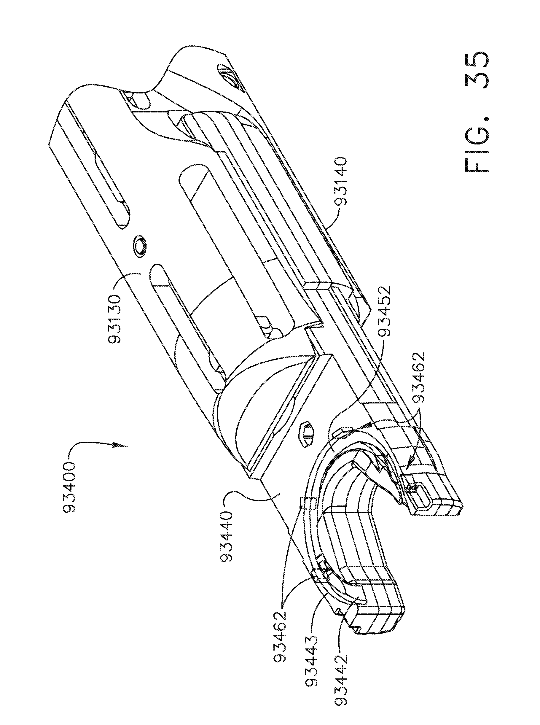
D00024

D00025

D00026
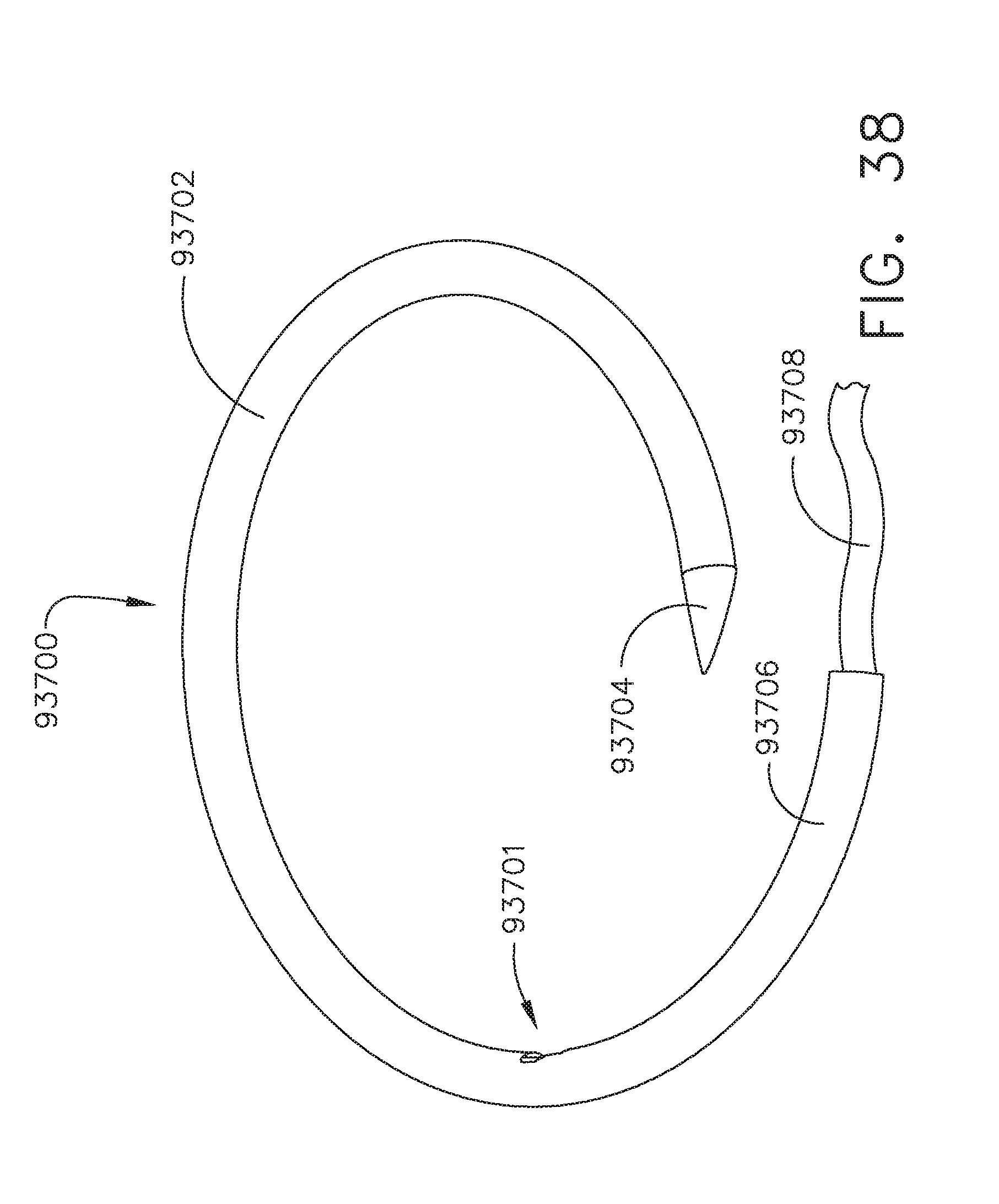
D00027

D00028
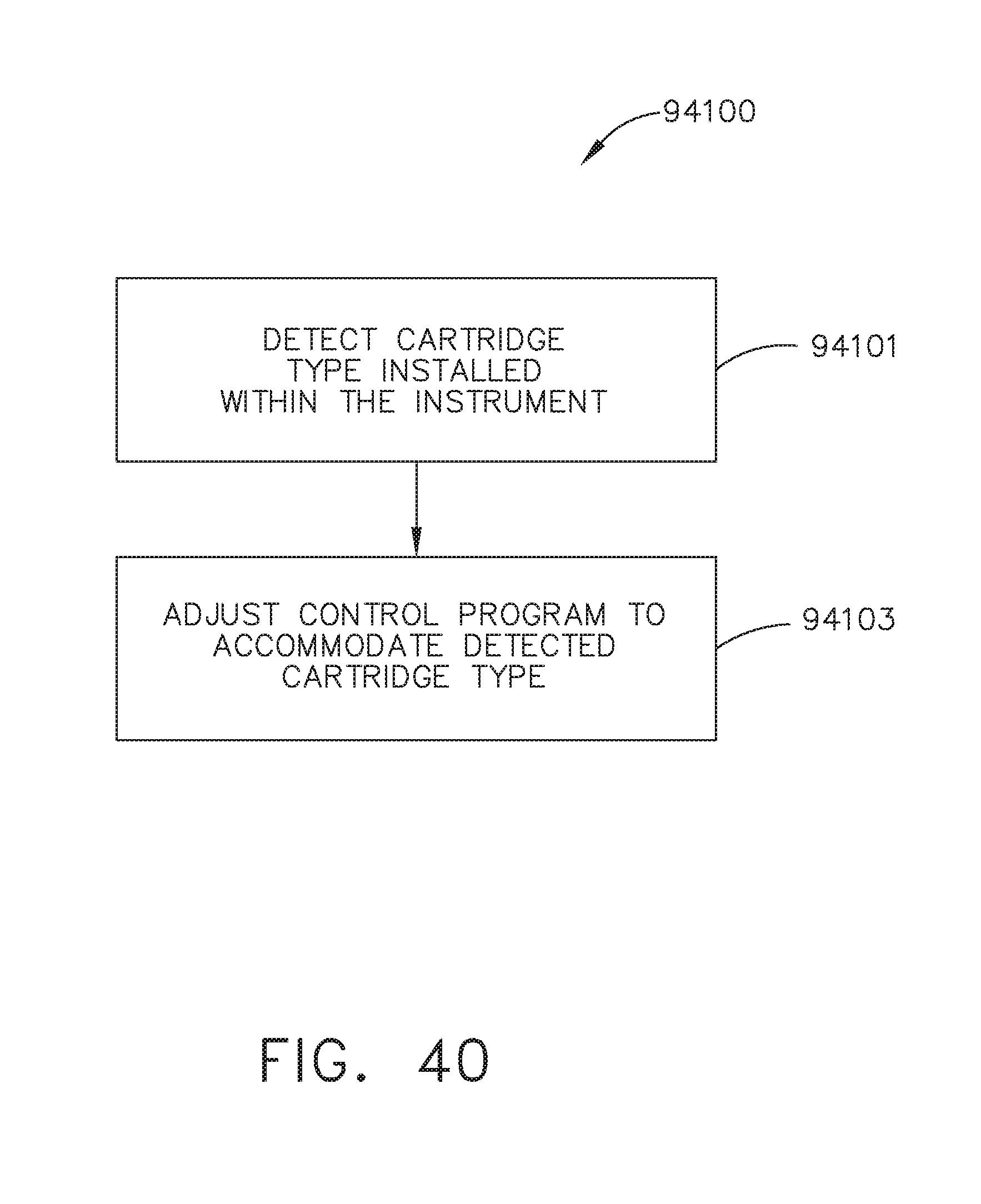
D00029

D00030
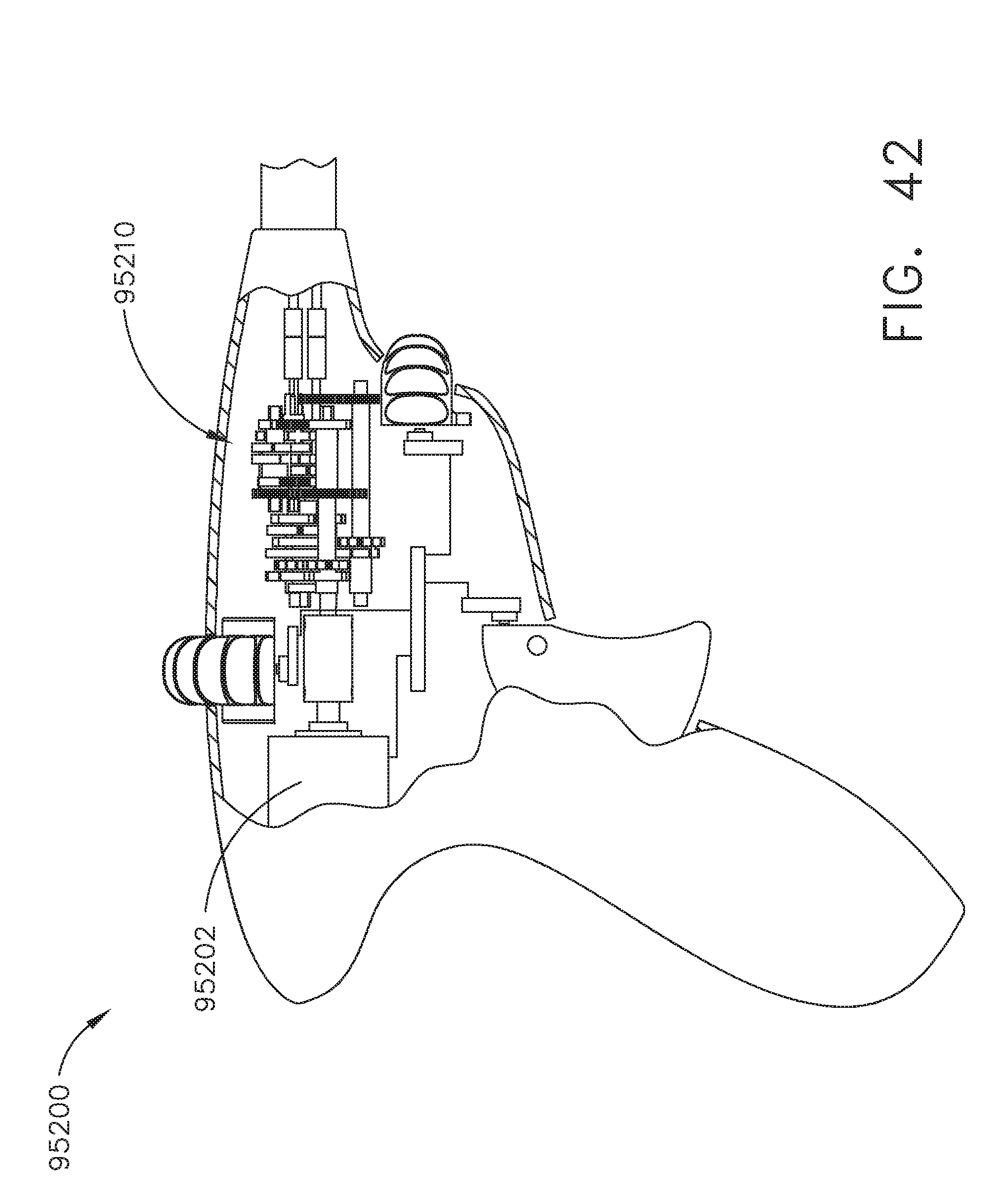
D00031

D00032

D00033

D00034

D00035

D00036

D00037
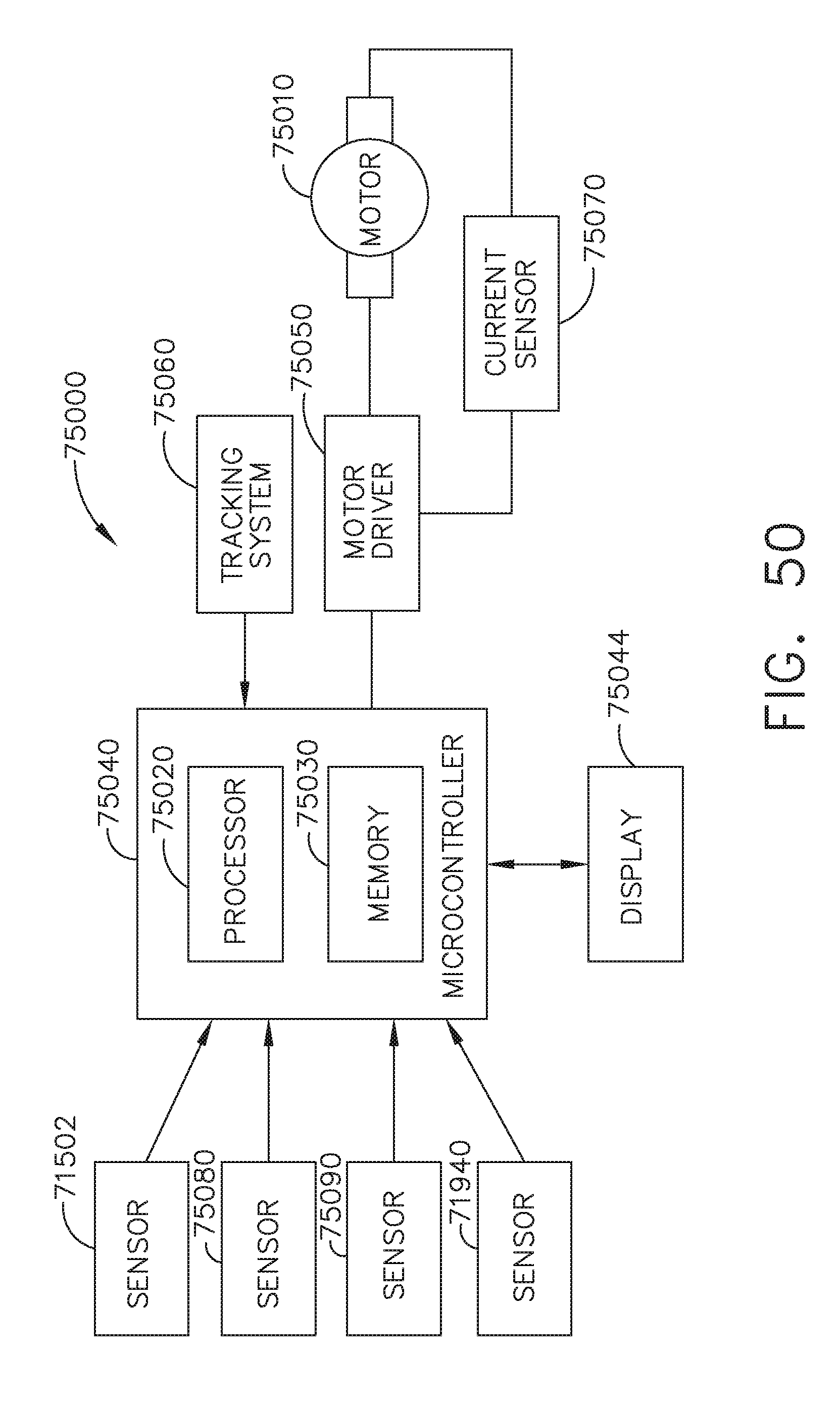
XML
uspto.report is an independent third-party trademark research tool that is not affiliated, endorsed, or sponsored by the United States Patent and Trademark Office (USPTO) or any other governmental organization. The information provided by uspto.report is based on publicly available data at the time of writing and is intended for informational purposes only.
While we strive to provide accurate and up-to-date information, we do not guarantee the accuracy, completeness, reliability, or suitability of the information displayed on this site. The use of this site is at your own risk. Any reliance you place on such information is therefore strictly at your own risk.
All official trademark data, including owner information, should be verified by visiting the official USPTO website at www.uspto.gov. This site is not intended to replace professional legal advice and should not be used as a substitute for consulting with a legal professional who is knowledgeable about trademark law.