Cosmetic Applicator
Kukreja; Shipra
U.S. patent application number 16/146546 was filed with the patent office on 2019-05-02 for cosmetic applicator. This patent application is currently assigned to HCT PACKAGING, INC.. The applicant listed for this patent is HCT PACKAGING, INC.. Invention is credited to Shipra Kukreja.
| Application Number | 20190125059 16/146546 |
| Document ID | / |
| Family ID | 66245301 |
| Filed Date | 2019-05-02 |


| United States Patent Application | 20190125059 |
| Kind Code | A1 |
| Kukreja; Shipra | May 2, 2019 |
COSMETIC APPLICATOR
Abstract
A cosmetic applicator for applying a cosmetic or care product includes an applicator head constructed from a thermal storage material. The applicator head is retained at a distal end of a stem. The applicator head comprises an applying member at a distal portion of the applicator head. The applying member includes at least one side face and an end face, and a longitudinal feed channel is disposed within the applying member. A distal end of the longitudinal feed channel opens to the end face of the applying body and defines an opening at the end face.
| Inventors: | Kukreja; Shipra; (New Delhi, IN) | ||||||||||
| Applicant: |
|
||||||||||
|---|---|---|---|---|---|---|---|---|---|---|---|
| Assignee: | HCT PACKAGING, INC. Bridgewater NJ |
||||||||||
| Family ID: | 66245301 | ||||||||||
| Appl. No.: | 16/146546 | ||||||||||
| Filed: | September 28, 2018 |
| Current U.S. Class: | 1/1 |
| Current CPC Class: | A45D 2200/155 20130101; A45D 40/264 20130101; A45D 34/045 20130101; A45D 34/046 20130101; A45D 34/043 20130101; A45D 2200/157 20130101; A45D 40/267 20130101; A45D 40/265 20130101 |
| International Class: | A45D 34/04 20060101 A45D034/04; A45D 40/26 20060101 A45D040/26 |
Foreign Application Data
| Date | Code | Application Number |
|---|---|---|
| Oct 29, 2017 | IN | 201711038344 |
Claims
1. A cosmetic applicator for applying a product to a surface, comprising: a stem having a proximal end and a distal end; and an applicator head connected to the distal end of the stem, a distal portion of the applicator head is formed as an applying member having at least one side face and a distal end face; the applicator head being constructed at least partially from a thermal storage material; wherein the applicator head defines: a channel extending longitudinally within the applicator head and having a distal end defining an opening in the distal end face of the applicator head; and an air vent extending from the side face of the applicator head to the channel.
2. The cosmetic applicator of claim 1, wherein the thermal storage material is ceramic, glass, stone, metal, or a metal alloy.
3. The cosmetic applicator of claim 1, wherein the channel has a closed proximal end within the applicator head.
4. The cosmetic applicator of claim 1, wherein the applicator head has a length and the channel extends over fifty percent of a length of the applying member of the applicator head.
5. The cosmetic applicator of claim 1, wherein the air vent extends transversely through the applicator head between opposing sides, the air vent intersecting the channel.
6. The cosmetic applicator of claim 1, wherein the air vent intersects the channel adjacent a proximal end of the channel.
7. The cosmetic applicator of claim 1, wherein the channel has a constant width along its length.
8. The cosmetic applicator of claim 1, wherein the distal end face of the applicator head is angled relative to a longitudinal axis of the applicator head.
9. The cosmetic applicator of claim 1, wherein the opening of the channel occupies less than fifty percent of a total surface area of the distal end face.
10. The cosmetic applicator of claim 1 wherein the channel has a first diameter, and the air vent has a second diameter, and the first diameter is greater than the second diameter.
11. The cosmetic applicator of claim 1, further comprising a cap connected to the proximal end of the stem.
12. A cosmetic package, comprising: a cosmetic applicator as in claim 11, and a receptacle for holding a cosmetic product, wherein the stem and applicator head are configured to be inserted into the receptacle and the cap is configured to releasably connect with an open end of the receptacle.
13. The cosmetic package of claim 12, further comprising a wiper disposed in a neck of the receptacle adjacent the open end, the wiper configured for wiping excess product from the applicator head while the applicator head is removed from the receptacle.
14. The cosmetic package of claim 12, wherein the receptacle lacks a wiper at the open end thereof.
15. A cosmetic package: a receptacle for holding a cosmetic product, the receptacle having a closed distal end and an open proximal end; an applicator configured to extend into the receptacle, the applicator including a stem having a proximal end and a distal end, an applicator head connected to the distal end of the stem, a distal portion of the applicator head is formed as an applying member having at least one side face and a distal end face, the applicator head defining a channel extending longitudinally within the applicator head and having a distal end defining an opening in the distal end face of the applicator head and an air vent extending from the side face of the applicator head to the channel, the applicator head being constructed at least partially from a thermal storage material; and a cap connected to the proximal end of the stem, the cap configured to releasably connect with the open proximal end of the receptacle.
16. The cosmetic package of claim 15, wherein the thermal storage material is ceramic, glass, stone, metal, or a metal alloy.
17. The cosmetic package of claim 15, wherein the channel has a first diameter, and the air vent has a second diameter, and the first diameter is greater than the second diameter.
18. The cosmetic package of claim 15, wherein the air vent extends transversely through the applicator head between opposing sides, the air vent intersecting the channel.
19. The cosmetic package of claim 15, wherein the air vent intersects the channel adjacent a proximal end of the channel.
20. A cosmetic applicator for applying a product to a surface, comprising: a stem having a proximal end and a distal end; an applicator head connected to the distal end of the stem, a distal portion of the applicator head is formed as an applying member having at least one side face and a distal end face; a channel extending longitudinally within the applicator head and having a distal end defining an opening in the distal end face of the applicator head and a proximal end which is closed within the applicator head; and an air vent extending from the side face of the applicator head to the channel.
Description
CROSS REFERENCE TO RELATED PATENT APPLICATIONS
[0001] The present application claims the benefit of and priority to Indian Patent Application Serial Number 201711038344, filed on Oct. 29, 2017, the disclosure of which is incorporated herein by reference.
TECHNICAL FIELD
[0002] Embodiments of the present disclosure generally relate to a cosmetic applicator for applying a flowable cosmetic or pharmaceutical product, in particular a liquid, viscous or semi-viscous liquid, an emulsion, a gel or a suspension, to a surface, in particular to a biological surface, for example skin or keratinous materials of the human body. More particularly, the present disclosure generally relates to a cosmetic applicator formed from a thermal storage material and including at least one feed channel.
BACKGROUND
[0003] Cosmetic applicators such as dip or wand applicators are known in the cosmetic industry. Cosmetic packages often include such applicators for dispensing a particular cosmetic contained in the package reservoir. The cosmetic applicator generally includes a stem with a cap at one end and an applicator head in the form of a brush, spatula or other applicator structure suitable for applying a cosmetic or a care product including viscous cosmetics, mascara, eye liner, lip gloss, hair color, wound care, skin care, under eye cosmetics, pharmaceutical and like products.
[0004] One such applicator is disclosed in U.S. Pat. No. 6,331,085 for applying and transporting a quantity of cosmetic product to a user's skin. The applicator comprises a generally cylindrical elastomeric tip with a long axis, the tip including a distal end portion having a distal extremity with at least one material-holding concavity formed therein, and said concavity having a rim.
[0005] Another U.S. Pat. No. 7,481,591 discloses an applicator comprising a rod and an application surface formed of a plurality of cones. These cones have a certain elasticity and movability and can therefore massage the cosmetic product, which is stored between the plurality of cones.
[0006] While such applicators are generally satisfactory, there still exists a need for a cosmetic applicator for applying a satisfactory amount of a cosmetic product to a biological surface and is able to provide a treatment, therapy, and/or sensation during use.
SUMMARY
[0007] According to an embodiment of the present disclosure, there is provided a cosmetic package comprising a cosmetic applicator for applying a product including a cosmetic or a care product. The cosmetic or care product includes viscous cosmetics, such as mascara, eyebrow stain, lip gloss, hair color, skin care, under eye cosmetics, pharmaceutical and like products.
[0008] According to an embodiment of the present disclosure, the applicator comprises an applicator head retained at a distal end of a stem for applying the product; and a cap at a proximal end of the stem.
[0009] According to an aspect of the present disclosure, the cosmetic package comprises a receptacle configured to contain the product and the cosmetic applicator. The applicator head is configured to be inserted into the receptacle so as to become loaded with the product and transport the product onto a surface where the product needs to be applied.
[0010] According to an aspect of the present disclosure, a wiper is inserted into a neck of the receptacle for wiping off excess product from the cosmetic applicator while the cosmetic applicator is being removed from the receptacle.
[0011] According to another aspect of the present disclosure, the cap of the cosmetic applicator has threads which can be screwed onto threads formed on the neck of the receptacle.
[0012] According to yet another aspect of the present disclosure, the distal end of the stem includes an interior longitudinal cavity for receiving and retaining the applicator head.
[0013] According to yet another aspect of the present disclosure, the applicator head is constructed, at least partially, from a thermal storage material that is capable of retaining heat or cold for application. The thermal storage material may comprise, for example, a metal, ceramic, glass, stone, alloy and/or other material with a relatively high thermal storage capacity and/or thermal conductivity.
[0014] According to yet another aspect of the present disclosure, the applicator head has a body comprising a proximal portion and a distal portion. The proximal end portion of the applicator head is formed as shank which is configured to be received and retained within a longitudinal cavity of the stem in a mating relationship. The distal portion of the applicator head is formed as an applying member that is used for applying the cosmetic product to a target biological surface. The applying member of the applicator head further includes at least one side face and an end face.
[0015] In an embodiment of the present disclosure, the applying member of the applicator head further includes at least one curved side face and an end face. The applying member of the applicator head further includes a curved applicator tip with the end face disposed at a given non-zero angle relative to a central longitudinal axis of the applicator head. More specifically, the end face of the applicator head is inclined with respect to a central longitudinal axis of the applicator head. In this embodiment, that angle is approximately 45 degrees but in alternate embodiments the end face may be at any other angle with respect to the central longitudinal axis of the applicator head. The presence of an inclined end face enables the applicator head to be used with different contact areas. In particular, the product can be applied more quickly while restricting the number of applications. It will be appreciated that the angle of the end face may vary within the scope of the invention depending on, for instance, the type of cosmetic material to be applied, the goals of the manufacturer and user, and other factors. As an example, a steeper angle will provide a greater surface area and will consequently permit the retention of more cosmetic product. The inclined end face of the applicator head may also be slightly concavely or convexly curved.
[0016] According to yet another aspect of the present disclosure, the applicator head comprises a longitudinal feed channel disposed within the applicator head. A distal end of the longitudinal feed channel opens to the end face of the applicator head, defining an opening at the end face of the applicator head. The longitudinal feed channel makes it possible to fill the applicator head, which thus serves as cosmetic product reserve or a capillary reservoir. In other words, applying member holds the cosmetic product substantially within the longitudinal feed channel via capillary attraction. Furthermore, the cosmetic product reserve is delivered only when the end face including the opening of the longitudinal feed channel is applied to a biological surface to be treated, for example, to surface of the nail or skin to be cared for or treated. The dose of the cosmetic product to be delivered depends on the viscosity of the product to be delivered and on the dimensions of the longitudinal feed channel. Thus, by altering its width, depth and length, it is possible to deliver exactly the required dose of product depending on its viscosity. It is to be noted that the longitudinal feed-channel has same width throughout its length, however in alternate embodiments, the width of the longitudinal feed-channel may vary along its length.
[0017] According to yet another aspect of the present disclosure, the longitudinal feed channel may or may not be concentric with the body of the applicator head.
[0018] According to yet another aspect of the present disclosure, when the applicator head is lowered into the cosmetic product contained in the receptacle, the longitudinal feed channel becomes charged with the cosmetic product forming said capillary reservoir of the cosmetic product within the longitudinal feed channel of the applicator head. When the cosmetic applicator is separated from the associated receptacle, the longitudinal feed channel of the applicator head remains charged with the cosmetic product.
[0019] According to yet another aspect of the present disclosure, the longitudinal feed channel of the applicator head extends over fifty percent of the length of the applying member of the applicator head.
[0020] According to yet another aspect of the present disclosure, longitudinal feed channel of the applicator head is constructed from a thermal storage material, such as metal, ceramic, glass, or other material which is capable of retaining and conducting heat or cold for application to a body.
[0021] According to yet another aspect of the present disclosure, the applying member of the applicator head is provided with an air-vent which communicates with longitudinal feed channel by intersecting the longitudinal feed channel adjacent a proximal end of the longitudinal feed channel. In some examples, the longitudinal feed channel has a first diameter, and the air vent has a second diameter, the first diameter being greater than the second diameter. Such a difference in diameters may be useful, for example, to allow a cosmetic product to remain in the longitudinal feed channel without escaping via the air vent. The difference in diameters may further facilitate the cosmetic product being drawn out using the capillary action described below. In other examples, the air vent and longitudinal feed channel have the same diameter.
[0022] According to another embodiment, the air-vent transversally intersects the longitudinal feed channel at a proximal portion of the longitudinal feed channel. In alternate embodiments, the air vent may intersect the longitudinal feed channel at right angle or any other angle. The transverse air-vent has two diametrically opposing openings at the at least one curved side face of the applicator head. The air is admitted to the longitudinal feed channel and hence to the capillary reservoir formed in the longitudinal feed channel through the openings of the air vent. When the end face of the applicator head is moved over the surface to be treated, sufficient air is admitted to the capillary reservoir through the air vent and the cosmetic product is compelled to pass through this longitudinal feed channel thereby insuring an even and uniform flow of the cosmetic product to the end face. It will thus be seen that the openings of the air vent and the longitudinal feed-channel automatically regulate the flow of the cosmetic product to the end face of the applicator head from the capillary reservoir, this being due to the fact that the partial vacuum in the capillary reservoir of the longitudinal feed channel is caused by the initial discharge of the cosmetic product which permits the air to pass through the openings of the air vent to said capillary reservoir.
[0023] According to another embodiment of the present disclosure, the applicator head has the opening of the longitudinal feed channel at the end face of the applicator head and the opening being slanted/inclined. More particularly, the opening is a substantially oval opening. In other words, the opening is oriented in a plane which is oblique with respect to the central longitudinal axis of the applicator head. In variant embodiments, the opening may have any other desirable shape, circular, spatulate, obviate, elliptic, oblong, deltoid for example.
[0024] According to another embodiment of the present disclosure, the end face of the applicator head is inclined with respect to a central longitudinal axis of the applicator head and extends over at least one-fifth of the length of the applying member of the applicator head. In another embodiment of the present disclosure, however, the end face of the applicator head extends over at least half a length of the applying member of the applicator head, thus providing a larger contact area during application.
[0025] According to one embodiment of the present disclosure, the opening of the longitudinal feed channel at the end face of the applicator head occupies less than 50% of a total surface area of the end face.
[0026] According to another embodiment of the present disclosure, the opening of the longitudinal feed channel at the end face of the applicator head occupies more than 50% of a total surface area of the end face. In some examples, the opening of the longitudinal feed channel at the end face of the applicator head occupies more than 80% of a total surface area of the end face of the applicator head.
[0027] In some of the embodiments of the present disclosure, the at least one side face of the applying member comprises a constricted side face portion providing a neck like portion in the applying portion.
[0028] According to an aspect of the present disclosure, at least a portion of an outer surface of the applying member of the applicator head may be flocked.
[0029] According to another aspect of the present disclosure, the applicator head may be of any other desirable shape.
[0030] According to another aspect of the present disclosure, the proximal end portion of the applicator head is formed as a shank which is configured to be received and retained within a longitudinal cavity of the stem in a mating relationship. The applicator head and the stem may be fit together by friction fit, snap fit, by gluing, crimping, magnetic engagement and any other suitable means known in the art.
[0031] In variant embodiments, outer surface of the applying member may include projections, ribs, grooves, discs, slits, cuts, holes, dimples, or other surface features or surface treatments (e.g., abrading) that are suitable for loading, transporting and applying cosmetic product.
[0032] According to another aspect of the present disclosure, the receptacle may be polypropylene, while the cap and the stem may be formed of acrylonitrile butadiene styrene or any other suitable polymeric material. The stem may be formed of polyacetal or any other suitable polymeric material.
[0033] The material for forming a wiper may be low-density polyethylene, foam, sponge, sintered block, aggregate of natural or synthetic fibers, woven or non-woven fibers, plastic, or a combination of such materials. The aforementioned materials for forming various parts of the package of the present disclosure are an example, however other suitable materials may also be used.
[0034] The above and other objects, features and advantages of the present disclosure will become clear from the following description when the same is read in conjunction with the accompanying drawings.
BRIEF DESCRIPTION OF THE DRAWINGS
[0035] So that the manner in which the above recited features of the present disclosure can be understood in detail, a more particular description of the disclosure, briefly summarized above, may be had by reference to embodiments, some of which are illustrated in the appended drawings.
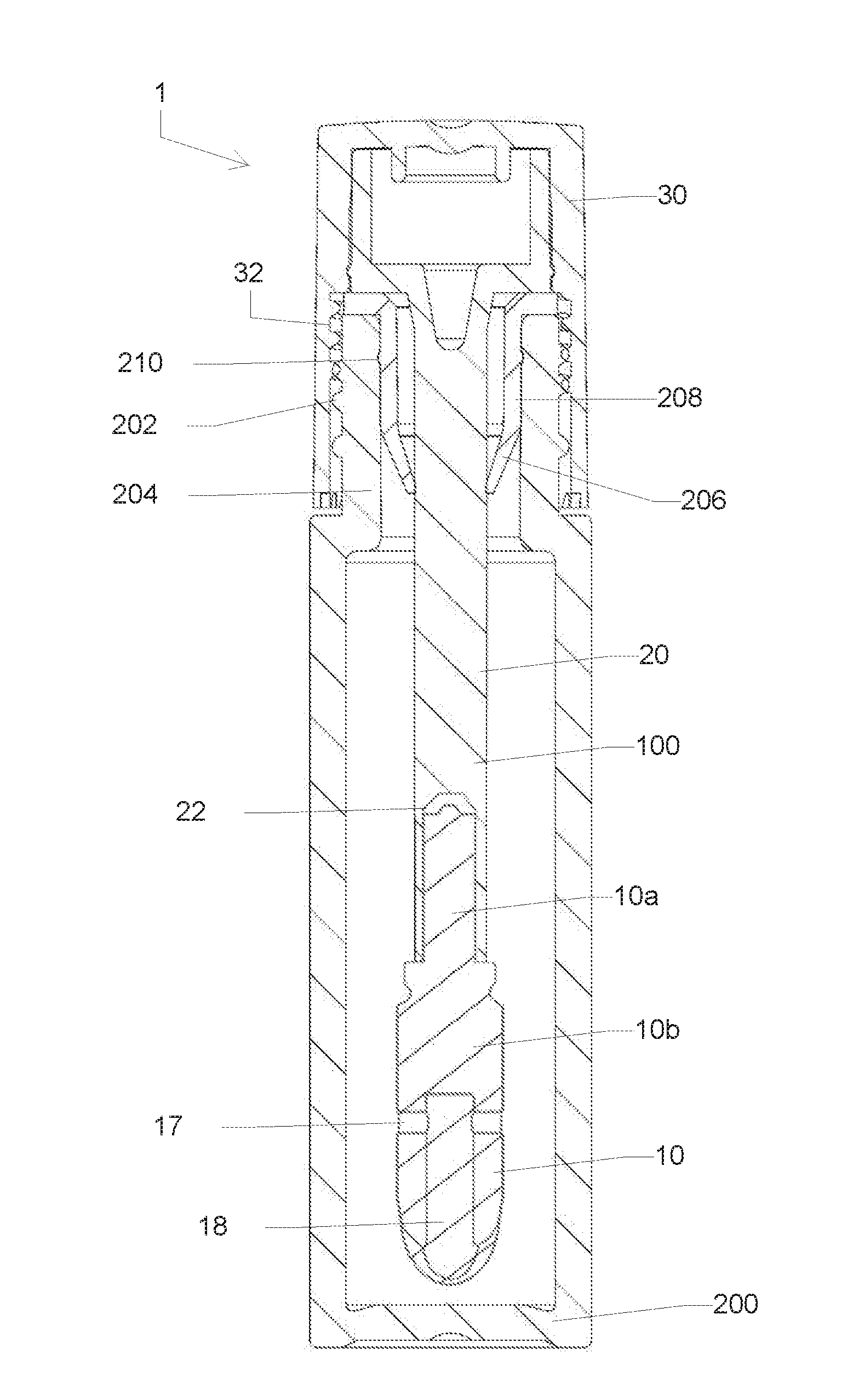
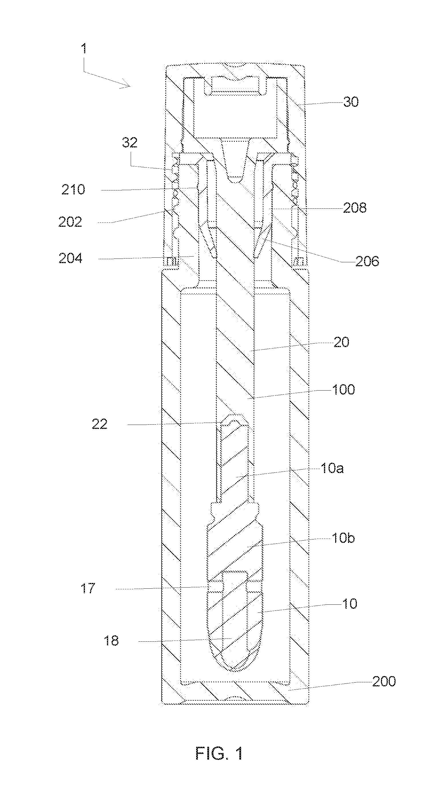
[0036] FIG. 1 shows a longitudinal cross-sectional view of a cosmetic package comprising a cosmetic applicator of present disclosure;
[0037] FIG. 2 shows an isometric view of an applicator head of FIG. 1;
[0038] FIG. 3 shows a front view of the applicator head of FIG. 2;
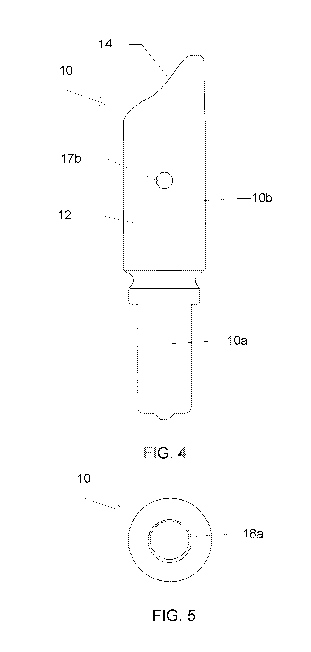
[0039] FIG. 4 shows a side view of the applicator head of FIG. 2;
[0040] FIG. 5 shows a bottom view of the applicator head of FIG. 2;
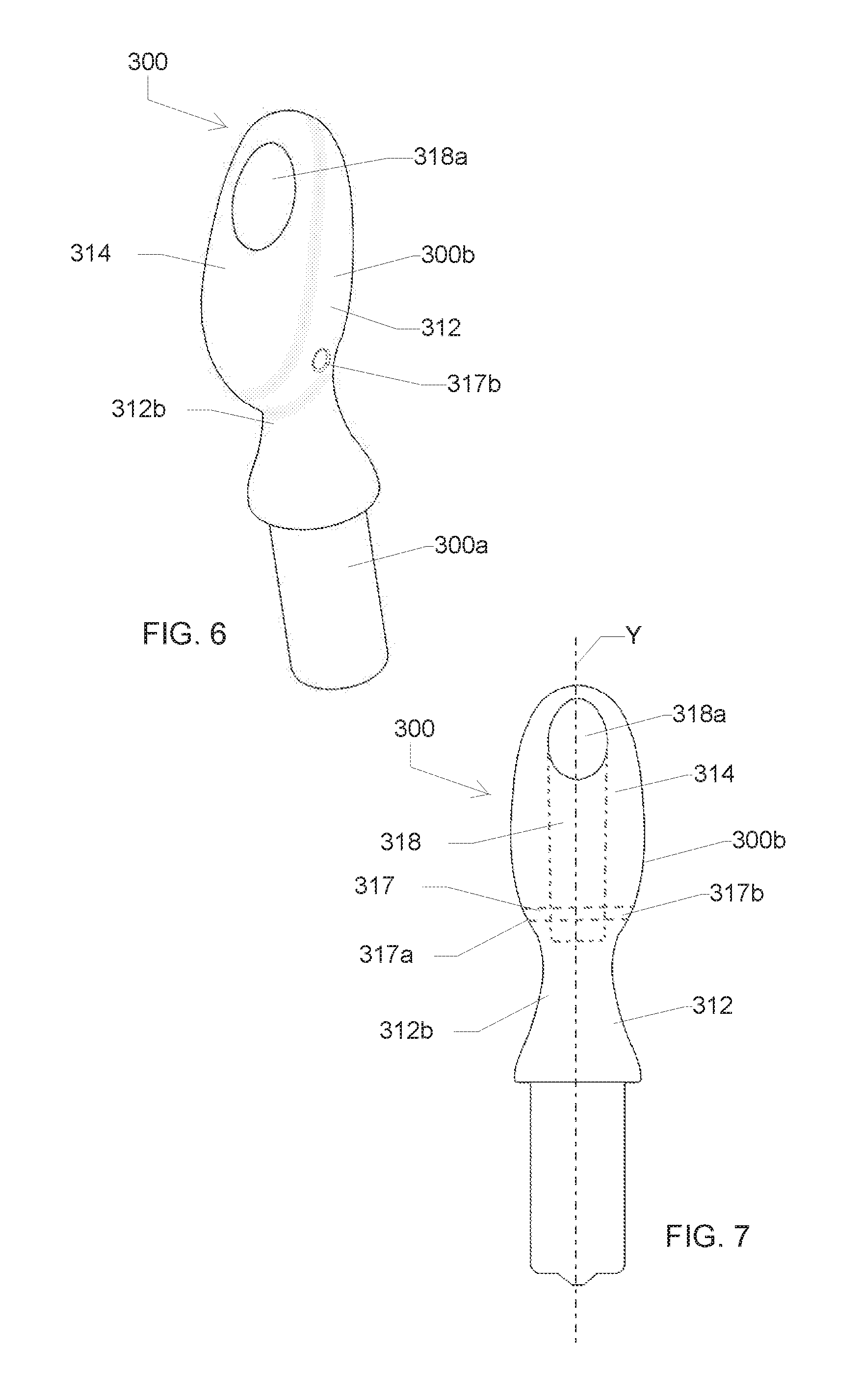
[0041] FIG. 6 shows an isometric view of an applicator head according to a second embodiment of the present disclosure;
[0042] FIG. 7 shows a front view of the applicator head of FIG. 6;
[0043] FIG. 8 shows a side view of the applicator head of FIG. 6;
[0044] FIG. 9 shows a bottom view of the applicator head of FIG. 6;
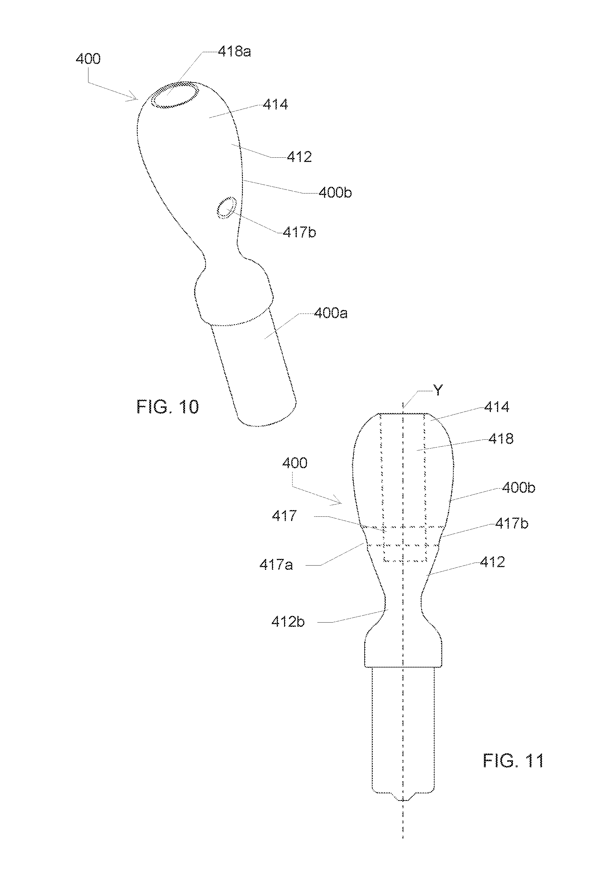
[0045] FIG. 10 shows an isometric view of an applicator head according to a third embodiment of the present disclosure;
[0046] FIG. 11 shows a front view of the applicator head of FIG. 10;
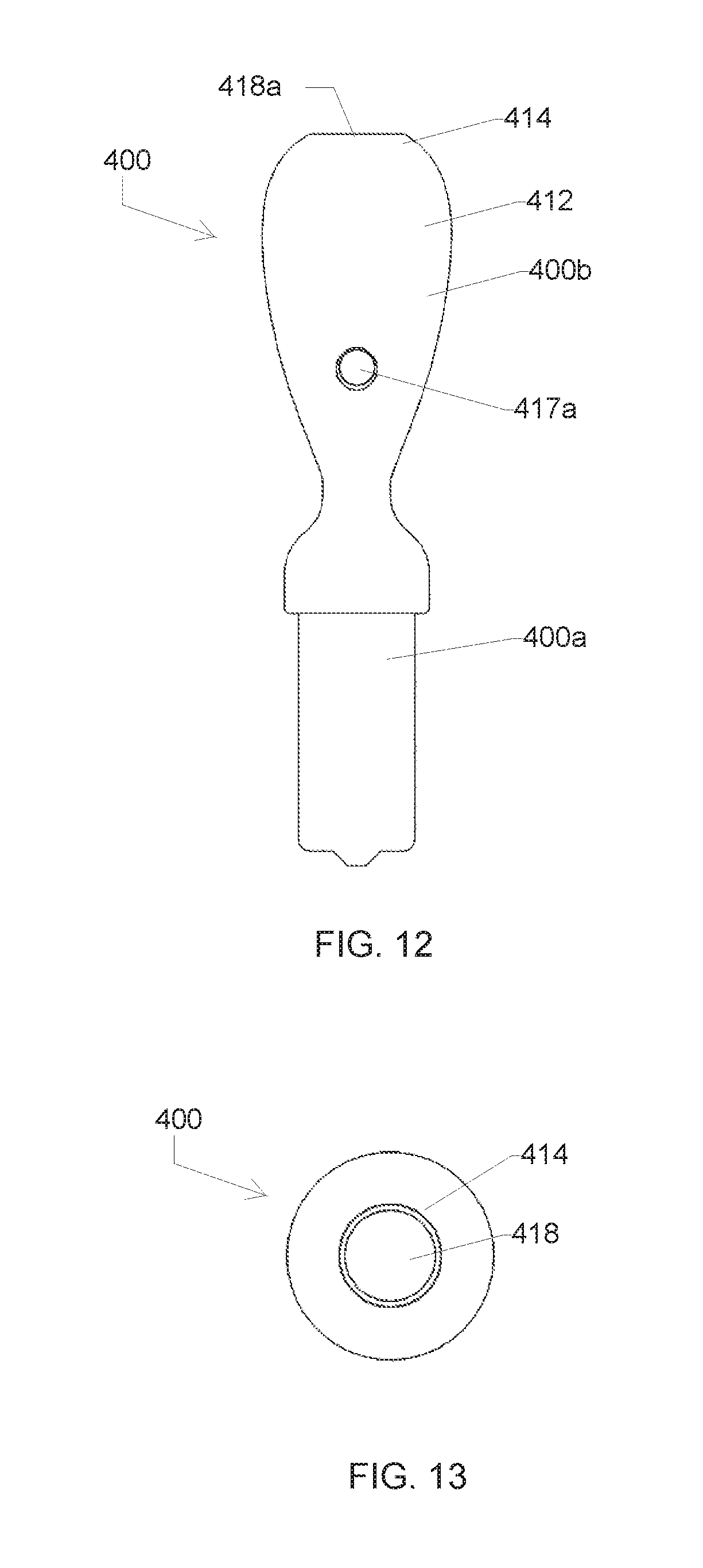
[0047] FIG. 12 shows a side view of the applicator head of FIG. 10; and
[0048] FIG. 13 shows a bottom view of the applicator head of FIG. 10.
[0049] To facilitate understanding, identical reference numerals have been used, where possible, to designate identical elements that are common to the figures. It is to be noted, however, that the appended drawings illustrate only typical embodiments of this disclosure and are therefore not to be considered limiting of its scope, for the disclosure may admit to other equally effective embodiments.
DETAILED DESCRIPTION
[0050] Throughout this specification, the terms "comprise," "comprises," "comprising" and the like, shall consistently mean that a collection of objects is not limited to those objects specifically recited.
[0051] FIG. 1 illustrates a longitudinal sectional view of a cosmetic package 1. The cosmetic package 1 comprises a receptacle 200 for holding a cosmetic product (not shown) and a cosmetic applicator 100. The cosmetic applicator 100 comprises an applicator head 10, a stem 20 and a cap 30. The cosmetic applicator 100 according to one embodiment of the disclosure, may be used to apply the product (not shown) including a cosmetic or a care product. The cosmetic or care product includes viscous, semi-viscous or liquid cosmetics, mascara, lip gloss, hair color, skin care, under eye cosmetics, pharmaceutical and like products.
[0052] The cap 30 of the cosmetic applicator 100 has threads 32 which can be, during period of non-use, screwed onto threads 202, formed on a neck 204 of the receptacle 200.
[0053] In the example shown in FIG. 1, inserted in the neck 204 of the receptacle 200 is a wiper 206 for wiping off excess product from the applicator 100. The wiper 206 also comprises an annular bead 208 for engaging into a corresponding annular groove 210 on the inside of the neck 204 of the receptacle 200. In other examples, the neck 204 of the receptacle 200 is devoid of any wiper structure. In such an example, any excess product may be drained as the applicator 100 is removed from the receptacle 200. Alternatively, the applicator head 10 may be pressed or wiped against the inside surface of the neck 204 as the applicator 100 is removed from the receptacle 200.
[0054] As shown in FIG. 1, the cap 30 is retained at a proximal end of the stem 20 for gripping, and the applicator head 10 is retained at a distal end of the stem 20 for applying the cosmetic product. The applicator head 10 in this example is constructed, at least partially, from a thermal storage material that is capable of retaining heat or cold for application. The thermal storage material may comprise, for example, a metal, ceramic, glass, stone, alloy and/or other material with a relatively high thermal storage capacity and/or thermal conductivity.
[0055] According to an exemplary first embodiment shown in FIGS. 2-5, the applicator head 10 has a body comprising a proximal portion 10a and a distal portion 10b. In the present embodiment, the applicator head 10 is substantially cylindrical in shape, in alternate embodiments, the applicator head 10 may be of any other desirable shape.
[0056] Referring to FIGS. 2 to 4, the proximal end portion 10a of the applicator head 10 is formed as shank 10a which is configured to be received and retained within a longitudinal cavity 22 of the stem 20 in a mating relationship (see FIG. 1).
[0057] The applicator head 10 and the stem 20 may be fit together by friction fit, snap fit, by gluing, crimping, magnetic engagement and any other suitable means known in the art. In an exemplary embodiment as shown in FIG. 1, the applicator head 10 and the stem 20 are fitted together by friction fitment.
[0058] Referring to FIGS. 1-4, the distal portion 10b of the applicator head 10 is an applying member 10b which includes at least one side face 12 and a distal end face 14. In this example, the applicator head 10 has a curved applicator tip 16 with the end face 14 disposed at a given angle relative to a central longitudinal axis X of the applicator head 10. The presence of an inclined end face 14 enables the applicator head 10 to be used with different contact areas. In particular the product can be applied more quickly while restricting the number of applications. In this example, that angle is approximately 45 degrees. It will be appreciated that the angle of the end face 14 may vary within the scope of the invention depending on, for instance, the type of cosmetic material to be applied, the goals of the manufacturer and user, and other factors. As an example, a steeper angle will provide a greater surface area and will consequently permit the retention of more cosmetic product. The at least one side face 12 of the applicator head 10 is curved because of a cylindrical body of the applying member 10b.
[0059] As can be appreciated by reference to FIG. 3, the applicator head 10 comprises a longitudinal feed channel 18 disposed within the applicator head 10 which is concentric with the cylindrical body of the applicator head 10a. A distal end of the longitudinal feed channel 18 opens to the end face 14, defining an opening 18a at the end face 14. The longitudinal feed channel 18 serves as cosmetic product reserve or a capillary reservoir. In other words, the applying member 10 holds the cosmetic product substantially within the longitudinal feed channel 18 via capillary attraction. Furthermore, the cosmetic product reserve is delivered only when the end face 14 including the opening 18a is applied to a biological surface to be treated, for example, to surface of the nail or skin to be cared for or treated. The dose of the cosmetic product to be delivered depends on the viscosity of the product to be delivered and on the dimensions of the longitudinal feed channel 18. Thus, by altering its width, depth and length, it is possible to deliver exactly the required dose of product depending on its viscosity. It is to be noted that the longitudinal feed-channel 18 illustrated in FIG. 3 has the same width throughout its length. In alternate embodiments, the width of the longitudinal feed-channel 18 may vary along its length.
[0060] When the applicator head 10 is lowered into the cosmetic product contained in the receptacle 200, the longitudinal feed channel 18 becomes charged with the cosmetic product forming said capillary reservoir of the cosmetic product within the longitudinal feed channel 18 of the applicator head 10. When the cosmetic applicator 100 is separated from the associated receptacle 200, the longitudinal feed channel 18 of the applicator head 10 remains charged with the cosmetic product. Here, the longitudinal feed channel 18 is generally concentric with the applying member 10a of the applicator head 10, but non-concentric dispositions are possible within the scope of the disclosure.
[0061] Referring to FIG. 3, the applicator head 10 is provided with an air-vent 17 which communicates with the longitudinal channel 18 adjacent a proximal end of the longitudinal feed channel 18, i.e. air-vent 17 intersects at the proximal end of the longitudinal feed channel 18. The air-vent 17 may transversally intersect the longitudinal feed channel 18 at the proximal end of the longitudinal feed channel 18, as illustrated in FIG. 3. In other embodiments, the air-vent 17 may intersect the longitudinal feed channel 18 at a non-perpendicular angle. The transverse air-vent 17 has two diametrically opposing openings 17a, 17b present at the cylindrical side face 12 of the applicator head 10. The air is admitted to the longitudinal feed channel 18 and hence to the capillary reservoir formed in the longitudinal feed channel 18 through the openings 17a, 17b of the longitudinal vent or passage 17. When the end face 14 of the applicator head 10 is moved over the surface to be treated, sufficient air is admitted to the capillary reservoir through the air vent 17 and the cosmetic product is compelled to pass through this longitudinal feed channel 18 thereby insuring an even and uniform flow of the cosmetic product to the end face 14.
[0062] In some examples, the longitudinal feed channel 18 has a first diameter, and the air vent has a second diameter, the first diameter being greater than the second diameter. Such a difference in diameters may be useful, for example, to allow a cosmetic product to remain in the longitudinal feed channel without escaping via the air vent. The difference in diameters may further facilitate the cosmetic product being drawn out using the capillary action described below. In other examples, the air vent and longitudinal feed channel have the same diameter.
[0063] It will thus be seen that the openings 17a, 17b of the air vent 17 and the feed-channel 18 automatically regulate the flow of cosmetic product to the end face 14 of the applicator head 10 from the capillary reservoir, this being due to the fact that the partial vacuum in the capillary reservoir of the feed channel 18 is caused by the initial discharge of the cosmetic product which permits the air to pass through the openings 17a, 17b to said capillary reservoir.
[0064] According to an aspect of the present embodiment, the longitudinal feed channel 18 extends over fifty percent of the length of the applying member 10b of the applicator head including the curved tip 16, see FIG. 3. In other embodiments, the longitudinal feed channel 18 extends over less than fifty percent, or over the entirety of the length of the applying member 10b of the applicator head, including the curved tip 16.
[0065] The longitudinal feed channel 18 is constructed from a thermal storage material, such as metal, ceramic, glass, or other material which is capable of retaining and conducting heat or cold for application to a body.
[0066] The applicator head 10 may be designed/configured to retain cosmetic product not only relative to the large surface area presented by the side face 12 of the applying member 10b, the applicator tip 16, and the end face 14, but also within the feed channel 18. With this, the cosmetic product can be successfully applied to a user's body with fewer required insertions of the applicator 100 into the open inner volume of the receptacle 200. Additionally, the surface contouring and surface variations provided by the cylindrical side face 12, the curved applicator tip 16, and the end face 14 can enable cosmetic to be applied with varying characteristics according to the user's goals.
[0067] According to another aspect of the present embodiment and as shown in FIGS. 2-4, the applicator head has the opening 18a at the end face 14 being slanted. More particularly, the opening 18a is a substantially oval opening. In other words, the opening 18a is oriented in a plane which is oblique with respect to a longitudinal axis X of the applicator head 10. In variant embodiments, the opening 18a may have any other desirable shape, spatulate, obviate, elliptic, oblong, deltoid for example.
[0068] Referring to FIGS. 6-9, these figures show an applicator head 300 according to a second embodiment of the present disclosure. Similar to the applicator head 10, the applicator head 300 is also made up from a thermal storage material selected from a group of a metal, ceramic, glass, stone, alloy and/or combinations thereof. The applicator head 300 differs from the applicator head 10 in respect to shape of the applying member as explained herein. An applying member 300b of the applicator head 300 includes an end face 314 and at least one curved side face 312. The end face 314 is inclined with respect to a longitudinal axis Y of the applicator head 300 and extends over at least half a length of the applying member 300b, thus providing a larger contact area during application. The applying member 300b includes a longitudinal feed channel 318 disposed within the applicator head 300, and wherein a distal end of the longitudinal feed channel 318 opens to the end face 314, defining an opening 318a at the end face 314. The opening 318a of the longitudinal feed channel 318 occupies less than 50% of a total surface area of the end face 314. The applying member 300b is provided with a transverse air-vent 317 which communicates with longitudinal feed channel 318 adjacent a proximal end of the longitudinal feed channel 318. In other embodiments, the air-vent 317 may intersect the longitudinal feed channel 318 at a non-perpendicular angle. The transverse air-vent 17 has two diametrically opposing openings 317a, 317b present at the side face 312 of the applying member 300b. Further, the at least one curved side face 312 of the applying member 300b comprises a constricted side face portion 312b providing a neck like appearance.
[0069] Referring to FIGS. 10-13, these views show an applicator head 400 according to a third embodiment of the present disclosure. Similar to the applicator head 10, the applicator head 400 is also made up from a thermal storage material selected from a group of a metal, ceramic, glass, stone, alloy and/or combinations thereof. The applicator head 400 differs from the applicator head 10 in respect to shape of the applying member as explained herein. An applying member 400b of the applicator head 400 is spheroid or ovoid in shape and includes a distal end face 414 and at least one curved side face 412. The end face 414 is at a non-zero angle with respect to a central longitudinal axis Y of the applicator head 300, more particularly the end face 414 forms 90 degree angle with respect to the central longitudinal axis Y of the applicator head 400. The applying member 400b includes a longitudinal feed channel 418 disposed within the applicator head 400, and wherein a distal end of the longitudinal feed channel 418 opens to the end face 414, defining an opening 418a at the end face 414. In some examples, the opening 418a of the longitudinal feed channel 418 occupies more than 50% of a total surface area of the end face 414. In other examples, the opening 418a occupies more than 80% of the total surface area of the end face 414 as seen in the FIG. 10. The applying member 400b is provided with a transverse air-vent 417 which communicates with the longitudinal channel 418 adjacent a proximal end of the longitudinal feed channel 418. In other embodiments, the air-vent 417 may intersect the longitudinal feed channel 418 at a non-perpendicular angle. The transverse air-vent 417 has two diametrically opposing openings 417a, 417b present at the side face 412 of the applying member 400b. The at least one side face 412 of the applying member 400b comprises a constricted side face portion 412b providing a neck like appearance. Since, the opening 418a of the longitudinal feed channel 418 occupies more than 50% or more than 80% of a total surface area of the end face 414, the user may use end face 414 only to dispense the product out from longitudinal feed channel 418 and spread it using curved side face 412.
[0070] According to an aspect of the present embodiment, at least a portion of an outer surface of the applicator head 10, 300, 400 may be flocked.
[0071] According to an aspect of the present embodiment, when the applicator head 10, 300, 400 is withdrawn from the receptacle 200, the wiper 206 cleans the applicator head 10, 300, 400 in a manner such that a minimal amount of product is retained on the side face 12, 312, 412. In embodiments in which the receptacle 200 is devoid of any wiper structure, any excess product may be drained from the applicator head 10, 300, 400 as it is withdrawn from the receptacle 200.
[0072] However, in a variant embodiment, the outer surface of the applying member 10b, 300b, 400b may include projections, ribs, grooves, discs, slits, cuts, holes, dimples, or other surface features or surface treatments (e.g., abrading) that are suitable for loading, transporting and applying cosmetic product.
[0073] The receptacle may be made of, for example, be polypropylene while the cap and the stem may be formed of acrylonitrile butadiene styrene or any other suitable polymeric material. The stem may be formed of polyacetal or any other suitable polymeric material.
[0074] The material for forming the wiper, if present, may be low-density polyethylene, foam, sponge, sintered block, aggregate of natural or synthetic fibers, woven or non-woven fibers, plastic, or a combination of such materials. The aforementioned materials for forming various parts of the package of the present disclosure are an example, however other suitable materials may also be used.
[0075] It will be understood that the foregoing is only illustrative of the principles of the disclosure, and that various modifications can be made by those skilled in the art without departing from the scope and spirit of the disclosure. For example, the shapes and/or sizes of various components can be different from the shapes and sizes shown herein. As another example, the materials used for various components can be different from those mentioned specifically herein.
* * * * *
D00000
D00001
D00002
D00003
D00004
D00005
D00006
D00007
XML
uspto.report is an independent third-party trademark research tool that is not affiliated, endorsed, or sponsored by the United States Patent and Trademark Office (USPTO) or any other governmental organization. The information provided by uspto.report is based on publicly available data at the time of writing and is intended for informational purposes only.
While we strive to provide accurate and up-to-date information, we do not guarantee the accuracy, completeness, reliability, or suitability of the information displayed on this site. The use of this site is at your own risk. Any reliance you place on such information is therefore strictly at your own risk.
All official trademark data, including owner information, should be verified by visiting the official USPTO website at www.uspto.gov. This site is not intended to replace professional legal advice and should not be used as a substitute for consulting with a legal professional who is knowledgeable about trademark law.