Atomizing Head, Atomizer And An Electronic Cigarette Thereof
QIU; Weihua
U.S. patent application number 16/232800 was filed with the patent office on 2019-05-02 for atomizing head, atomizer and an electronic cigarette thereof. The applicant listed for this patent is Joyetech Europe Holding GmbH. Invention is credited to Weihua QIU.
| Application Number | 20190124994 16/232800 |
| Document ID | / |
| Family ID | 57213510 |
| Filed Date | 2019-05-02 |


| United States Patent Application | 20190124994 |
| Kind Code | A1 |
| QIU; Weihua | May 2, 2019 |
ATOMIZING HEAD, ATOMIZER AND AN ELECTRONIC CIGARETTE THEREOF
Abstract
An atomizing head includes an atomizing head sleeve having an atomizing chamber therein, an atomizing assembly, and a separator. One end of the atomizing head sleeve has a vent in communication with the atomizing chamber. The atomizing assembly is received in the atomizing chamber. The atomizing assembly includes heating element, the separator isolates the air vent to form an air inlet and an air outlet. The outside air enters the atomizing chamber through the air inlet, and across through or flow through the entire heating element, and then flows out through the air outlet. The vents of the atomizing heads are separated by the separator to form the air inlet and the air outlet. The air inlet and the air outlet are in communication with the inside chamber of the heating elements in the atomizing assemblies.
| Inventors: | QIU; Weihua; (Changzhou, CN) | ||||||||||
| Applicant: |
|
||||||||||
|---|---|---|---|---|---|---|---|---|---|---|---|
| Family ID: | 57213510 | ||||||||||
| Appl. No.: | 16/232800 | ||||||||||
| Filed: | December 26, 2018 |
Related U.S. Patent Documents
| Application Number | Filing Date | Patent Number | ||
|---|---|---|---|---|
| PCT/CN2017/082806 | May 3, 2017 | |||
| 16232800 | ||||
| Current U.S. Class: | 1/1 |
| Current CPC Class: | A24F 47/008 20130101 |
| International Class: | A24F 47/00 20060101 A24F047/00 |
Foreign Application Data
| Date | Code | Application Number |
|---|---|---|
| Jun 28, 2016 | CN | 201610483728.3 |
Claims
1. An atomizing head, comprising: an atomizing head sleeve having an atomizing chamber therein, one end of the atomizing head sleeve provided with a vent in communication with the atomizing chamber; an atomizing assembly received in the atomizing chamber, the atomizing assembly comprises heating element, and a separator isolates the air vent to form an air inlet and an air outlet, the outside air enters the atomizing chamber through the air inlet, and across through or flow through the entire heating element, and then flows out through the air outlet.
2. The atomizing head according to claim 1, wherein the air inlet and the air outlet is in communication with each other through the inner cavity of the heating element, the external airflow flows in the atomizing head through the air inlet, pass through the entire heating element, and flows out through the air outlet.
3. The atomizing head according to claim 1, wherein the atomizing assembly comprises a liquid guiding member, the heating element is sleeved on the outer circumference of the liquid guiding member along the axial direction of the liquid guiding member.
4. The atomizing head according to claim 1, wherein the atomizing assembly comprises a liquid guiding member, the heating element is sleeved in the liquid guiding member along the axial direction of the liquid guiding member and abuts against the inner wall of the liquid guiding member.
5. The atomizing head according to claim 2, wherein the atomizing assembly comprises a liquid guiding member, a receiving hole is disposed along the axial direction of the liquid guiding member and extends through the opposite ends of the liquid guiding member; the axial direction of the receiving hole is perpendicular to the axial direction of the atomizing head sleeve, the heating element is housed in the receiving hole in the axial direction of the receiving hole, the vent is isolated by the separator to form an air inlet and an air outlet in a direction perpendicular to the axis of the liquid guiding member.
6. The atomizing head according to claim 5, wherein the atomizing assembly further comprises a fixing base, the atomizing head sleeve defines a liquid inlet hole, the fixing base is sleeved out of the liquid guiding member, a liquid guiding groove in communication with the liquid inlet hole is respectively defined at both ends of the fixing seat in the radial direction the fixing seat.
7. The atomizing head according to claim 6, wherein an edge of the separator facing one end of the atomizing assembly is recessed inward to form a latching groove, the separator is clamped on the fixing seat through the latching groove in a direction perpendicular to the axis of the liquid guiding member.
8. The atomizing head according to claim 1, wherein the air inlet and the air outlet are in communication with each other through the bottom of the outer periphery of the heating element; the external airflow passes from the air inlet, to the bottom along the top of one side of the outer circumference of the heating element, and to the top along the bottom of the other side of the outer periphery of the heating element, then flows out through the air outlet.
9. The atomizing head according to claim 1, wherein the liquid inlet hole is respectively defined at both sides of the atomizing head sleeve in the radial direction thereof, the liquid guiding member is clamped in the liquid inlet hole, the heating element is sleeved on the outer circumference of the liquid guiding member along the axial direction of the liquid guiding member; one end of the separator abuts against the top of the heating element in the axial direction of the liquid guiding member, the opposite end of the separator is clamped in the vent.
10. The atomizing head according to claim 9, wherein the atomizing head sleeve comprises a base and a tube portion provided on the base, the corresponding positions of the bottom edge of the tube portion and the top edge of the base are recessed to form an arc-shaped notch, and when the two are assembled integrally, the corresponding notches collectively define a liquid inlet hole in communication with the liquid storage tube.
11. The atomizing head according to claim 1, wherein the air inlet and the air outlet are in communication with each other through the bottom of the inner chamber of the heating element, the external airflow passes from the air inlet, to the bottom along the top of one side of the outer circumference of the heating element, and to the top along the bottom of the other side of the outer periphery of the heating element, then flows out through the air outlet.
12. The atomizing head according to claim 11, wherein the atomizing assembly further comprises a liquid guiding member, the liquid guiding member is received in the atomizing chamber in the axial direction parallel to the atomizing head sleeve, the atomizing head sleeve defines a liquid inlet hole in communication with the liquid guiding member; the heating element is axially sleeved in the liquid guiding member along the liquid guiding member and abuts against the inner wall of the liquid guiding member, one end of the separator is inserted into the heating element along the axial direction of the parallel liquid guiding member, the opposite end of the separator isolates the vent to form the air inlet and the air outlet.
13. The atomizing head according to claim 12, wherein the atomizing head sleeve comprises a top cover and a tube portion connected to the lower portion of the top cover, the opposite sides of the inner wall surface are provided with a receiving groove in the direction of the axis of the inner wall, a vent is defined at the top of the top cover, the top edge of the tube portion and the corresponding position of the receiving groove on the inner wall of the top cover are recessed to form a notch, when the receiving groove and the notch are integrally assembled, the receiving groove is aligned with and in communication with the corresponding notch, one end of the separator is engaged in the notch and the receiving groove.
14. An atomizer, comprising: an atomizing head, the atomizing head comprises an atomizing head sleeve having an atomizing chamber therein, one end of the atomizing head sleeve provided with a vent in communication with the atomizing chamber; an atomizing assembly received in the atomizing chamber, the atomizing assembly comprises heating element, and a separator isolates the air vent to form an air inlet and an air outlet, the outside air enters the atomizing chamber through the air inlet, and across through or flow through the entire heating element, and then flows out through the air outlet.
15. The atomizer according to claim 14, wherein the atomizer further comprises a mouthpiece connector and an inlet and outlet assembly, the inlet and outlet assembly comprises a conditioned inner ring, a vent pipe, and an air outlet pipe, the air adjusting inner ring is sleeved on the mouthpiece connector, an intake hole is defined in the air adjusting inner ring, the vent pipe is in communication between the intake hole and the air inlet, the air outlet pipe is sleeved on the vent pipe and is in communication between the air inlet and the mouthpiece connector.
16. The atomizer according to claim 14, wherein the atomizer further comprises a mouthpiece connector and an inlet and outlet assembly, the inlet and outlet assembly comprises a conditioned inner ring, an intake passage and an outlet passage, the conditioned inner ring defines an intake hole, the intake passage is in communication with the air inlet and intake hole respectively, the outlet passage is in communication with the air outlet and the mouthpiece connector.
17. The atomizer according to claim 14, wherein the atomizing assembly comprises a liquid guiding member, the heating element is sleeved on the outer circumference of the liquid guiding member along the axial direction of the liquid guiding member.
18. The atomizer according to claim 17, wherein the atomizing assembly comprises a liquid guiding member, the heating element is sleeved in the liquid guiding member along the axial direction of the liquid guiding member and abuts against the inner wall of the liquid guiding member.
19. An electronic cigarette, comprising: an atomizer, the atomizer comprises an atomizing head, the atomizing head comprises an atomizing head sleeve having an atomizing chamber therein, one end of the atomizing head sleeve provided with a vent in communication with the atomizing chamber; an atomizing assembly received in the atomizing chamber, the atomizing assembly comprises heating element, and a separator isolates the air vent to form an air inlet and an air outlet, the outside air enters the atomizing chamber through the air inlet, and across through or flow through the entire heating element, and then flows out through the air outlet.
20. The electronic cigarette according to claim 19, wherein the air inlet and the air outlet is in communication with each other through the inner cavity of the heating element, the external airflow flows in the atomizing head through the air inlet, pass through the entire heating element, and flows out through the air outlet.
Description
CROSS-REFERENCE TO RELATED APPLICATIONS
[0001] This application is a continuation of International Application No. PCT/CN2017/082806, filed on May 3, 2017, which claims priority to Chinese Patent Application No. 201610483728.3, filed on Jun. 28, 2016. All of the aforementioned patent applications are hereby incorporated by reference in their entireties.
FIELD
[0002] The present disclosure relates to an electronic cigarette technical field, and particularly relates to an atomizing head, an atomizer and an electronic cigarette using the same.
BACKGROUND
[0003] On the market, the airflow passage of e-cigarettes does not directly enter the inside of atomizing head, but only passes through the top of the atomizing head, which can make the whole airflow more smooth, but also can cause the temperature difference between the top and the bottom of the atomizing head. When the temperature of the bottom and the top of the atomizing head is different, the liquid cotton at/close to the bottom of the atomizing head is easily burnt due to excessive temperature. In addition, when the atomizing head is not energized and heated, the pressure of the bottom of the atomizing head is reduced due to a sharp drop in the temperature thereof, which will cause the liquid absorbed on the liquid guiding member of the atomizing head to leak to the bottom to form an effusion. The smoke that is not carried away at the bottom of the atomizing head is liquefied by the cold to form an effusion.
SUMMARY
[0004] According to the above technical problem, an objective of the disclosure is to provide an atomizing head in which the airflow can pass through or around the entire heating element to reduce the temperature difference in the atomizing head and carry all the smoke out of the atomizing head.
[0005] The disclosure is also to provide an atomizer with the atomizing head.
[0006] The disclosure is still further to provide an electronic cigarette with the atomizer.
[0007] An atomizing head includes an atomizing head sleeve having an atomizing chamber therein, an atomizing assembly, and a separator, one end of the atomizing head sleeve provided with a vent in communication with the atomizing chamber; the atomizing assembly received in the atomizing chamber, the atomizing assembly includes heating element, the separator isolates the air vent to form an air inlet and an air outlet, the outside air enters the atomizing chamber through the air inlet, and across through or flow through the entire heating element, and then flows out through the air outlet.
[0008] In one embodiment, the air inlet and the air outlet is in communication with each other through the inner cavity of the heating element, the external airflow flows in the atomizing head through the air inlet, pass through the entire heating element, and flows out through the air outlet.
[0009] In one embodiment, the atomizing assembly includes a liquid guiding member, the heating element is sleeved on the outer circumference of the liquid guiding member along the axial direction of the liquid guiding member.
[0010] In one embodiment, the atomizing assembly includes a liquid guiding member, the heating element is sleeved in the liquid guiding member along the axial direction of the liquid guiding member and abuts against the inner wall of the liquid guiding member.
[0011] In one embodiment, the atomizing assembly includes a liquid guiding member, a receiving hole is disposed along the axial direction of the liquid guiding member and extends through the opposite ends of the liquid guiding member, the axial direction of the receiving hole is perpendicular to the axial direction of the atomizing head sleeve, the heating element is housed in the receiving hole in the axial direction of the receiving hole, the vent is isolated by the separator to form an air inlet and an air outlet in a direction perpendicular to the axis of the liquid guiding member.
[0012] In one embodiment, the atomizing assembly further includes a fixing base, the atomizing head sleeve defines a liquid inlet hole, the fixing base is sleeved out of the liquid guiding member, a liquid guiding groove in communication with the liquid inlet hole is respectively defined at both ends of the fixing seat in the radial direction the fixing seat.
[0013] In one embodiment, an edge of the separator facing one end of the atomizing assembly is recessed inward to form a latching groove, the separator is clamped on the fixing seat through the latching groove in a direction perpendicular to the axis of the liquid guiding member.
[0014] In one embodiment, the air inlet and the air outlet are in communication with each other through the bottom of the outer periphery of the heating element; the external airflow passes from the air inlet, to the bottom along the top of one side of the outer circumference of the heating element, and to the top along the bottom of the other side of the outer periphery of the heating element, then flows out through the air outlet.
[0015] In one embodiment, the liquid inlet hole is respectively defined at both sides of the atomizing head sleeve in the radial direction thereof, the liquid guiding member is clamped in the liquid inlet hole, the heating element is sleeved on the outer circumference of the liquid guiding member along the axial direction of the liquid guiding member; one end of the separator abuts against the top of the heating element in the axial direction of the liquid guiding member, the opposite end of the separator is clamped in the vent.
[0016] In one embodiment, the atomizing head sleeve includes a base and a tube portion provided on the base, the corresponding positions of the bottom edge of the tube portion and the top edge of the base are recessed to form an arc-shaped notch, and when the two are assembled integrally, the corresponding notches collectively define a liquid inlet hole in communication with the liquid storage tube.
[0017] In one embodiment, the air inlet and the air outlet are in communication with each other through the bottom of the inner chamber of the heating element, the external airflow passes from the air inlet, to the bottom along the top of one side of the outer circumference of the heating element, and to the top along the bottom of the other side of the outer periphery of the heating element, then flows out through the air outlet.
[0018] In one embodiment, the atomizing assembly further includes a liquid guiding member, the liquid guiding member is received in the atomizing chamber in the axial direction parallel to the atomizing head sleeve, the atomizing head sleeve defines a liquid inlet hole in communication with the liquid guiding member; the heating element is axially sleeved in the liquid guiding member along the liquid guiding member and abuts against the inner wall of the liquid guiding member, one end of the separator is inserted into the heating element along the axial direction of the parallel liquid guiding member, the opposite end of the separator isolates the vent to form the air inlet and the air outlet.
[0019] In one embodiment, the atomizing head sleeve includes a top cover and a tube portion connected to the lower portion of the top cover, the opposite sides of the inner wall surface are provided with a receiving groove in the direction of the axis of the inner wall, a vent is defined at the top of the top cover, the top edge of the tube portion and the corresponding position of the receiving groove on the inner wall of the top cover are recessed to form a notch, when the receiving groove and the notch are integrally assembled, the receiving groove is aligned with and in communication with the corresponding notch, one end of the separator is engaged in the notch and the receiving groove.
[0020] An atomize includes any one of the above atomizing head.
[0021] In one embodiment, the atomizer further includes a mouthpiece connector and an inlet and outlet assembly, the inlet and outlet assembly includes a conditioned inner ring, a vent pipe, and an air outlet pipe, the air adjusting inner ring is sleeved on the mouthpiece connector, an intake hole is defined in the air adjusting inner ring, the vent pipe is in communication between the intake hole and the air inlet, the air outlet pipe is sleeved on the vent pipe and is in communication between the air inlet and the mouthpiece connector.
[0022] In one embodiment, the atomizer further includes a mouthpiece connector and an inlet and outlet assembly, the inlet and outlet assembly includes a conditioned inner ring, an intake passage and an outlet passage, the conditioned inner ring defines a intake hole, the intake passage is in communication with the air inlet and intake hole respectively, the outlet passage is in communication with the air outlet and the mouthpiece connector.
[0023] An electronic cigarette includes any one of the above atomizer.
[0024] The beneficial effects of the device are:
[0025] In the disclosure, the vents of the atomizing heads are separated by the separator to form the air inlet and the air outlet. The air inlet and the air outlet are in communication with each other through the inside chamber, the inner bottom or the outer bottom of the heating elements in the atomizing assemblies. Thereby, when the outside air enters, the external airflow can across through or flow through the entire heating element in the atomizing chamber, thereby reducing the temperature difference and avoiding effusion problems. Further, the outside air can bring all the smoke out, to prevent the smoke from returning to the liquid state and forming effusions after the atomizer is stopped.
BRIEF DESCRIPTION OF THE DRAWINGS
[0026] FIG. 1 is a perspective view of an atomizer of the present disclosure;
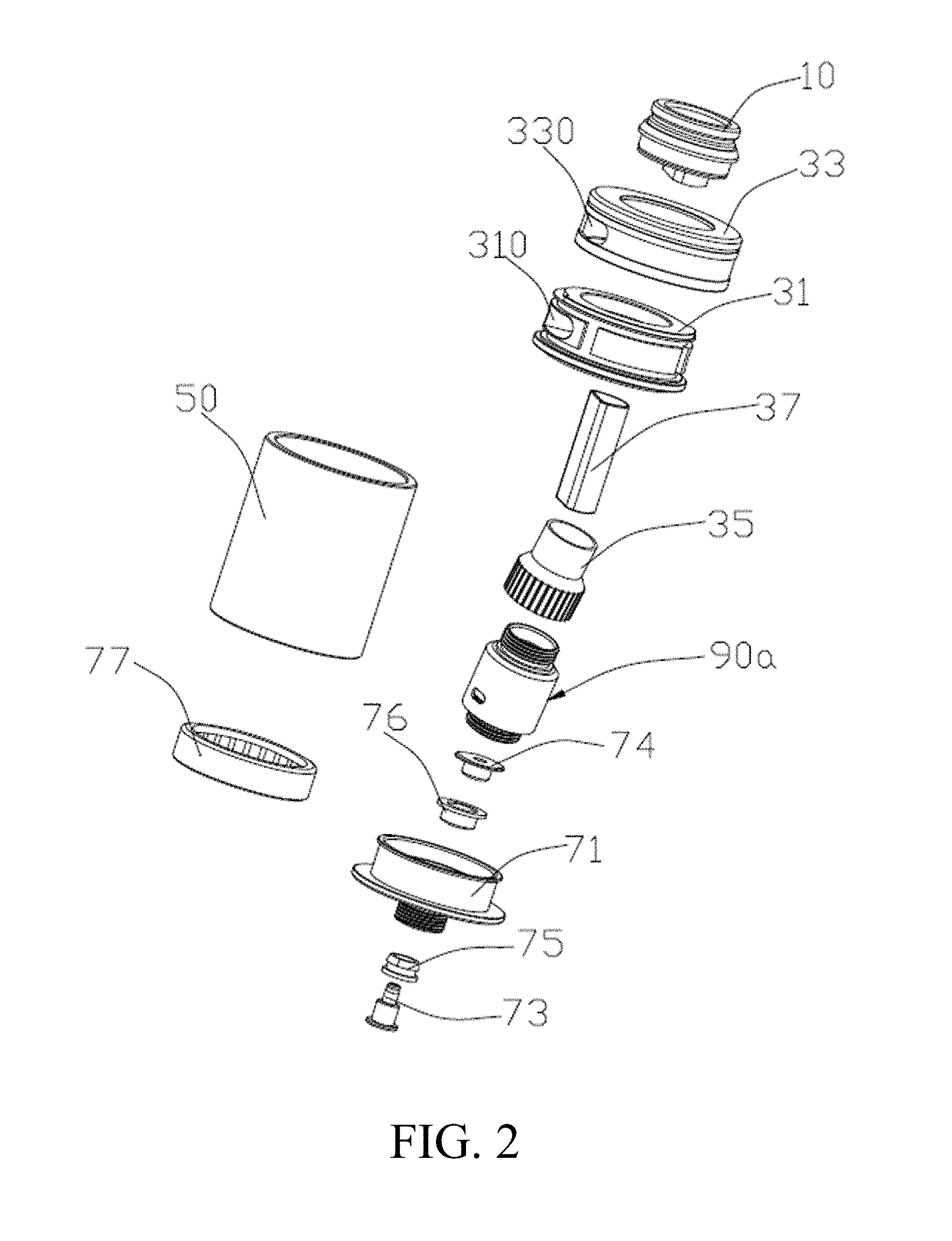
[0027] FIG. 2 is an exploded view of the atomizer shown in FIG. 1;
[0028] FIG. 3 is an exploded view of the atomizing head of the atomizer of FIG. 2;
[0029] FIG. 4 is a cross-sectional view of the atomizer of FIG. 2, which also shows the direction of the airflow;
[0030] FIG. 5 is an exploded view of the atomizing head of the second embodiment of the present disclosure;
[0031] FIG. 6 is a perspective view of the atomizing head of FIG. 5;
[0032] FIG. 7 is a cross-sectional view of the atomizing head of FIG. 5;
[0033] FIG. 8 is a cross-sectional view of the atomizing head of FIG. 5 in another direction;
[0034] FIG. 9 is a perspective view of an atomizing head of the third embodiment of the present disclosure;
[0035] FIG. 10 is an exploded view of the atomizing head shown in FIG. 9;
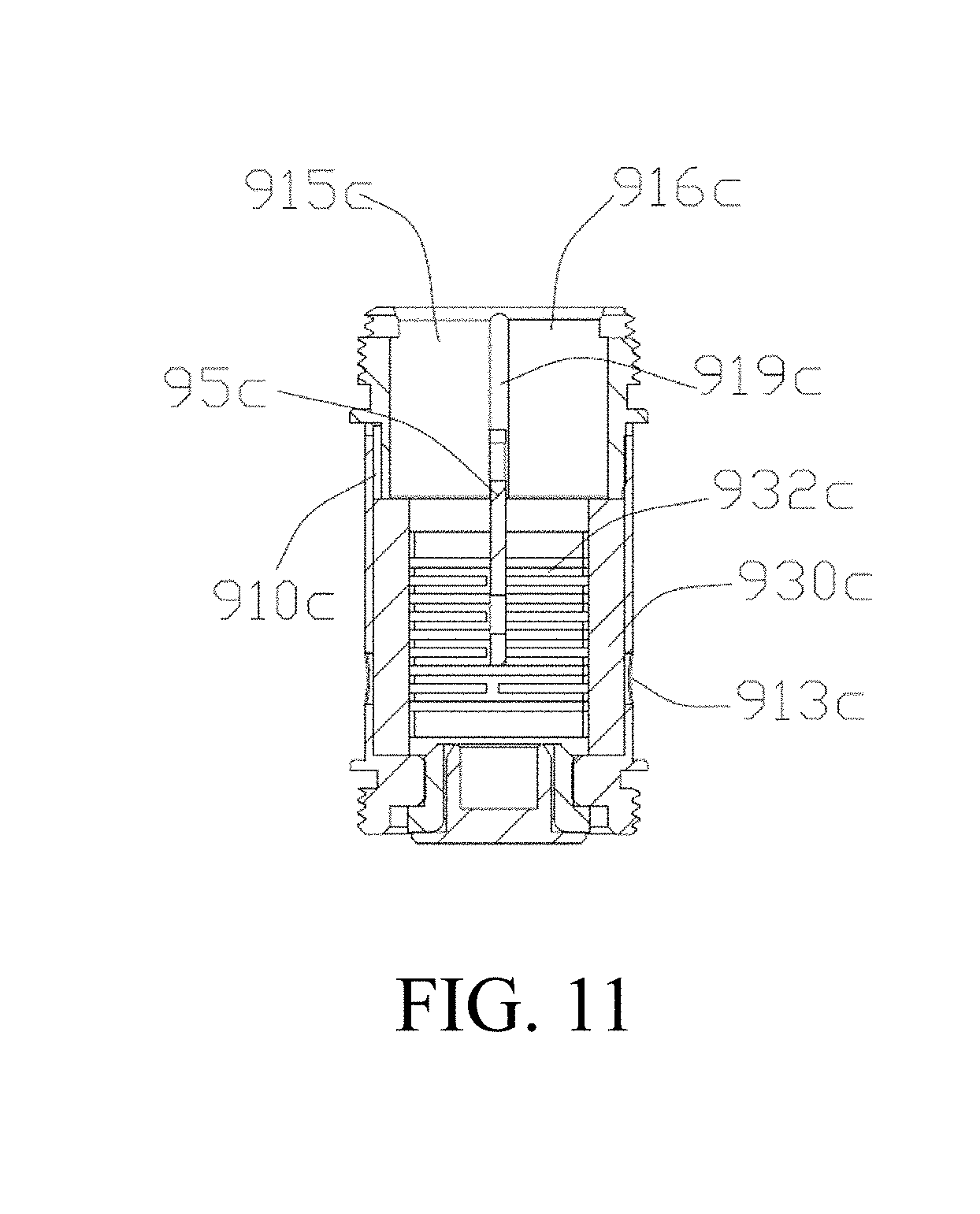
[0036] FIG. 11 is a cross-sectional view of the atomizing head of FIG. 9 taken along its axial direction.
[0037] The following table list various components and reference numerals thereof.
TABLE-US-00001 Atomizer 100 Mouthpiece connector 10 Inlet and outlet assembly 30 Air adjusting inner ring 31 Intake hole 310 Liquid injection port 312 Air adjusting outer ring 33 Adjustment groove 330 Vent pipe 35 Outlet pipe 37 Liquid storage tube 50 Reservoir chamber 51 Lower cover assembly 70 Lower cover 71 First through hole 710 First positive electrode contact 73 Second positive electrode First insulating ring 75 contact 74 Second insulating ring 76 Sealing ring 77 Atomizing head 90a/90b/90c Atomizing head sleeve 91a/91b/91c Atomizing chamber Base 911a/911b 910a/910b/910c Tube portion 912a/912b Liquid inlet hole 913a/913b/913c Vent 914a/914b/914c Air inlet 915a/915b/915c Air outlet 916a/916b/916c Intake passage 917 Outlet passage 918 Atomizing assembly 93a/93b/93c Liquid guiding member Receiving hole 9301 930a/930b/930c Heating element 932a/932b/932c Fixing seat 934 Liquid guiding groove 9341 Separator 95a/95b/95c latching groove 950a Atomizing head positive electrode contact 96 Atomizing head insulating ring 97 Top cover 911c Tube portion 912c receiving groove 919c Notch 920c
DETAILED DESCRIPTION OF PREFERRED EMBODIMENTS
[0038] It will be appreciated that for simplicity and clarity of illustration, where appropriate, reference numerals have been repeated among the different figures to indicate corresponding or analogous elements. In addition, numerous specific details are set forth in order to provide a thorough understanding of the embodiments described herein. However, it will be understood by those of ordinary skill in the art that the embodiments described herein can be practiced without these specific details. In other instances, methods, procedures and components have not been described in detail so as not to obscure the related relevant feature being described. Also, the description is not to be considered as limiting the scope of the embodiments described herein. The drawings are not necessarily to scale and the proportions of certain parts may be exaggerated to better illustrate details and features of the present disclosure.
[0039] Several definitions that apply throughout this disclosure will now be presented.
[0040] The term "coupled" is defined as connected, whether directly or indirectly through intervening components, and is not necessarily limited to physical connections. The connection can be such that the objects are permanently connected or releasably connected. The term "comprising," when utilized, means "including, but not necessarily limited to"; it specifically indicates open-ended inclusion or membership in the so-described combination, group, series and the like.
[0041] When a feature or element is herein referred to as being "on" another feature or element, it can be directly on the other feature or element or intervening features and/or elements may also be present.
[0042] Terminology used herein is for the purpose of describing particular embodiments only and is not intended to be limiting of the disclosure. As used herein, the term "and/or" includes any and all combinations of one or more of the associated listed items and may be abbreviated as "/".
[0043] Referring to FIG. 1 and FIG. 2, in an embodiment of the present disclosure, the atomizer 100 includes a mouthpiece connector 10, an inlet and outlet assembly 30, a liquid storage tube 50, a lower cover assembly 70, and an atomizing head (hereinafter referred to as 90a/90b/90c). The inlet and outlet assembly 30 is sleeved on the outer circumference of the mouthpiece connector 10 for adjusting the amount of outside air entering the atomization head. The liquid storage tube 50 is connected between the inlet and outlet assembly 30 and the lower cover assembly 70 for storing the liquid smoke. The atomizing head is received in the liquid storage tube 50 and in communication with the mouthpiece connector 10 for adsorbing the cigarette liquid stored in the liquid storage tube 50, and heating the cigarette liquid to generate smoke under electric driving. The smoke can flow out via the mouthpiece connector 10 for the user to inhale.
[0044] Specifically, the inlet and outlet assembly 30 includes a conditioned inner ring 31, a air adjusting outer ring 33, a vent pipe 35, and an air outlet pipe 37. The air adjusting inner ring 31 is sleeved on the mouthpiece connector 10, an intake hole 310 is defined in the air adjusting inner ring 31. The air adjusting outer ring 33 is rotatably sleeved on the air adjusting inner ring 31, an adjustment groove 330 in communication with or disengaging the intake hole 310 is formed in the peripheral wall. In use, the user can change the area of the intake air by rotating the air adjusting outer ring 33 to change the area of communication between the adjustment groove 330 and the intake hole 310.
[0045] Furthermore, the air adjusting inner ring 31 is further provided with a liquid injection port 312 (shown in FIG. 4) which is in communication with or is staggered from the adjustment groove 330. Rotating the air adjusting outer ring 33 to make the adjustment groove 330 in communication with the liquid injection port 312, thereby cigarette liquid can be injected into the liquid storage tube 50 via the liquid injection port 312, the operation is simple and convenient.
[0046] The vent pipe 35 has a substantially tubular body that is open at both ends. The vent pipe 35 is in communication between the air adjusting inner ring 31 and the atomizing head, and is for guiding outside air entering through the intake hole 310 into the atomizing head. The air outlet pipe 37 is a tubular pipe open at both ends, and is disposed in the vent pipe 35 and is in communication between the atomizing head and the mouthpiece connector. The air outlet pipe 37 is configured for guiding the smoke formed by the atomizing head under the electric driving to the mouthpiece connector 10.
[0047] The liquid storage tube 50 is a tubular tube open at both ends and is in liquid communication between the air adjusting inner ring 31 and the lower cover assembly 70. The liquid storage tube 50 together with the lower cover assembly 70 to define a reservoir chamber 51 for storing the liquid smoke (as shown in FIG. 4). The atomizing head is housed in the reservoir chamber 51 for adsorbing and atomizing the cigarette liquid received in the liquid storage tube 50 to generate smoke. The smoke is mixed with the outside air and then flows out of the mouthpiece connector 10 for the user to inhale.
[0048] Referring to FIG. 2 and FIG. 4 together, the lower cover assembly 70 includes a lower cover 71, a first positive electrode contact 73, a second positive electrode contact 74, a first insulating ring 75, and a second insulating ring 76.
[0049] The lower cover 71 is provided with a first through hole 710, the first positive electrode contact 73 extends through first through hole 710. In order not to damage the sealing effect of the lower cover 71, the first positive electrode contact 73 and the first through hole 710 are sealing connected together. The first positive electrode contact 73 and the first through hole 710 are interference fitted together or screwed together. The first insulating ring 75 is disposed between the first positive electrode contact 73 and the first through hole 710 to electrically isolate the first positive electrode contact 73 and the lower cover 71 while enhancing the sealing effect.
[0050] The second positive electrode contact 74 is sleeved in the second insulating ring 76. The second positive electrode contact 74 and the second insulating ring 76 are inserted into one end of the first through hole 710 away from the first positive electrode contact 73, so that the first positive electrode contact 73 can be inserted into and electrically contacts with the second positive electrode contact 74.
[0051] Furthermore, in order to enhance the sealing property of the reservoir chamber 51, a sealing ring 77 is disposed between the liquid storage tube 50 and the lower cover 71.
[0052] Referring to FIG. 3 and FIG. 4 together, in the first embodiment of the present disclosure, the atomizing head 90a includes an atomizing head sleeve 91a having an atomizing chamber 910a therein, an atomizing assembly 93a, and a separator 95a. The atomizing head sleeve 91a is generally a tubular body open at both ends and includes a base 911a and a tube portion 912a provided on the base 911a. A liquid inlet hole 913a in communication with the liquid storage tube 50 is defined on the pipe wall of the tube portion 912a, a vent 914a in communication with the atomizing chamber 910a is defined at the top of the tube portion 912a.
[0053] The atomizing assembly 93a is received in the atomizing chamber 910a. the atomizing assembly 93a includes a liquid guiding member 930a, a heating element 932a, and a fixing seat 934. The liquid guiding member 930a is provided with a receiving hole 9301. The heating element 932a is housed in the receiving hole 9301. The fixing base 934 is sleeved outside of the liquid guiding member 930a and is provided with a liquid guiding groove 9341 in communication with the liquid inlet hole 913a. In one embodiment, the receiving hole 9301 is perpendicular to the atomizing head sleeve 91a.
[0054] In one embodiment, the atomizing assembly 93a is received in the atomizing chamber 910a in a direction perpendicular to the axis of the atomizing head sleeve 91a. The liquid guiding member 930a is a substantially semi-cylindrical body. The receiving hole 9301 is disposed along the axial direction of the liquid guiding member 930a and extends through the opposite ends of the liquid guiding member 930a. The axial direction of the receiving hole 9301 is perpendicular to the axial direction of the atomizing head sleeve 91a. The heating element 932a is a hollow cylindrical spiral heating wire open at both ends and is housed in the receiving hole 9301 in the axial direction of the receiving hole 9301. It can be understood that, in other embodiments, the heating element 932a may also be a hollow heating pipe open at both ends. The fixing base 934 is a hollow semi-cylindrical shape engaging with the liquid guiding member 930a and is sleeved outside of the liquid guiding member 930a. The liquid guiding groove 9341 in communication with the liquid inlet hole 913a is respectively defined at both ends of the fixing seat 934 in the radial direction thereof.
[0055] The separator 95a is connected between the atomizing assembly 93a and the air outlet pipe 37, and isolates the vent 914a to form an air inlet 915a and an air outlet 916a on both sides of the atomizing assembly 93a. The separator 95a is perpendicular to the axis of the heating element 932a, whereby the air inlet 915a is in communication with the opening of one end of the heating element 932a, the air outlet 916a is in communication with the opening of the opposite end of the heating element 932a. The gap between the vent pipe 35 and the air outlet pipe 37 forms an intake passage 917 in communication with the intake hole 310 and the air inlet 915a. The air outlet pipe 37 defines an outlet passage 918 in communication with the air outlet 916a and the mouthpiece connector 10. Thereby, the outside air enters the intake passage 917 from the passage between the adjustment groove 330 and the intake hole 310, to the air inlet 915a, and to the inner cavity of the heating element 932a via the opening of one end of the heating element 932a. Then, the outside air is sufficiently mixed with the smoke, and sequentially flows out from the opposite end of the heating element 932a, the air outlet 916a, the outlet passage 918a, and the mouthpiece connector 10 for the user to inhale. Since the outside air flows through the entire inner cavity of the Heating element 932a, on the one hand, the outside air can take all the smoke out to prevent the smoke from being liquefied and formed into an effusion after the atomizer 100 is stopped. On the other hand, the temperature distribution of the inner cavity of the heating element 932a is uniform, without local overheating, and further, the leakage of the smoke liquid adsorbed by the liquid guiding member 930a due to the sudden drop in temperature and the sudden drop in pressure is prevented from forming effusions.
[0056] Specifically, the separator 95a has a substantial plate shape. An edge of the separator 95a facing one end of the atomizing assembly 93 is recessed inward to form a latching groove 950a engaging with the outer circumference of the fixing seat 934. In the embodiment, the latching groove 950a has a semi-circular arcuate shape. The separator 95a is engaged with the fixing seat 934 through the latching groove 950a in a direction perpendicular to the axis of the liquid guiding member 930a. In this embodiment, one end of the separator 95a is vertically clamped on the fixing seat 934 through the latching groove 950a. The vent 914a having a circular cross-section shape is isolated by the separator 95a to form an air inlet 915a and an air outlet 916a. The air inlet 915a and the air outlet 916a has a semicircular cross-section, respectively. The cross section of the air outlet pipe 37 is a semicircular shape matching the air outlet 916a, and one end of the separator 95a with respect to the fixing seat 934 abuts against the air outlet pipe 37. The air inlet 915a and the air outlet 916a are in communication with each other through the inner cavity of the heating element 932a, so that the outside airflow passes from the intake hole 310, the intake passage 917, and the air inlet 915a successively, to the inner cavity of the heating element 932a in the lateral direction, and then flowing out through the air outlet 916a, the outlet passage 918 and the mouthpiece connector 10 successively.
[0057] Furthermore, the atomizing head 90a further includes an atomizing head positive electrode contact 96 and an atomizing head insulating ring 97. The atomizing head positive electrode contact 96 is disposed at the bottom of the base 911a and electrically connected to the first positive electrode contact 73 through the second positive electrode contact 74. The atomizing head insulating ring 97 is disposed between the atomizing head positive electrode contact 96 and the base 911a and electrically insulates both.
[0058] Referring to FIG. 5 and FIG. 6, in the second embodiment of the present disclosure, the atomizing head 90b includes an atomizing head sleeve 91b having an atomizing chamber 910b (shown in FIG. 7) therein, an atomizing assembly 93b, and a separator 95. The atomizing head sleeve 91b is generally a tubular body open at both ends. The atomizing head sleeve 91b includes a base 911b and a tube portion 912b provided on the base 911b. The corresponding positions of the bottom edge of the tube portion 912b and the top edge of the base 911b are recessed to form an arc-shaped notch, and when the two are assembled integrally, the corresponding notches collectively define a liquid inlet hole 913b in communication with the liquid storage tube 50. A vent 914b in communication with the atomizing chamber 910b is defined at the top of the tube portion 912b.
[0059] The atomizing assembly 93b is received in the atomizing chamber 910, especially the atomizing assembly 93b is received in the atomizing chamber 910b in a direction perpendicular to the axial direction of the atomizing head sleeve 91b. The atomizing assembly 93b includes a liquid guiding member 930b and a heating element 932b. The liquid guiding member 930b has a cylindrical rod shape and is inserted into the liquid inlet hole 913b in the axial direction of the liquid inlet hole 913b. The heating element 932b is a hollow heat generating tube open at both ends, a liquid inlet groove is defined on the circumferential side of the heat generating tube. It can be understood that, in other embodiments, the heating element 932b can also be a hollow cylindrical spiral heating open at both ends. The heating element 932b is sleeved on the outer circumference of the liquid guiding member 930b along the axial direction of the liquid guiding member 930b.
[0060] Referring to FIG. 7 and FIG. 8, the separator 95b has a substantially long plate shape, which is disposed on the top of the atomizing assembly 93b in the direction parallel to the axis of the liquid guiding member 930b. In the embodiment, one end of the separator 95b abuts against the top of the heating element 932b in the axial direction of the liquid guiding member 930b, the opposite end of the separator 95b is clamped in the vent 914b and isolates the vent 914b to form the air inlet 915b and the air outlet 916b. The air inlet 915b and the air outlet 916b are in communication with each other through the bottom of the outer periphery of the heating element 932b. The external airflow passes from the air inlet 915b, to the bottom along the top of one side of the outer circumference of the heating element 932b, and to the top along the bottom of the other side of the outer periphery of the heating element 932b, then flows out through the air outlet 916b. Thus, the external airflow can flow through the entire heating element 932b in the atomizing chamber 910b, thereby reducing the temperature difference and avoiding effusion problems. Further, the outside air can bring all the smoke out, to prevent the smoke from returning to the liquid state and forming effusions after the atomizer 100 is stopped.
[0061] Referring to FIGS. 9-11, in the third embodiment of the present disclosure, the atomizing head 90c includes an atomizing head sleeve 91c having an atomizing chamber 910c therein, an atomizing assembly 93c, and a separator 95c. The atomizing head sleeve 91c is generally tubular open at two ends. The atomizing head sleeve 91c includes a top cover 911c and a tube portion 912c connected to the lower portion of the top cover 911c. The top cover 911c has a tubular shape open at two ends, the opposite sides of the inner wall surface are provided with a receiving groove 919c in the direction of the axis of the inner wall. A vent 914c is defined at the top of the top cover 911c. The top edge of the tube portion 912c and the corresponding position of the receiving groove 919c on the inner wall of the top cover 911c are recessed to form a notch 920c, when the receiving groove 919c and the notch 920c are integrally assembled, the receiving groove 919c is aligned with and in communication with the corresponding notch 920c.
[0062] The atomizing assembly 93c is housed in the atomizing chamber 910c in the axial direction parallel to the atomizing head sleeve 91c and includes a liquid guiding member 930c and a Heating element 932c. The liquid guiding member 930c has a hollow cylindrical rod shape open at two ends. A liquid inlet hole 913c in communication with the liquid guiding member 930c is defined on the circumferential side of the tube portion 912c. In the embodiment, the heating element 932c is a hollow cylindrical spiral heating wire that is open at two ends. The heating element 932c is axially sleeved in the liquid guiding member 930c along the liquid guiding member 930c and abuts against the inner wall of the liquid guiding member 930c. It can be understood that, in other embodiments, the heating element 932c can also be a hollow cylindrical tube with an opening at two ends.
[0063] The separator 95c is substantially a T-shaped plate. The wider end of the separator 95c is supported on the tube portion 912c, and is inserted into the notch 920c and the receiving groove 919c.
[0064] The narrower end of the separator 95c is inserted into the heating element parallelly along the axial direction of the liquid guiding member 930c, to isolate the vent 914c to form the air inlet 915c and the air outlet 916c. The air inlet 915c and the air outlet 916c communicate with each other through the bottom of the inner cavity of the heating element 932c. The external airflow flows in through the air inlet 915c, to the bottom along the top of the inner side of the heating element 932c, and to the top along the bottom of the other side of the heating element 932c and flows out through the air outlet 916c. Thus, the external airflow can pass through the entire heating element 932c in the atomizing chamber 910c, thereby reducing the temperature difference and solving the problem of fluid accumulation. On the other hand, the outside air can bring all the smoke out, to prevent the smoke from returning to the liquid state and forming effusions after the atomizer 100 is stopped.
[0065] The present disclosure also provides an electronic cigarette (not shown) having any one of the above atomizer 100.
[0066] In the present disclosure, the vents 914a/b/c of the atomizing heads 90a/b/c are separated by the separators 95a/b/c to form the air inlet 915a/b/c and the air outlet 916a/b/c. The air inlet 915a/b/c and the air outlet 916a/b/c are in communication with each other through the inside chamber, the inner bottom or the outer bottom of the heating elements 932a/b/c in the atomizing assemblies 93a/b/c. Thereby, when the outside air enters, the external airflow can across through or flow through the entire heating element 932a/b/c in the atomizing chamber 910c, thereby reducing the temperature difference and avoiding effusion problems. Further, the outside air can bring all the smoke out, to prevent the smoke from returning to the liquid state and forming effusions after the atomizer 100 is stopped.
[0067] The above-mentioned embodiments merely represent several implementations of the present application, and the descriptions thereof are more specific and detailed, but they shall not be understood as a limitation on the scope of the present application. It should be noted that, for those of ordinary skill in the art, variations and improvements may still be made without departing from the concept of the present application, and all of which shall fall into the protection scope of the present application. Therefore, the scope of protection of the present application shall be subject to the appended claims.
* * * * *
D00000
D00001
D00002
D00003
D00004
D00005
D00006
D00007
D00008
D00009
XML
uspto.report is an independent third-party trademark research tool that is not affiliated, endorsed, or sponsored by the United States Patent and Trademark Office (USPTO) or any other governmental organization. The information provided by uspto.report is based on publicly available data at the time of writing and is intended for informational purposes only.
While we strive to provide accurate and up-to-date information, we do not guarantee the accuracy, completeness, reliability, or suitability of the information displayed on this site. The use of this site is at your own risk. Any reliance you place on such information is therefore strictly at your own risk.
All official trademark data, including owner information, should be verified by visiting the official USPTO website at www.uspto.gov. This site is not intended to replace professional legal advice and should not be used as a substitute for consulting with a legal professional who is knowledgeable about trademark law.