Battery Powered Device
CHEN; Chia-Chang ; et al.
U.S. patent application number 15/925113 was filed with the patent office on 2019-04-25 for battery powered device. The applicant listed for this patent is STL Technology Co.,Ltd.. Invention is credited to Chia-Chang CHEN, Tao-Cheng WU.
| Application Number | 20190123579 15/925113 |
| Document ID | / |
| Family ID | 66169565 |
| Filed Date | 2019-04-25 |

| United States Patent Application | 20190123579 |
| Kind Code | A1 |
| CHEN; Chia-Chang ; et al. | April 25, 2019 |
BATTERY POWERED DEVICE
Abstract
The invention provides a battery powered device, which comprises a battery pack, at least one switch, a power management chip, and a pre-powered circuit. The pre-powered circuit comprises a buck and current-limiting module. The buck and current-limiting module comprises at least one zener diode and at least one current-limiting resistor. When the switch is turned off, the battery pack will be powered to a system device by the pre-powered circuit. Thus, the battery pack can be powered to the system device by the pre-powered circuit even if the battery powered device is operated in a standby mode. Besides, the power management chip can be operated in the standby state when the battery powered device is powered by the pre-powered circuit, so as to reduce the consumption of the battery energy and therefore extend the powered time of the battery powered device.
| Inventors: | CHEN; Chia-Chang; (Kaohsiung City, TW) ; WU; Tao-Cheng; (Kaohsiung City, TW) | ||||||||||
| Applicant: |
|
||||||||||
|---|---|---|---|---|---|---|---|---|---|---|---|
| Family ID: | 66169565 | ||||||||||
| Appl. No.: | 15/925113 | ||||||||||
| Filed: | March 19, 2018 |
| Current U.S. Class: | 1/1 |
| Current CPC Class: | H02J 2207/20 20200101; H02J 7/00306 20200101; H02J 7/0068 20130101; H02J 9/061 20130101; H02M 3/158 20130101; H02J 7/0029 20130101; H02M 2001/327 20130101; H02M 3/156 20130101 |
| International Class: | H02J 9/06 20060101 H02J009/06; H02J 7/00 20060101 H02J007/00 |
Foreign Application Data
| Date | Code | Application Number |
|---|---|---|
| Oct 19, 2017 | CN | 201710974637.4 |
Claims
1. A battery powered device, which is used for providing a power to a system device, the battery powered device comprising: a battery pack consisted of a plurality of batteries; at least one switch connected between the battery powered device and the system device; a power management chip, connected to the switch, used for controlling the turning on or the turning off of the switch; and a pre-powered circuit connected between the battery pack and the system device, wherein the pre-powered circuit comprises a buck and current-limiting module, the buck and current-limiting module comprises at least one zener diode and at least one current limiting resistor, the zener diode is connected to the current-limiting resistor in a series, the battery pack is powered to the system device by the pre-powered circuit when the switch is turned off.
2. The battery powered device according to claim 1, wherein the switch is turned off by the controlling of the power management chip before an operation mode of the power management chip is to be transferred from a normal operation mode to a standby operation mode.
3. The battery powered device according to claim 1, wherein the pre-powered circuit further comprises a temperature protection module, the temperature protection module is connected to the buck and current-limiting module, and used for sensing an operation temperature of the buck and current-limiting module, a current loop between the battery pack, the pre-powered circuit, and the system device will be disconnected by the temperature protection module when the operation temperature of the buck and current-limiting module exceeds a temperature threshold.
4. The battery powered device according to claim 3, wherein the temperature protection module is an impedance element of positive temperature coefficient.
5. The battery powered device according to claim 3, wherein the temperature protection module is a thermistor, a polysilicon fuse, or a circuit breaker.
6. The battery powered device according to claim 1, wherein when the power management chip is operated in a normal operation mode, the switch will be turned on by the controlling of the power management chip, the battery pack is powered to the system device by the switch.
7. The battery powered device according to claim 2, wherein the power management chip receives a waking signal, the operation mode of the power management chip is transferred from the standby operation mode to the normal operation mode according to the waking signal.
8. The battery powered device according to claim 1, wherein the switch is a JFET, a MOSFET, a BJT, or a Relay.
Description
[0001] This non-provisional application claims priority claim under 35 U.S.C. .sctn. 119 (a) on China Patent Application No. 201710974637.4 filed Oct. 19, 2017, the entire contents of which are incorporated herein by reference.
FIELD OF THE INVENTION
[0002] The present invention relates to a battery powered device, particularly to a battery powered device capable of providing a standby power.
BACKGROUND
[0003] In order to avoid the power outage occurred during the system device performing the important task, the system device is able to be connected to an external battery powered device. When the power outage occurs, the required standby power that the system device performs the important task can be provided by the discharging of the system device.
[0004] In the past, the battery powered device is provided with a DC power converter (such as switched power converter or linear power converter) in the inside thereof. The battery powered device can buck the voltage of battery to the required working voltage of the system device by the DC power converter so as to power to the system device.
[0005] In general, the DC power converter is having the high cost of components that will increase the hardware cost of the battery powered device, and is having the higher power consumption that will easily cause the loss of battery energy, and is easy over-discharging during the discharging process, resulting in the damage of battery cell. Besides, a power management chip must be waked up when the battery powered device is powered via the DC power converter, so that the operation of the DC power converter can be controlled by the power management chip. However, the power management chip in a normal operation state is easy to cause that the battery energy of the battery powered device is exhausted quickly.
SUMMARY
[0006] It is one objective of the present invention to provide a battery powered device, which comprises a battery pack, at least one switch, a power management chip, and a pre-powered circuit. The battery pack can be powered to a system device via the pre-powered circuit even if the battery powered device is operated in a power-saving standby mode. Besides, the power management chip can be operated in a standby state when the battery powered device is powered to the system device via the pre-powered circuit, so as to reduce the consumption of the battery energy and therefore extend the powered time of the battery powered device.
[0007] It is another objective of the present invention to provide a battery powered device, in which the pre-powered circuit comprises a buck and current-limiting module. The buck and current-limiting module comprises at least one zener diode and at least one current limiting resistor. The discharging energy of the battery pack can be powered to the system device via the zener diode and the current limiting resistor. Thus, a minimum discharge voltage of the battery pack is limited by a voltage drop of the zener diode, a discharging current is limited by the current limiting resistor, thereby the thing that the battery pack is over-discharging and therefore damaged can be avoided.
[0008] It is another objective of the present invention to provide a battery powered device, wherein the pre-powered circuit further comprises a temperature protection module. When an operation temperature of the buck and current-limiting module exceeds a temperature threshold, the temperature protection module will generate a high impedance, so that a current loop between the battery pack, the pre-powered circuit, and the system device will be disconnected by the high impedance of the temperature protection module, in such a way that the buck and current-limiting module can avoid to be powered to the system device when over-heating, thereby the safety on the powered can be ensured.
[0009] To achieve the above objective, the present invention provides a battery powered device, which is used for providing a power to a system device, the battery powered device comprising: a battery pack consisted of a plurality of batteries; at least one switch connected between the battery powered device and the system device; a power management chip, connected to the switch, used for controlling the turning on or the turning off of the switch; and a pre-powered circuit connected between the battery pack and the system device, wherein the pre-powered circuit comprises a buck and current-limiting module, the buck and current-limiting module comprises at least one zener diode and at least one current limiting resistor, the zener diode is connected to the current-limiting resistor in a series, the battery pack is powered to the system device by the pre-powered circuit when the switch is turned off.
[0010] In one embodiment of the present invention, the switch is turned off by the controlling of the power management chip before an operation mode of the power management chip is to be transferred from a normal operation mode to a standby operation mode.
[0011] In one embodiment of the present invention, the pre-powered circuit further comprises a temperature protection module, the temperature protection module is connected to the buck and current-limiting module, and used for sensing an operation temperature of the buck and current-limiting module, a current loop between the battery pack, the pre-powered circuit, and the system device will be disconnected by the temperature protection module when the operation temperature of the buck and current-limiting module exceeds a temperature threshold.
[0012] In one embodiment of the present invention, the temperature protection module is an impedance element of positive temperature coefficient.
[0013] In one embodiment of the present invention, the temperature protection module is a thermistor, a polysilicon fuse, or a circuit breaker.
[0014] In one embodiment of the present invention, when the power management chip is operated in a normal operation mode, the switch will be turned on by the controlling of the power management chip, the battery pack is powered to the system device by the switch.
[0015] In one embodiment of the present invention, the power management chip receives a waking signal, the operation mode of the power management chip is transferred from the standby operation mode to the normal operation mode according to the waking signal.
[0016] In one embodiment of the present invention, the switch is a JFET, a MOSFET, a BJT, or a Relay.
BRIEF DESCRIPTION OF THE DRAWINGS
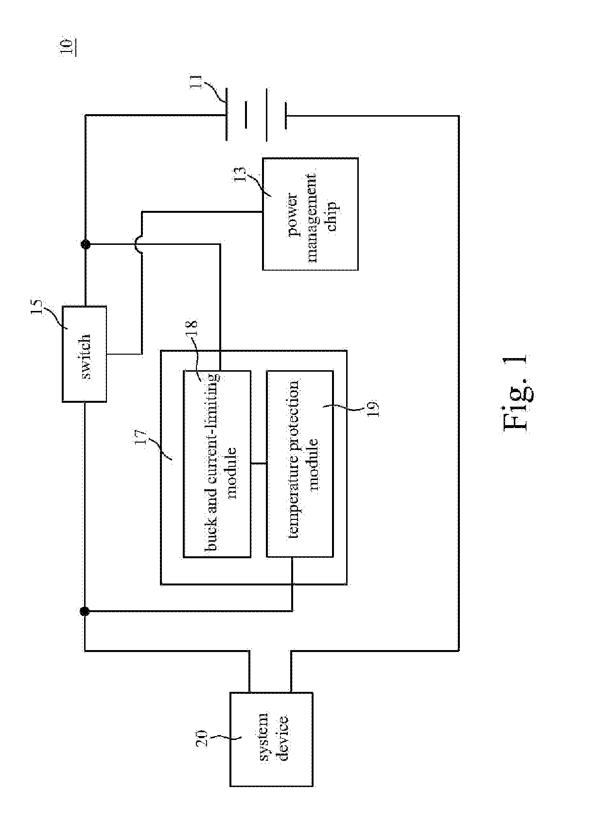
[0017] FIG. 1 is shown a circuit diagram of a battery powered device according to one embodiment of the present invention.
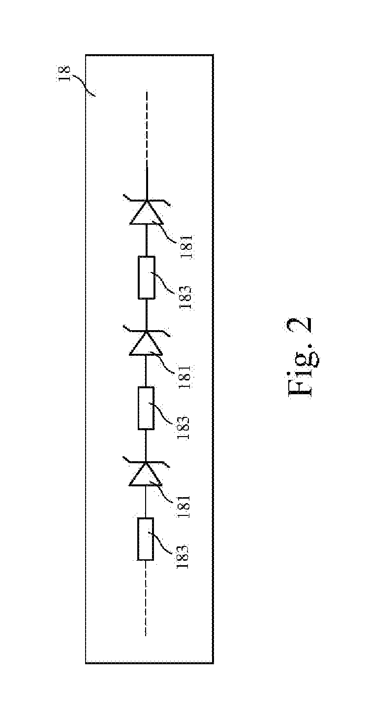
[0018] FIG. 2 is shown a circuit construction diagram of a buck and current-limiting module of a pre-powered circuit according to the present invention.
DETAILED DESCRIPTION OF THE PREFERRED EMBODIMENTS
[0019] Referring to FIG. 1, there is shown a circuit diagram of a battery powered device according to one embodiment of the present invention. As shown in FIG. 1, the battery powered device 10 of the present invention is connected to a system device 20, and used to be powered to the system device 20. The battery powered device 10 comprises a battery pack 11, a power management chip 13, at least one switch 15, and a pre-powered circuit 17. The battery pack 11 is consisted of a plurality of batteries in serial. The switch 15 is connected between the battery pack 11 and the system device 20. The switch 15 can be a JFET (Junction Field Effect Transistor), a MOSFET (Metal Oxide Semiconductor Field Effect Transistor), a BJT (Bipolar junction Transistor), or a Relay. The pre-powered circuit 17 is connected between the battery pack 11 and the system device 20, and it is a bypass powered circuit.
[0020] The power management chip 13 is connected to the switch 15, used for controlling the turning on or the turning off of the switch 15. When the power management chip 13 is operated in a normal operation mode, it will issue an enable signal to the switch 15, so that the switch 15 is turned on according to the enable signal, and a discharging energy of the battery pack 11 is powered to the system device 20 via the switch 15 turned on. In the contrary, before the operation mode of the power management chip is to be transferred from a normal operation mode to a standby operation mode, the power management chip 13 will issue a disable signal to switch 15 so that the switch 15 is turned off according to the disable signal. Afterwards, when the switch 11 is turned off and the power management chip 13 is operated in the standby operation mode, the discharging energy of the battery pack 11 will be powered to the system device 20 via the pre-powered circuit 17. Accordingly, a normal powered loop is formed between the battery pack 11, the switch 15, and the system device 20, and a bypass powered loop is formed between the battery pack 11, the pre-powered circuit 17, and the system device 20.
[0021] As shown in FIGS. 1 and 2, the pre-powered circuit 17 comprises a buck and current-limiting module 18. The buck and current-limiting module 18 comprises at least one zener diode 181 and at least one current limiting resistor 183. The zener diode 181 and the current limiting resistor 183 are connected together in a series. When the power management chip 13 is operated in the standby operation mode, the zener diode 181 can buck the battery voltage of the battery pack 11 to the required operating voltage of the system device 20, and the current limiting resistor 183 can limit the discharging current of the battery pack 11 within a current range allowed by the system device 20. Thus, the discharging energy of the battery pack 11 is powered to the system device 20 via the buck and current-limiting module 18. Besides, a minimum discharge voltage of the battery pack 11 is limited by a voltage drop of the zener diode 181, a discharging current of the battery pack 11 is limited by the current limiting resistor 183, thereby the thing that the battery pack 11 is over-discharging and therefore damaged can be avoided. In the present invention, the number of dispositions of the zener diodes 181 can be decided according to the required operation voltage of the system device 20, and the number of dispositions of the current limiting resistors 183 can be decided according to the current range allowed by the system device 20.
[0022] Accordingly, the battery pack 11 can still be powered to the system device 20 via the pre-powered circuit 17 when the battery powered device 10 of the present invention is operated in the power-saving standby mode, while the power management chip 13 operated in the standby state will reduce the consumption of battery energy of battery pack 11 so as to extend the powered time of the battery powered device 10.
[0023] Sequentially, the power management chip 13 is able to receive a waking signal, which is issued by the system device 20 or an external control device. When the power management chip 13 receives the waking signal, the operation mode of the power management chip 13 is able to be transferred from the standby operation mode to the normal operation mode according to the waking signal, and then the power management chip 13 sends an enable signal to the switch 15 so that the switch 15 can be again turned on by the enable signal.
[0024] The pre-powered circuit 17 further comprises a temperature protection module 19. The buck and current-limiting module 18 is connected to the system device 20 via the temperature protection module 19. In one embodiment of the present invention, the temperature protection module 19 is an impedance element of positive temperature coefficient, for example, thermistor, polysilicon fuse, or circuit breaker. An impedance value of the temperature protection module 19 will increase following to the temperature. The temperature protection module 19 is used for sensing an operation temperature of the buck and current-limiting module 18. When the operation temperature of the buck and current-limiting module 18 exceeds a temperature threshold, the temperature protection module 19 will generate a high impedance, so that the current loop between the battery pack, the pre-powered circuit, and the system device will be disconnected by the high impedance of the temperature protection module 19. By the configuration of the temperature protection module 19, the buck and current-limiting module 18 can avoid to be powered to the system device 20 when over-heating, thereby the safety on the powered can be ensured.
[0025] The above disclosure is only the preferred embodiment of the present invention, and not used for limiting the scope of the present invention. All equivalent variations and modifications on the basis of shapes, structures, features and spirits described in the claims of the present invention should be included in the claims of the present invention.
* * * * *
D00000
D00001
D00002
XML
uspto.report is an independent third-party trademark research tool that is not affiliated, endorsed, or sponsored by the United States Patent and Trademark Office (USPTO) or any other governmental organization. The information provided by uspto.report is based on publicly available data at the time of writing and is intended for informational purposes only.
While we strive to provide accurate and up-to-date information, we do not guarantee the accuracy, completeness, reliability, or suitability of the information displayed on this site. The use of this site is at your own risk. Any reliance you place on such information is therefore strictly at your own risk.
All official trademark data, including owner information, should be verified by visiting the official USPTO website at www.uspto.gov. This site is not intended to replace professional legal advice and should not be used as a substitute for consulting with a legal professional who is knowledgeable about trademark law.