Hybrid Electrochemical Cell
El-Kady; Maher F. ; et al.
U.S. patent application number 16/223869 was filed with the patent office on 2019-04-25 for hybrid electrochemical cell. The applicant listed for this patent is The Regents of the University of California. Invention is credited to Maher F. El-Kady, Richard B. Kaner.
| Application Number | 20190123409 16/223869 |
| Document ID | / |
| Family ID | 54936051 |
| Filed Date | 2019-04-25 |


View All Diagrams
| United States Patent Application | 20190123409 |
| Kind Code | A1 |
| El-Kady; Maher F. ; et al. | April 25, 2019 |
HYBRID ELECTROCHEMICAL CELL
Abstract
Disclosed is a hybrid electrochemical cell with a first conductor having at least one portion that is both a first capacitor electrode and a first battery electrode. The hybrid electrochemical cell further includes a second conductor having at least one portion that is a second capacitor electrode and at least one other portion that is a second battery electrode. An electrolyte is in contact with both the first conductor and the second conductor. In some embodiments, the hybrid electrochemical cell further includes a separator between the first conductor and the second conductor to prevent physical contact between the first conductor and the second conductor, while facilitating ion transport between the first conductor and the second conductor.
| Inventors: | El-Kady; Maher F.; (Los Angeles, CA) ; Kaner; Richard B.; (Pacific Palisades, CA) | ||||||||||
| Applicant: |
|
||||||||||
|---|---|---|---|---|---|---|---|---|---|---|---|
| Family ID: | 54936051 | ||||||||||
| Appl. No.: | 16/223869 | ||||||||||
| Filed: | December 18, 2018 |
Related U.S. Patent Documents
| Application Number | Filing Date | Patent Number | ||
|---|---|---|---|---|
| 15319286 | Dec 15, 2016 | 10211495 | ||
| PCT/US15/36082 | Jun 16, 2015 | |||
| 16223869 | ||||
| 62012835 | Jun 16, 2014 | |||
| Current U.S. Class: | 1/1 |
| Current CPC Class: | H01G 11/08 20130101; H01M 4/13 20130101; H01M 14/00 20130101; H01G 11/26 20130101; H01G 11/86 20130101; H01M 10/30 20130101; H01G 11/02 20130101; H01M 4/587 20130101; H01G 11/30 20130101; H01M 10/345 20130101; H01M 10/0525 20130101; H01M 4/386 20130101; H01M 4/505 20130101; H01M 4/525 20130101; H01M 10/052 20130101; Y02E 60/13 20130101; H01G 11/52 20130101; H01G 11/06 20130101; H01G 11/32 20130101; H01M 12/00 20130101; H01M 4/5825 20130101; H01G 11/04 20130101; H01G 11/46 20130101; H01M 4/485 20130101; H01G 11/50 20130101 |
| International Class: | H01M 14/00 20060101 H01M014/00; H01M 10/0525 20060101 H01M010/0525; H01M 4/13 20060101 H01M004/13; H01G 11/02 20060101 H01G011/02; H01G 11/08 20060101 H01G011/08; H01G 11/46 20060101 H01G011/46; H01G 11/52 20060101 H01G011/52; H01G 11/86 20060101 H01G011/86; H01M 10/34 20060101 H01M010/34; H01M 10/30 20060101 H01M010/30; H01M 10/052 20060101 H01M010/052; H01M 4/587 20060101 H01M004/587; H01M 4/58 20060101 H01M004/58; H01M 4/525 20060101 H01M004/525; H01M 4/505 20060101 H01M004/505; H01M 4/485 20060101 H01M004/485; H01M 4/38 20060101 H01M004/38; H01G 11/50 20060101 H01G011/50; H01G 11/32 20060101 H01G011/32; H01G 11/26 20060101 H01G011/26; H01G 11/06 20060101 H01G011/06; H01M 12/00 20060101 H01M012/00 |
Claims
1. A method of producing a hybrid electrochemical cell comprising: (a) fabricating a first conductor having a single portion that is both a first capacitor electrode and a first battery electrode; (b) fabricating a second conductor having at least one portion that is a second capacitor electrode and at least one other portion that is a second battery electrode; and (c) adding an electrolyte to both the first conductor and the second conductor.
2. The method of claim 1, wherein fabricating the second conductor comprises: (a) receiving a substrate having a carbon-based oxide film; and (b) generating a light beam that reduces portions of the carbon-based oxide film to a plurality of expanded and interconnected carbon layers that are electrically conductive, thereby forming an interconnected corrugated carbon-based network.
3. The method of claim 1, further comprising inserting a separator between the first conductor and the second conductor.
4. The method of claim 1, further comprising doping the first conductor with lithium ions.
5. The method of claim 1, wherein the hybrid electrochemical cell comprises lithium-ion (Li-Ion) material or chemistry.
6. The method of claim 1, wherein the hybrid electrochemical cell comprises a nickel-cadmium (Ni--Cd) chemistry, a nickel-metal hydride (Ni-MH) chemistry, or both.
7. The method of claim 6, wherein the first conductor comprises nickel oxyhydroxide (NiOOH), graphite, or both.
8. The method of claim 1, wherein the first battery electrode comprises hard carbon, silicon alloy, a composite alloy, or any combination thereof.
9. The method of claim 1, wherein the second capacitor electrode comprises an electric double layer capacitor.
10. The method of claim 1, wherein the second capacitor electrode is redox active and stores charge via intercalation pseudo-capacitance.
11. The method of claim 1, wherein the second capacitor electrode comprises a layered metal oxide, activated carbon, an interconnected corrugated carbon-based network, niobium pentoxide, or any combination thereof.
12. The method of claim 11, wherein the interconnected corrugated carbon-based network comprises a plurality of expanded and interconnected carbon layers.
13. The method of claim 12, wherein the plurality of expanded and interconnected carbon layers comprises at least one corrugated carbon sheet.
14. The method of claim 13, wherein each of the at least one corrugated carbon sheet has a thickness of 1 atom.
15. The method of claim 12, wherein each of the plurality of expanded and interconnected carbon layers has a thickness of about 5 .mu.m to 100 .mu.m.
16. The method of claim 1, wherein the second battery electrode comprises activated carbon, lithium cobalt oxide, lithium manganese oxide, lithium nickel oxide, lithium nickel manganese cobalt oxide, lithium nickel cobalt aluminum oxide, lithium titanium oxide, lithium iron phosphate, or any combination thereof.
17. The method of claim 1, wherein a ratio between the at least one portion that is the second capacitor electrode and the at least one other portion that is the second battery electrode is about 1:10 to about 10:1.
18. The method of claim 1, wherein the hybrid electrochemical cell has an energy density of about 20 watt-hour/kilogram (Wh/kg) to about 200 Wh/kg.
19. The method of claim 1, wherein the hybrid electrochemical cell has a power density of about 103 watt/kilogram (W/kg) to about 104 W/kg.
20. The method of claim 1, wherein the first conductor and the second conductor are interdigitated.
Description
PRIORITY
[0001] This application is a divisional of U.S. patent application Ser. No. 15/319,286, filed Dec. 15, 2016, which is a 35 USC 371 National Phase filing of International application no. PCT/US15/36082, filed Jun. 16, 2015, which claims the benefit of U.S. provisional patent application No. 62/012,835, filed Jun. 16, 2014, the disclosures of which are incorporated herein by reference in their entireties.
GOVERNMENT SUPPORT
[0002] This research was supported in part by the Ministry of Higher Education of Egypt through a graduate research fellowship--the Missions Program.
FIELD OF THE DISCLOSURE
[0003] The disclosure relates to electrochemical cells and in particular to a hybrid electrochemical cell having an energy density typical of a battery and a power density typical of a supercapacitor.
BACKGROUND
[0004] Batteries are used to power portable electronics such as smartphones, tablets, and laptop computers. Batteries have affected various aspects of modern living. There are numerous applications for batteries. Moreover, batteries are integral for renewable energy production from sun and wind as well as the development of electric and hybrid electric vehicles. Batteries store a large amount of charge through electrochemical reactions and typically take hours to recharge. What is needed is a hybrid electro-chemical cell that is quickly rechargeable like a supercapacitor and that stores a large amount of charge like a battery.
SUMMARY
[0005] A hybrid electrochemical cell having a first conductor with at least one portion that is both a first capacitor electrode and a first battery electrode is disclosed. The hybrid electrochemical cell further includes a second conductor having at least one portion that is a second capacitor electrode and at least one other portion that is a second battery electrode. An electrolyte is in contact with both the first conductor and the second conductor.
[0006] In some embodiments, the hybrid electrochemical cell further includes a separator between the first conductor and the second conductor to prevent physical contact between the first conductor and the second conductor, while facilitating ion transport between the first conductor and the second conductor. Moreover, at least one exemplary embodiment of the hybrid electrochemical cell relies on lithium-ion (Li-Ion) chemistry. Other exemplary embodiments of the hybrid electrochemical cell are based upon nickel-cadmium (Ni--Cd) and nickel-metal hydride (Ni-MH) chemistries. Further still, some embodiments of the hybrid electrochemical cell are sized to power electric vehicles for transportation, while other embodiments are sized small enough to power implantable medical devices.
[0007] Generally described herein, in certain embodiments, is an energy storage technology comprising a supercapacitor designed to store charge on the surface of large surface area materials. In some applications, the disclosed supercapacitor captures and releases energy in seconds and can do so through millions of cycles. Further described herein is an improvement that provides greater charge storage capacity using, for example, power systems that combine supercapacitors and batteries that provide for a high charge storage capacity of batteries and the quick recharge of supercapacitors. Indeed, the inventors have identified, and have described methods, devices, and systems that solve several long-felt and unmet needs for devices that include electrochemical energy storage having relatively fast energy recharge times in contrast to batteries with relatively slow recharge times that limit mobility of a user.
[0008] In certain aspects, described herein are power systems, methods, and devices based upon combinations of supercapacitors and batteries for various applications, including by way of non-limiting examples electric and hybrid electric vehicles. For example, electric vehicles are often powered by one of the following energy storage systems: fuel cells, batteries, or supercapacitors. However, installing only one type of conventional energy storage is often insufficient.
[0009] In addition, the running cost of the normally available supercapacitor and battery-based power systems is expensive and they are relatively bulky in size. As a result, such power systems are not usable in a practical manner with portable electronics, such as smartphones, tablets, and implantable medical devices.
[0010] Advantages of the subject matter described herein are robust and numerous. For example, one advantage of the subject matter described herein is a hybrid electrochemical cell that provides the high energy density of a battery with the high power density of a supercapacitor. In some embodiments, the hybrid electrochemical cells provided herein do not require an electronic converter and/or bulky packaging. As another example, the subject matter described herein provides a hybrid electrochemical cell that combines a supercapacitor and battery that does not necessarily require wiring a battery to a supercapacitor in parallel, nor does it necessarily require expensive electronic converters that are required to control power flow between the battery and supercapacitor.
[0011] In one aspect, described herein are methods, devices, and systems that provide for a hybrid electrochemical cell with a first conductor having a single portion that is both a first capacitor electrode and a first battery electrode. For example, the hybrid electrochemical cell further includes a second conductor having at least one portion that is a second capacitor electrode and at least one other portion that is a second battery electrode. In certain applications, an electrolyte is in contact with both the first conductor and the second conductor.
[0012] In some embodiments, the hybrid electrochemical cell further includes a separator between the first conductor and the second conductor to prevent physical contact between the first conductor and the second conductor, while still facilitating ion transport between the first conductor and the second conductor. Moreover, at least one exemplary embodiment of the hybrid electrochemical cell relies on lithium-ion (Li-Ion) chemistry. Other exemplary embodiments of the hybrid electrochemical cell are based upon nickel-cadmium (Ni--Cd) and/or nickel-metal hydride (Ni-MH) chemistries. Further still, some embodiments of the hybrid electrochemical cell are sized to power electric vehicles for transportation, while other embodiments are sized small enough to power implantable medical devices.
[0013] In one aspect, provided herein are methods, devices, and systems comprising a hybrid electrochemical cell comprising: (a) a first conductor having at least a one portion that is both a first capacitor electrode and a first battery electrode; (b) a second conductor having at least one portion that is a second capacitor electrode and at least one other portion that is a second battery electrode; and (c) an electrolyte in contact with both the first conductor and the second conductor. In some embodiments, provided herein is a method, device, and system that comprises a hybrid electrochemical cell that contains a separator between the first conductor and the second conductor that is configured in a manner to prevent or reduce physical contact between the first conductor and the second conductor and that facilitates ion transport between the first conductor and the second conductor. In some embodiments, the hybrid electrochemical cell comprises lithium-ion (Li-Ion) chemistry. In further or additional embodiments, the first conductor of the hybrid electrochemical cell is negative and is doped with lithium ions. In certain embodiments, the hybrid electrochemical cell comprises a first conductor that comprises a graphite negative electrode. In some embodiments, a first negative battery electrode comprises: hard carbon, silicon alloy, and/or composite alloy. In certain embodiments, the second battery electrode comprises a layered metal oxide positive electrode, and the second capacitor electrode comprises an activated carbon positive electrode. In some embodiments, provided is a hybrid electrochemical cell wherein the second positive battery electrode comprises: lithium cobalt oxide, lithium manganese oxide, lithium nickel oxide, lithium nickel manganese cobalt oxide, lithium nickel cobalt aluminum oxide, lithium titanium oxide, or lithium iron phosphate. In certain applications, the second capacitor electrode and the second battery electrode are delineated. In some embodiments, the second capacitor electrode and the second battery electrode are connected internally in parallel on one cell, and wherein the capacitor electrode acts as a buffer to prevent or reduce high rate charge and discharge of the battery. In some embodiments, the ratio between the portion of the second capacitor electrode and the second battery electrode is about 1:1. In some applications, the ratio between the portion of the second capacitor electrode and the second battery electrode is within the range of from about 1:10 to about 10:1. In still further or additional embodiments, a desirable power density of the hybrid electrochemical cell is achieved with an increase of a ratio between the portion of the second capacitor electrode and the second battery electrode. In yet further or additional embodiments, an energy density of the hybrid electrochemical cell is achieved with a decrease of the ratio between the portion of the second capacitor electrode and the second battery electrode. In still further or additional embodiments, the second capacitor electrode comprises an electric double layer capacitor (EDLC) in which charge is stored in the double layers. In some of these additional embodiments, the second capacitor electrode comprises activated carbon.
[0014] In another aspect, described herein are methods, devices, and systems that provide for a hybrid electrochemical cell comprising: (a) a first conductor having at least a one portion that is both a first capacitor electrode and a first battery electrode; (b) a second conductor having at least one portion that is a second capacitor electrode and at least one other portion that is a second battery electrode; and (c) an electrolyte in contact with both the first conductor and the second conductor, provided that at least one second capacitor electrode comprises an electric double layer capacitor (EDLC) in which charge is stored in the double layers. In some of these additional embodiments, the second capacitor electrode comprises an interconnected corrugated carbon-based network (ICCN). In certain embodiments, the interconnected corrugated carbon-based network (ICCN) electrode comprises a plurality of expanded and interconnected carbon layers that include a corrugated carbon layer. In some embodiments, each expanded and/or interconnected carbon layer comprises at least one corrugated carbon sheet that is about one atom thick. In some embodiments, each expanded and interconnected carbon layer comprises a plurality of corrugated carbon sheets. In further or additional embodiments, the thickness of the ICCN, as measured from cross-sectional scanning electron microscopy (SEM) and profilometry, is around about 7 or about 8 .mu.m. In some embodiments, a range of thicknesses of the plurality of expanded and interconnected carbon layers making up the ICCN is from around about 5 .mu.m to 100 .mu.m. In further or additional embodiments, the second capacitor electrode is redox active to store charge via intercalation pseudo-capacitance. In some of these embodiments, the second capacitor electrode comprises niobium pentoxide (Nb.sub.2O.sub.5).
[0015] In another aspect, described herein are methods, devices, and systems comprising a hybrid electrochemical cell comprising: (a) a first conductor having at least a one portion that is both a first capacitor electrode and a first battery electrode; (b) a second conductor having at least one portion that is a second capacitor electrode and at least one other portion that is a second battery electrode; and (c) an electrolyte in contact with both the first conductor and the second conductor, provided that the hybrid electrochemical cell is integrated on a micro-scale. In certain applications, the micro-hybrid electrochemical cell is flexible in size and shape. In some embodiments, the micro-hybrid electrochemical cell is integrated into an implantable medical device, a smart card, a radio frequency identification (RFID) tag, a wireless sensor, or a wearable electronic. In further or additional embodiments, the micro-hybrid electrochemical cell is incorporated into a self-powered system. In some applications, the micro-hybrid electrochemical cell is fabricated on the backside of a solar cell of a device. In some embodiments, the second capacitor electrode and the second battery electrode each has an electrode digit with a length L, a width W, and an interspace I. In certain embodiments, a length L is about 4000 .mu.m to about 5000 .mu.m, a width is about 300 .mu.m to around about 1800 .mu.m, and a interspace I is about 100 .mu.m to about 200 .mu.m. In further or additional embodiments, a miniaturization of the width W of the electrode digits and the interspace I between the electrode digits in the micro-hybrid electrochemical cell reduces ionic diffusion pathways.
[0016] In yet another aspect, provided herein are methods, devices, and systems comprising a hybrid electrochemical cell comprising: (a) a first conductor having at least a one portion that is both a first capacitor electrode and a first battery electrode; (b) a second conductor having at least one portion that is a second capacitor electrode and at least one other portion that is a second battery electrode; and (c) an electrolyte in contact with both the first conductor and the second conductor, provided that the hybrid electrochemical cell relies on or comprises nickel-cadmium (Ni--Cd) and/or nickel-metal hydride (Ni-MH) chemistries. In certain embodiments, the first conductor is positive and includes nickel oxyhydroxide (NiOOH) that reduces to nickel hydroxide (Ni(OH).sub.2) during discharge. In further or additional embodiments, the second capacitor electrode and the second battery electrode are positive electrodes. In some embodiments, the second capacitor electrode and the second battery electrode are delineated. In still further or additional embodiments, the ratio between the portion of the second capacitor electrode and the second battery electrode is about 1:1. In some embodiments, the ratio between the portion of the second capacitor electrode and the second battery electrode is from about 1:10 to about 10:1. In some embodiments, a power density of the hybrid electrochemical cell is achieved with an increase of a ratio between the portion of the second capacitor electrode and the second battery electrode. In certain applications, an energy density of the hybrid electrochemical cell is achieved with a decrease of the ratio between the portion of the second capacitor electrode and the second battery electrode. In some applications, the hybrid electrochemical cell is flexible in size and shape. In some embodiments, the second capacitor electrode and the second battery electrode each has an electrode digit with a length L, a width W, and an interspace I. In certain embodiments, the length L is around about 4000 .mu.m to about 5000 .mu.m, the width W ranges from around about 300 .mu.m to about 1800 .mu.m, and the interspace I ranges from about 100 .mu.m to about 200 .mu.m. In some embodiments, a miniaturization of the width W of the electrode digits and the interspace I between the electrode digits in the micro-hybrid electrochemical cell reduces ionic diffusion pathways.
[0017] In another aspect, provided is a method of manufacturing a hybrid electrochemical cell, the method comprising providing a first conductor, a second conductor and an electrolyte, wherein: (a) the first conductor has a single portion that is both a first capacitor electrode and a first battery electrode; (b) the second conductor has at least one portion that is a second capacitor electrode and at least one other portion that is a second battery electrode; and (c) the electrolyte is in contact with both the first conductor and the second conductor.
[0018] In another aspect, provided is a method of manufacturing a micro-hybrid electrochemical cell comprising lithium-ion (Li-Ion) material, the method comprising growing porous positive and negative electrode materials on ICCN interdigitated patterns, wherein the ICCN pattern is created using a consumer-grade optical disc burner drive, comprising a series of steps of: (a) a first step, wherein a graphite oxide (GO) dispersion in water is dropcast onto an optical disc and dried in air to form a graphite film; (b) a second step, wherein a micro-pattern made with imaging or drafting software is directly printed onto the GO-coated optical disc, and wherein the GO film absorbs the energy from a laser and is converted into an ICCN pattern; (c) a third step, wherein anode and cathode materials are sequentially electrodeposited on the ICCN scaffold, and voltage-controlled and current-controlled electrodeposition is used to ensure conformal coating of the active materials throughout the three-dimensional (3D) structure of the ICCN; (d) a fourth step, wherein a nickel-tin alloy, silicon, or graphite micro-particles are electrodeposited onto ICCN corresponding to the anode; and (e) a fifth step, wherein a drop of electrolyte is added to provide ions that allow continuous electron flow when the micro-hybrid electrochemical cell is under load.
[0019] Another aspect of the subject matter described herein provides for a method of manufacturing a micro-hybrid electrochemical cell relying on Ni--Cd and/or Ni-MH chemistries, the method comprising growing porous positive and negative electrode materials on ICCN interdigitated patterns, wherein the ICCN pattern is created using an optical disc burner drive, comprising a series of steps of: (a) a first step, wherein a graphite oxide (GO) dispersion in water is dropcast onto an optical disc and dried in air to form a graphite film; (b) a second step, wherein a micro-pattern made with imaging or drafting software is directly printed onto the GO-coated optical disc, and wherein the GO film absorbs the energy from a laser and is converted into an ICCN pattern; (c) a third step, wherein voltage-controlled and current-controlled electrodeposition is used to ensure conformal coating of the active materials throughout the 3D structure of ICCN, and a metal such as lanthanum nickel (LaNi.sub.5) or palladium (Pd) is electrodeposited on ICCN microelectrodes making up the second battery electrode that forms a portion of an anode; (d) a fourth step, wherein cadmium hydroxide (Cd(OH).sub.2) is added to the ICCN corresponding to the anode; and (e) a fifth step, wherein a drop of electrolyte is added to provide ions that allow continuous electron flow when the micro-hybrid electrochemical cell is under load.
[0020] Those skilled in the art will appreciate the scope of the disclosure and realize additional aspects thereof after reading the following detailed description in association with the accompanying drawings.
BRIEF DESCRIPTION OF THE DRAWINGS
[0021] The accompanying drawings incorporated in and forming a part of this specification illustrate several aspects of the disclosure, and together with the description, serve to explain the principles of the disclosure.
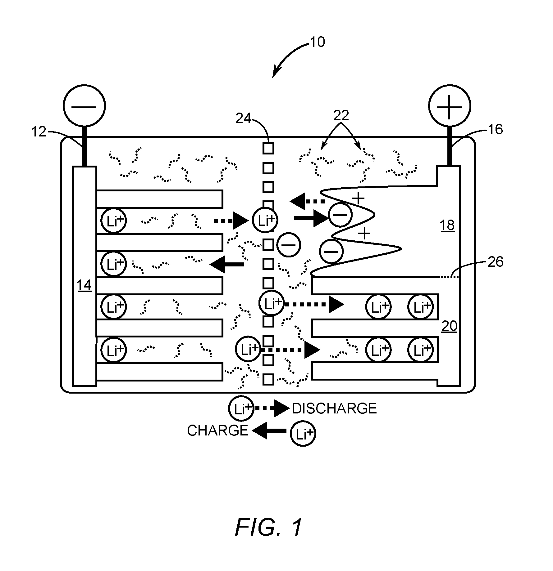
[0022] FIG. 1 is a diagram of a non-limiting, illustrative depiction of a lithium ion (Li-Ion) based hybrid electrochemical cell in accordance with the present disclosure.
[0023] FIG. 2 is a non-limiting, illustrative depiction of a line drawing of a sample of an interconnected corrugated carbon-based network (ICCN) that is usable to make up capacitor electrodes for hybrid electrochemical cells.
[0024] FIG. 3 is a non-limiting, illustrative depiction of a diagram depicting a Li-Ion based micro-hybrid electrochemical cell.
[0025] FIG. 4 is a non-limiting, illustrative depiction of a process flow diagram depicting fabrication of the micro-sized Li-Ion based hybrid electrochemical cell of FIG. 3.
[0026] FIG. 5 is a non-limiting, illustrative depiction of an embodiment suitable for realizing hybrid electrochemical cells of either nickel-cadmium (Ni--Cd) and/or nickel-metal hydride (Ni-MH) chemistries.
[0027] FIG. 6 is a non-limiting, illustrative depiction of a micro-sized hybrid electrochemical cell based on either Ni--Cd or Ni-MH chemistries.
[0028] FIG. 7 is a non-limiting, illustrative depiction of a process flow diagram illustrating fabrication of the micro-sized hybrid electrochemical cell of FIG. 6.
[0029] FIG. 8A is a charge-discharge graph of voltage versus time for a prior art Li-Ion capacitor.
[0030] FIG. 8B is a charge-discharge graph of voltage versus time for a prior art Li-Ion battery.
[0031] FIG. 8C is a non-limiting, illustrative depiction of a charge-discharge graph of an embodiment of a voltage versus time for a hybrid electrochemical cell of the present disclosure.
[0032] FIG. 9 is a non-limiting, illustrative depiction of a charge-discharge graph of voltage versus time for a hybrid electrochemical cell of the present disclosure that comprises redox active niobium pentoxide (Nb.sub.2O.sub.5).
[0033] FIG. 10A is a graph depicting a charge-discharge curve for a prior art nickel-carbon supercapacitor.
[0034] FIG. 10B is a graph depicting a charge-discharge curve for both a prior art Ni--Cd battery and a prior art Ni-MH battery.
[0035] FIG. 10C is a non-limiting, illustrative depiction of a charge-discharge graph of voltage versus time for embodiments of either of the Ni--Cd and the Ni-MH chemistries comprising hybrid electrochemical cells of the present disclosure.
[0036] FIG. 11 is a non-limiting, illustrative depiction of a Ragone plot comparing power density versus energy density for capacitors, supercapacitors, Li-Ion capacitors, batteries, and the hybrid electrochemical cells of the present disclosure.
[0037] FIG. 12A is a non-limiting, illustrative depiction of an implantable medical device having a hybrid electrochemical cell of the present disclosure integrated within.
[0038] FIG. 12B is a non-limiting, illustrative depiction of a smart card having a hybrid electrochemical cell of the present disclosure integrated within.
[0039] FIG. 12C is a non-limiting, illustrative depiction of a radio frequency identification (RFID) tag having a hybrid electrochemical cell of the present disclosure integrated within.
[0040] FIG. 12D is a non-limiting, illustrative depiction of a wireless sensor having a hybrid electrochemical cell of the present disclosure integrated within.
[0041] FIG. 12E is a non-limiting, illustrative depiction of a wearable device having a hybrid electrochemical cell of the present disclosure integrated within.
[0042] FIG. 12F is a non-limiting, illustrative depiction of a solar cell having a hybrid electrochemical cell of the present disclosure integrated with the solar cell to realize an energy harvesting system.
DETAILED DESCRIPTION
[0043] Upon reading the following description in light of the accompanying drawings, those skilled in the art will understand the concepts of the disclosure and will recognize applications of these concepts not particularly addressed herein. It should be understood that these concepts and applications are non-limiting and fall within the scope of the disclosure and the accompanying claims.
[0044] A feature of the subject matter described herein is a hybrid electrochemical cell. In certain embodiments, the hybrid electrochemical cells described herein comprise nickel-cadmium (Ni--Cd), nickel-metal hydride (Ni-MH) and/or lithium-ion (Li-Ion) batteries. FIG. 1, for example, depicts a non-limiting structure of a Li-Ion based hybrid electrochemical cell 10 in accordance with the present disclosure. The hybrid electrochemical cell 10 includes a first conductor 12 having a single portion 14 that is both a first capacitor electrode and a first battery electrode. In the Li-Ion based chemistry of the hybrid electrochemical cell 10, the first conductor 12 is negative and is doped with lithium ions. The hybrid electrochemical cell 10 includes a second conductor 16 having at least one portion that is a second capacitor electrode 18 and at least one other portion that is a second battery electrode 20. An electrolyte 22 is in contact with both the first conductor 12 and the second conductor 16. A separator 24 between the first conductor 12 and the second conductor 16 prevents physical contact between the first conductor 12 and the second conductor 16, while facilitating ion transport between the first conductor 12 and the second conductor 16. The second capacitor electrode 18 and the second battery electrode 20 are delineated by a horizontal dashed line 26 in FIG. 1. As shown, a ratio between the portion of the second capacitor electrode 18 and the second battery electrode 20 is about 1:1. However, it is to be understood that the ratio between the portion of the second capacitor electrode 18 and the second battery electrode 20 can range from 1:10 to 10:1 (inclusive of all ratios in between those endpoints, including but not limited to, 2:9, 3:8, 4:7, 5:6, 6:5, 7:4, 8:3, and 9:2). As the portion of the second capacitor electrode 18 increases relative to the second battery electrode 20, the power density of the hybrid electrochemical cell 10 increases and the energy density decreases. Likewise, as the portion of the second battery electrode 20 increases relative to the second capacitor electrode 18, the energy density of the hybrid electrochemical cell 10 increases and the power density decreases. The ratio of the second capacitor electrode 18 relative to the second battery electrode 20 is predetermined for a given application. For example, a larger ratio of the second capacitor electrode 18 relative to the second battery electrode 20 is desirable to capture energy quickly in a regenerative braking system, while a smaller ratio of the second capacitor electrode 18 relative to the second battery electrode 20 might be desirable for energizing a power tool such as a portable electric drill.
[0045] In understanding the hybrid electrochemical cell 10, it is helpful to note that a typical lithium ion battery comprises a graphite negative electrode and a layered metal oxide positive electrode. In contrast, a lithium ion capacitor is made of a graphite negative electrode and an activated carbon positive electrode. Since the negative electrode in both designs is graphite, these two devices can be integrated into one cell by connecting internally the battery and capacitor positive electrodes in parallel. The capacitor electrode would act as a buffer to prevent high rate charge and discharge of the battery. This can potentially extend the lifetime of the battery portion of the hybrid cell by a factor of ten, leading to energy storage systems that may never need to be replaced for the lifetime of a product being powered by the hybrid electrochemical cell 10. In addition, given that the positive electrodes of the battery and the capacitor have the same operating voltage and current collector, it is possible to blend them together in one positive electrode as shown in FIG. 1. As a result, the hybrid electrochemical cell 10, in certain embodiments, has only two electrodes instead of the four electrodes used in traditional power systems having battery and supercapacitor combinations. The simplified structure and design of the present disclosure's hybrid electrochemical cell 10 reduces the manufacturing cost and make powering hybrid automobiles energy efficient. Moreover, the hybrid electrochemical cell 10 combines battery technology and supercapacitor technology into a single cell using one type of electrolyte, thereby eliminating extra current collectors, electrolyte, and packaging. This means that the hybrid electrochemical cell 10 provides a higher energy density than traditional power systems that combine batteries and supercapacitors with interfacing electronics for power flow control between the batteries and supercapacitors. The hybrid electrochemical cell 10 is fabricated using commercial electrode materials, collectors, separators, binders, and electrolytes, which allows for fabrication processes that are readily scalable to industrial levels.
[0046] In some embodiments, the first battery electrode material used comprises graphite. Other materials are also suitable. For example, in some embodiments, the first battery electrode comprises hard carbon, silicon, composite alloys Sn(M)-based and Sn(O)-based, and combinations thereof.
[0047] In certain embodiments, the second battery electrode material comprises: lithium cobalt oxide, lithium manganese oxide, lithium nickel oxide,
[0048] lithium nickel manganese cobalt oxide, lithium nickel cobalt aluminum oxide, lithium titanium oxide, and/or lithium iron phosphate, and combinations thereof.
[0049] In some embodiments, the second capacitor electrode 18 is made of a material that comprises an electric double layer capacitor (EDLC) in which charge is stored in double layers. In some embodiments, the second capacitor electrode 18 comprises interconnected corrugated carbon-based network (ICCN) 28 or activated carbon. In yet other embodiments, the second capacitor electrode 18 is redox active to store charge via intercalation pseudo-capacitance. In at least one embodiment, the second capacitor electrode 18 comprises niobium pentoxide (Nb.sub.2O.sub.5).
[0050] In further or additional embodiments, provided is a lithium ion battery that comprises or consists of two electrodes and electrolyte solution providing a conductive medium for lithium ions to move between the electrodes. In certain applications, both electrodes allow lithium ions to move in and out of their interiors. In the charge reactions, in certain embodiments of the subject matter described herein, lithium ions are deintercalated from the positive material and intercalated into the negative material. Similarly, in some embodiments, the reverse happens on discharge. The intercalation and deintercalation of lithium ions, in certain applications, causes the flow of electrons in an external circuit (not shown).
[0051] Another advantage of the subject matter described herein are methods, devices, and systems that provide for the increased movement of ions, including for example, lithium ions, into and out of the electrodes. A problem with pure lithium ion batteries is the slow movement of lithium ions in and out of the battery electrodes. As described herein, in some applications, the insertion of a supercapacitor electrode in the lithium ion-based hybrid electrochemical cell 10 speeds up the charge-discharge process by storing charge via adsorption of ions on the surface of a carbon electrode or through fast redox reactions near the surface of an oxide electrode instead of the bulk of a layered battery material. For example, in a carbon supercapacitor electrode, the charge is stored in an electric double at the interface between the carbon and electrolyte. Here, and in these applications of the methods, devices, and systems described herein, an interface between the electrodes and electrolyte is thought of as an electrical double layer composed of the electrical charge at the surface of the carbon electrode itself and the charge of the ions disbursed in the solution at a small distance from the electrode surface. This electrical double layer is formed when a potential is applied to the electrode and causes a charging current (non-faradaic current) to pass through the hybrid electrochemical cell 10. These reactions are described below.
[0052] The following equations describe the charge storage mechanism of certain embodiments of the hybrid electrochemical cell 10, for example, when using graphite as the first battery electrode and lithiated metal oxide as the second battery electrodes and carbon as the second capacitor electrode. At the positive electrode charge storage occurs through a combination of double layer adsorption capacitance and lithium ion insertion.
##STR00001##
[0053] In this scheme, LiMO.sub.2 represents a metal oxide positive material, such as LiCoO.sub.2, x is a fraction 0<x<1. C is a high surface area form of carbon, e.sup.+ is a hole, and A.sup.- is an electrolyte anion, and (e.sup.+|A.sub.ads.sup.-) refers to an electric double layer (EDL) formed at the interface between the carbon electrode and electrolyte.
[0054] At the negative electrode, lithium ion insertion into and out of graphite is described by the following equation.
##STR00002##
[0055] FIG. 2 is a non-limiting illustration of a line drawing of a sample of an interconnected corrugated carbon-based network (ICCN) 28, which is made up of a plurality of expanded and interconnected carbon layers that include corrugated carbon layers such as a single corrugated carbon sheet 30. In one embodiment, each of the expanded and interconnected carbon layers comprises at least one corrugated carbon sheet that is one atom thick. In another embodiment, each of the expanded and interconnected carbon layers comprises a plurality of corrugated carbon sheets 30. In this specific example, the thickness of the ICCN 28, as measured from cross-sectional scanning electron microscopy (SEM) and profilometry, was found to be around about 7.6 .mu.m. In one embodiment, a range of thicknesses of the plurality of expanded and interconnected carbon layers making up the ICCN 28 is from around about 1 .mu.m to about 100 .mu.m. In some embodiments, the thickness of the plurality of expanded and interconnected carbon layers making up the ICCN 28 is from around about 2 .mu.m to about 90 .mu.m, from about 3 .mu.m to about 80 .mu.m, from about 4 .mu.m to about 70 .mu.m, from 5 .mu.m to about 60 .mu.m, from about 5 .mu.m to about 50 .mu.m, 5 .mu.m to about 40 .mu.m, 5 .mu.m to about 30 .mu.m, 5 .mu.m to about 20 .mu.m, 5 .mu.m to about 10 .mu.m, from about 5 .mu.m to about 9 .mu.m, or from about 6 .mu.m to about 8 .mu.m.
[0056] In some embodiments, hybrid electrochemical cells in accordance with the present disclosure are also made on a micro-scale which will enable a relatively large number of applications for a new generation of electronics. For example, a micro-hybrid electrochemical cell, in some embodiments, are integrated into implantable medical devices, smart cards, radio frequency identification (RFID) tags, wireless sensors, and even wearable electronics. Integrated micro-hybrid electrochemical cells, in some applications, also serve as a way to better extract energy from solar, mechanical, and thermal sources and thus make more efficient self-powered systems. Micro-hybrid electrochemical cells, in certain embodiments, are also fabricated on the backside of solar cells in both portable devices and rooftop installations to store power generated during the day for use after sundown, helping to provide electricity around the clock when connection to the grid is not possible. Each of these applications is made possible by the subject matter described herein based in part on the flexibility in size and shape of the micro-hybrid electrochemical cells described herein. Moreover, in further or additional embodiments, provided is a thin form factor for the battery that allows for thinner portable electronics.
[0057] FIG. 3 is a non-limiting diagram illustrating a lithium ion-based micro-hybrid electrochemical cell 32. The micro-hybrid electrochemical cell 32 includes a first conductor 34 having a single portion 36 that is both a first capacitor electrode and a first battery electrode. In the lithium ion-based chemistry of the micro-hybrid electrochemical cell 32, the first conductor 34 is negative and is doped with lithium ions. The micro-hybrid electrochemical cell 32 includes a second conductor 38 having at least one portion that is a second capacitor electrode 40 and at least one other portion that is a second battery electrode 42.
[0058] An electrolyte 44 is in contact with both the first conductor 34 and the second conductor 38. The second capacitor electrode 40 and the second battery electrode 42 each have electrode digits with a length L, a width W, and an interspace I. In an exemplary millimeter scale embodiment, the length L is around about 4800 .mu.m, the width W ranges from around about 330 .mu.m to around about 1770 .mu.m, and the interspace I is typically around about 150 .mu.m. While these dimensions are exemplary, it is to be understood that a further miniaturization of the width W of the electrode digits and the interspace I between the electrode digits in the micro-hybrid electrochemical cell 32 would reduce ionic diffusion pathways, thus leading to the micro-hybrid electrochemical cell 32 having even higher power density. In an exemplary centimeter scale embodiment, the length L is around about 1.2 cm, the width W ranges from around about 0.05 cm to around about 0.2 cm, and the interspace I is typically around about 0.05 cm.
[0059] In some embodiments, the micro-hybrid electrochemical cell 32 is integrated by growing porous positive and negative electrode materials on ICCN interdigitated patterns. In general, methods for producing the micro-hybrid electrochemical cell 32 having electrodes made of a patterned ICCN typically include an initial step of receiving a substrate having a carbon-based oxide film. Once the substrate is received, a next step involves generating a light beam having a power density sufficient to reduce portions of the carbon-based oxide film to an ICCN. Another step involves directing the light beam across the carbon-based oxide film in a predetermined pattern via a computerized control system while adjusting the power density of the light beam via the computerized control system according to predetermined power density data associated with the predetermined pattern. Exemplary light sources for generating the light beam include but are not limited to a 780 nm laser, a green laser, and a flash lamp. The light beam emission of the light sources may range from near infrared to ultraviolet wavelengths.
[0060] An exemplary process for fabricating the micro-hybrid electrochemical cell 32 is schematically illustrated in FIG. 4. In some embodiments, the ICCN pattern is created using a consumer-grade digital versatile disc (DVD) burner drive. In a first step, a graphite oxide (GO) dispersion in water is dropcast onto a DVD disc and dried in air to form a graphite oxide film 46 (step 100). A micro-pattern made with imaging or drafting software is directly printed onto the GO-coated DVD disc 48 (step 102). The GO film absorbs the energy from a laser 50 and is converted into an ICCN pattern. With the precision of the laser 50, the DVD burner drive renders the computer-designed pattern onto the GO film to produce the desired ICCN circuits. In certain applications, the ICCN pattern is designed to have three terminals: an ICCN supercapacitor-like electrode and two battery electrodes. In some embodiments, the capacity of the supercapacitor electrode is boosted by the electrophoretic deposition of activated carbon micro-particles.
[0061] In further or additional embodiments, anode and/or cathode materials are sequentially electrodeposited on the ICCN scaffold. Voltage-controlled and current-controlled electrodeposition is used to ensure conformal coating of the active materials throughout the three-dimensional (3D) structure of the ICCN. For example, manganese dioxide (MnO.sub.2) is electrodeposited on the ICCN microelectrodes making up the second battery electrode 42 (FIG. 3) that forms a portion of a cathode and is followed by a lithiation of MnO.sub.2 in molten lithium nitrate (LiNO.sub.3) and lithium hydroxide (LiOH) (step 104). In some embodiments, polyaniline is used as an alternative to the cathode material. Next, a nickel-tin alloy, silicon, or even graphite micro-particles are electrodeposited onto ICCN corresponding to the anode (step 106). To complete the micro-hybrid electrochemical cell 32, a drop of electrolyte 52 is added to provide ions that allow continuous electron flow when the micro-hybrid electrochemical cell 32 is under load (step 108).
[0062] In some embodiments, the micro-hybrid electrochemical cell 32 is realized using nickel-cadmium (Ni--Cd) and nickel-metal hydride (Ni-MH) chemistries in a similar manner to that of the lithium ion-based hybrid electrochemical cell 10 (see FIG. 1) except that the chemistry of Ni--Cd or Ni-MH batteries is combined with a Ni-carbon asymmetric supercapacitor.
[0063] FIG. 5 depicts a non-limiting structure for a hybrid electrochemical cell 54 for Ni--Cd and Ni-MH chemistries in accordance with the present disclosure. In some embodiments, the hybrid electrochemical battery cell 54 includes a first conductor 56 having a single portion 58 that is both a first capacitor electrode and a first battery electrode. In some embodiments, in either of the Ni--Cd and/or Ni-MH based chemistries of the hybrid electrochemical cell 54, the first conductor 56 is positive and includes nickel oxyhydroxide (NiOOH) that reduces to nickel hydroxide (Ni(OH).sub.2) during discharge. In some embodiments, the hybrid electrochemical cell 54 includes a second conductor 60 having at least one portion that is a second capacitor electrode 62 and at least one other portion that is a second battery electrode 64. In some embodiments, the ions that collect on the second battery electrode 64 comprise a metal hydride represented by X in the metal hydride case or Cd(OH).sub.2 represented by Y in the Ni--Cd case. In certain applications, an electrolyte 66 is in contact with both the first conductor 56 and the second conductor 60, whereby a separator 68 between the first conductor 56 and the second conductor 60 prevents physical contact between the first conductor 56 and the second conductor 60, while facilitating ion transport between the first conductor 56 and the second conductor 60. In some embodiments, the second capacitor electrode 62 and the second battery electrode 64 are delineated by a horizontal dashed line 69 in FIG. 5. As shown, a ratio between the portion of the second capacitor electrode 62 and the second battery electrode 64 is 1:1. However, it is to be understood that the ratio between the portion of the second capacitor electrode 62 and the second battery electrode 64 can range from 1:10 to 10:1 (inclusive of all ratios in between those endpoints, including but not limited to, 2:9, 3:8, 4:7, 5:6, 6:5, 7:4, 8:3, and 9:2).
[0064] In some embodiments, as the portion of the second capacitor electrode 62 increases relative to the second battery electrode 64, the power density of the hybrid electrochemical cell 54 increases and the energy density decreases. Likewise, in further or additional embodiments, as the portion of the second battery electrode 64 increases relative to the second capacitor electrode 62, the energy density of the hybrid electrochemical cell 54 increases and the power density decreases. In certain applications, the ratio of the second capacitor electrode 62 relative to the second battery electrode 64 is predetermined for a given application. For example, a larger ratio of the second capacitor electrode 62 relative to the second battery electrode 64 is desirable to capture energy quickly in a regenerative braking system, while a smaller ratio of the second capacitor electrode 62 relative to the second battery electrode 64 might be desirable for energizing a power tool such as a portable electric drill.
[0065] In certain applications this design uses a negative electrode made of activated carbon in which the charge is stored in the electric double layer, while the positive electrode is pseudocapacitive (typically NiOOH) where the charge is stored through redox reactions in the bulk of the material. An aqueous alkaline solution is used as an electrolyte in the same way as in Ni--Cd and Ni-MH batteries. Because the positive electrode in Ni--Cd and Ni-MH batteries is NiOOH, the same as in traditional Ni--Cd asymmetric supercapacitors, in certain embodiments, provided is an integration of both devices into one cell by connecting the battery and capacitor negative electrodes in parallel. In further or additional embodiments, also provided is a blend of the battery and capacitor negative electrodes into one electrode.
[0066] FIG. 6 is a non-limiting diagram depicting a micro-hybrid electrochemical cell 70 based on either Ni--Cd or Ni-MH chemistries. In some embodiments, the micro-hybrid electrochemical battery cell 70 includes a first conductor 72 having a single portion 74 that is both a first capacitor electrode and a first battery electrode. In further or additional embodiments, during fabrication of the micro-hybrid electrochemical cell 70, the first conductor 56 is positive and is doped with NiOOH for use with either Ni--Cd or Ni-MH chemistries. In some embodiments, the micro-hybrid electrochemical cell 70 includes a second conductor 76 having at least one portion that is a second capacitor electrode 78 and at least one other portion that is a second battery electrode 80. In some embodiments, an electrolyte 82 is in contact with both the first conductor 72 and the second conductor 76. For example, the second capacitor electrode 78 and the second battery electrode 80 each have electrode digits with a length L, a width W, and an interspace I. In an exemplary embodiment the length L is around about 4800 .mu.m, the width W ranges from around about 330 .mu.m to around about 1770 .mu.m, and the interspace I is typically around about 150 .mu.m. While these dimensions are exemplary, it is to be understood that a further miniaturization of the width W of the electrode digits and the interspace I between the electrode digits in the micro-hybrid electrochemical cell 70 would reduce ionic diffusion pathways, thus leading to the micro-hybrid electrochemical cell 70 having even higher power density.
[0067] Similar to the fabrication of the Li-Ion based micro-hybrid electrochemical cell 32, the micro-hybrid electrochemical cell 70, based on either Ni--Cd or Ni-MH chemistries, in certain embodiments is integrated by growing porous positive and negative electrode materials on ICCN interdigitated patterns. An exemplary process for fabricating the micro-hybrid electrochemical cell 70 is schematically illustrated in FIG. 7. Steps 100 and 102 are completed the same as shown in FIG. 4. However, new steps are added after step 102 to accommodate the Ni--Cd or Ni-MH chemistries to sequentially electrodeposit anode and cathode materials on the ICCN scaffold. As with the fabrication of Li-Ion based micro-hybrid electrochemical cell 32, voltage-controlled and current-controlled electrodeposition is used to ensure conformal coating of the active materials throughout the 3D structure of ICCN. A metal such as lanthanum nickel (LaNi.sub.5) or palladium (Pd) is electrodeposited on ICCN microelectrodes making up the second battery electrode 80 that forms a portion of an anode (step 110). Next, Cd(OH).sub.2 is added to the ICCN corresponding to the anode (step 112). To complete the micro-hybrid electrochemical cell 70, a drop of electrolyte 82 is added to provide ions that allow continuous electron flow when the micro-hybrid electrochemical cell 70 is under load (step 114).
[0068] The electrochemical reactions of the Ni-MH and Ni--Cd based hybrid electrochemical cells are described in the following:
[0069] Ni-MH based hybrid electrochemical cell [0070] The negative electrode
[0070] ##STR00003## [0071] On the positive electrode
##STR00004##
[0072] The metal, M, in the negative electrode of a Ni-MH cell, is actually a hydrogen storage alloy. It comes from a new group of intermetallic compounds which can reversibly store hydrogen. Many different compounds have been developed for this application, but the most extensively adopted is rare earth-based AB.sub.5-type alloys. In this type of alloy, the A component consists of one or more rare earth elements, and B is mainly composed of transition metals such as Ni, Co, Mn, and Al. The capacitor electrode stores charge in an electric double layer. (e.sup.-|A.sub.ads.sup.+) refers to an electric double layer (EDL) formed at the interface between the carbon electrode and electrolyte, where e.sup.- is an electron from the electrode side and A.sub.ads.sup.+ is a cation from the electrolyte side. In the Ni-MH hybrid electrochemical cell, nickel oxyhydroxide (NiOOH), is the active material in the charged positive electrode. During discharge, it reduces to the lower valence state, nickel hydroxide, Ni(OH).sub.2, by accepting electrons from the external circuit. These reactions reverse during charging of the cell.
[0073] Ni--Cd based hybrid electrochemical cell [0074] The negative electrode
[0074] ##STR00005## [0075] On the positive electrode
##STR00006##
[0076] In the Ni--Cd based hybrid electrochemical cell, the negative electrode consists of cadmium metal and high surface area carbons. During charge, Ni(OH).sub.2 is oxidized to the higher valence state and releases electrons to the external circuit. These electrons are stored in the negative electrode by reducing Cd(OH).sub.2 to elemental cadmium and in electric double layers.
[0077] FIG. 8A is a charge-discharge graph of voltage versus time for a prior art lithium ion capacitor. The charge rate and the discharge rate are relatively steep in comparison to a lithium ion battery charge rate and discharge rate shown in FIG. 8B. FIG. 8C is a non-limiting charge-discharge graph of voltage versus time for a hybrid electrochemical cell of the present disclosure. Notice that in this case, and in certain embodiments of the present disclosure, the hybrid electrochemical cell has charge rates and discharge rates that are commensurate with both the lithium ion capacitor and the lithium ion battery. As a result, the hybrid electrochemical cells of this disclosure share the best properties of both the lithium ion capacitor and the lithium ion battery and therefore can be thought of as being "super-batteries."
[0078] The shape of the charge-discharge graph of the hybrid electrochemical cell is controlled by the type of the second capacitor electrode. For example, FIG. 8C describes the case when using a double layer capacitor electrode such as ICCN 28 or activated carbon. However, when using redox active Nb.sub.2O.sub.5, the behavior is illustrated in FIG. 9. Other materials are also suitable.
[0079] FIG. 10A is a graph depicting a charge-discharge curve for a prior art nickel-carbon supercapacitor. In contrast, FIG. 10B is a graph depicting a charge-discharge curve for both a prior art Ni--Cd battery and a prior art Ni-MH battery. FIG. 10C is a non-limiting illustration of a charge-discharge graph of voltage versus time for either of the Ni--Cd and the Ni-MH chemistries for embodiments comprising hybrid electrochemical cells of the present disclosure. In essence, the charge-discharge graph of FIG. 10C can be thought of as the result of a combination of the electrochemical properties of nickel-carbon supercapacitor and Ni--Cd or Ni-MH battery.
[0080] A Ragone plot is useful to highlight the improved electrochemical storage ability of the hybrid electrochemical cells of the present disclosure. FIG. 11 is a Ragone plot comparing the performance of hybrid electrochemical cells with different energy storage devices designed for high-power demanding loads. The Ragone plot shows the gravimetric energy density and power density of the packaged cells for all the devices tested. The Ragone plot reveals a significant increase in performance for energy density in comparison to traditional supercapacitors. Remarkably, compared with lithium ion supercapacitors, hybrid electrochemical cells of certain embodiments of the subject matter described herein store up to ten times more energy and around about the same to slightly greater power density than lithium ion supercapacitors. For example, the hybrid electrochemical cells of the present disclosure have an energy density that ranges between 20 watt-hour/kilogram (Wh/kg) to around about 200 Wh/kg. Furthermore, although lithium ion batteries can provide high energy density, they have limited power performance that is nearly two orders of magnitude lower than the hybrid electrochemical cells of the present disclosure. For example, the hybrid electrochemical cells of the present disclosure have a power density that ranges between nearly 10.sup.3 watt/kilogram (W/kg) to about 10.sup.4 W/kg. This superior energy and power performance of the hybrid electrochemical hybrids will compete, completely replace, and/or complement batteries and supercapacitors, including lithium ion supercapacitors in a variety of applications. Moreover, a further miniaturization of the width of the micro-electrodes and the space between micro-electrodes in micro-hybrid electrochemical cells would reduce ionic diffusion pathways, thus leading to micro-hybrid electrochemical cells with even higher power density.
[0081] Applications for the disclosed embodiments of a micro-hybrid electrochemical cell are diverse. The following list is only exemplary. For example, FIG. 12A is a non-limiting, illustrative depiction of an implantable medical device 84 having the micro-hybrid electrochemical cell 70 integrated within. FIG. 12B is a non-limiting, illustrative depiction of a smart card 86 having the micro-hybrid electrochemical cell 70 integrated within. FIG. 12C is a non-limiting, illustrative depiction of a radio frequency identification (RFID) tag 88 having the micro-hybrid electrochemical cell 70 of the present disclosure integrated within. FIG. 12D is a non-limiting, illustrative depiction of a wireless sensor 90 having the micro-hybrid electrochemical cell 70 of the present disclosure integrated within. FIG. 12E is a non-limiting, illustrative depiction of the wearable device 92 having a micro-hybrid electrochemical cell 70 of the present disclosure integrated within. FIG. 12F is a non-limiting, illustrative depiction of a solar cell 94 having the micro-hybrid electrochemical cell 70 of the present disclosure integrated with the solar cell 94 to realize a self-powered system. Other self-powered systems that will benefit from integration with the present embodiments include but are not limited to vibrational type energy harvesting systems, wind energy harvesting systems, and temperature differential type energy harvesting systems.
[0082] Those skilled in the art will recognize improvements and modifications to the embodiments of the present disclosure. All such improvements and modifications are considered within the scope of the concepts disclosed herein and the claims that follow.
* * * * *
D00000
D00001
D00002
D00003
D00004
D00005
D00006

D00007

D00008

D00009

D00010

D00011

D00012

D00013

XML
uspto.report is an independent third-party trademark research tool that is not affiliated, endorsed, or sponsored by the United States Patent and Trademark Office (USPTO) or any other governmental organization. The information provided by uspto.report is based on publicly available data at the time of writing and is intended for informational purposes only.
While we strive to provide accurate and up-to-date information, we do not guarantee the accuracy, completeness, reliability, or suitability of the information displayed on this site. The use of this site is at your own risk. Any reliance you place on such information is therefore strictly at your own risk.
All official trademark data, including owner information, should be verified by visiting the official USPTO website at www.uspto.gov. This site is not intended to replace professional legal advice and should not be used as a substitute for consulting with a legal professional who is knowledgeable about trademark law.