Composite Battery Cell
YANG; Szu-Nan
U.S. patent application number 16/135519 was filed with the patent office on 2019-04-25 for composite battery cell. This patent application is currently assigned to PROLOGIUM TECHNOLOGY CO., LTD.. The applicant listed for this patent is PROLOGIUM HOLDING INC., PROLOGIUM TECHNOLOGY CO., LTD.. Invention is credited to Szu-Nan YANG.
| Application Number | 20190123326 16/135519 |
| Document ID | / |
| Family ID | 63685623 |
| Filed Date | 2019-04-25 |


View All Diagrams
| United States Patent Application | 20190123326 |
| Kind Code | A1 |
| YANG; Szu-Nan | April 25, 2019 |
COMPOSITE BATTERY CELL
Abstract
A composite battery cell includes a plurality of electricity supply elements connected to each other in series/parallel to form the electricity supply element groups. The electricity supply element groups are connected to each other in parallel/series and packed to form the battery cell with high capacity and high voltage. Each electricity supply element is an independent module and the electrolyte system does not circulate therebetween. There only have charges transferred rather than electrochemical reactions between the adjacent electricity supply elements. Therefore, the electrolyte decomposition would not occur result from the high voltage caused by connecting in series. Both series and parallel connection are made within the package of the battery cell to achieve high capacity and high voltage.
| Inventors: | YANG; Szu-Nan; (Taoyuan City, TW) | ||||||||||
| Applicant: |
|
||||||||||
|---|---|---|---|---|---|---|---|---|---|---|---|
| Assignee: | PROLOGIUM TECHNOLOGY CO.,
LTD. Taoyuan City TW PROLOGIUM HOLDING INC. Grand Cayman KY |
||||||||||
| Family ID: | 63685623 | ||||||||||
| Appl. No.: | 16/135519 | ||||||||||
| Filed: | September 19, 2018 |
| Current U.S. Class: | 1/1 |
| Current CPC Class: | H01M 2220/20 20130101; H01M 4/62 20130101; H01M 10/425 20130101; H01M 10/0562 20130101; H01M 10/0565 20130101; H01M 2/168 20130101; H01M 2/08 20130101; H01M 2/1077 20130101; H01M 2300/0082 20130101; H01M 10/0413 20130101; H01M 2/1686 20130101; H01M 2/206 20130101; H01M 10/0563 20130101; H01M 2/0237 20130101; H01M 2/027 20130101 |
| International Class: | H01M 2/16 20060101 H01M002/16; H01M 2/08 20060101 H01M002/08; H01M 4/62 20060101 H01M004/62; H01M 10/0562 20060101 H01M010/0562; H01M 10/0565 20060101 H01M010/0565; H01M 10/0563 20060101 H01M010/0563 |
Foreign Application Data
| Date | Code | Application Number |
|---|---|---|
| Oct 20, 2017 | TW | 106136071 |
Claims
1. A composite battery cell, comprising: a plurality of electricity supply element groups electrically connected to each other in parallel, each of the electricity supply element group includes a plurality of electricity supply elements electrically connected to each other in series, wherein each of the electricity supply elements serves as an independent module and an electrolyte system of each electricity supply element does not circulate therebetween; wherein a charge transfer is occurred between the adjacent electricity supply elements without electrochemical reactions; and a pack case, housing the electricity supply element groups.
2. The composite battery cell of claim 1, wherein the electrolyte system is a gel electrolyte, a liquid electrolyte, a solid electrolyte or a combination thereof.
3. The composite battery cell of claim 1, wherein the electricity supply element comprising: a separator; two active material layers, disposed on two sides of the separator respectively, and the electrolyte system impregnated therein; two current collectors, disposed on outer sides of the active material layers respectively; and a sealing layer, disposed between the edges of the two current collectors to adhere the two current collectors and seal the electrolyte system therebetween.
4. The composite battery cell of claim 3, wherein within the electricity supply element group, only the outer current collectors of the outermost two electricity supply elements include an electrode tab respectively.
5. The composite battery cell of claim 4, wherein the electrode tabs with the same polarity of the electricity supply element groups are connected to a conductive lead.
6. The composite battery cell of claim 5, wherein the conductive lead extends to expose from the pack case.
7. The composite battery cell of claim 5, further comprising a printed circuit board (PCB) module connected to the conductive lead and packed within the pack case.
8. The composite battery cell of claim 3, wherein each the electricity supply element of the electricity supply element group is directly contacted to the current collector of the adjacent electricity supply element via the current collector to form electrically connection.
9. The composite battery cell of claim 8, wherein the electricity supply element is directly contacted to the current collector of the adjacent electricity supply element via the current collector with different polarity to form electrically connection in series.
10. The composite battery cell of claim 3, wherein the sealing layer of the electricity supply element comprises two modified silicone layer and a silicone layer disposed therebetween.
11. The composite battery cell of claim 1, wherein the pack case is a polymer film, an aluminum foil or a metal can.
12. A composite battery cell, comprising: a plurality of electricity supply element groups electrically connected to each other in series, each of the electricity supply element group includes a plurality of electricity supply elements electrically connected to each other in parallel, wherein each of the electricity supply elements serves as an independent module and an electrolyte system of each the electricity supply element does not circulate therebetween; wherein a charge transfer is occurred between the adjacent electricity supply elements without electrochemical reactions; and a pack case, housing the electricity supply element groups.
13. The composite battery cell of claim 12, wherein the electrolyte system is a gel electrolyte, a liquid electrolyte, a solid electrolyte or a combination thereof.
14. The composite battery cell of claim 12, wherein the electricity supply element comprising: a separator; two active material layers, disposed on two sides of the separator respectively, and the electrolyte system impregnated therein; two current collectors, disposed on outer sides of the active material layers respectively; and a sealing layer, disposed between the edges of the two current collectors to adhere the two current collectors and seal the electrolyte system therebetween.
15. The composite battery cell of claim 14, wherein each of the current collectors of the electricity supply elements includes an electrode tab respectively.
16. The composite battery cell of claim 15, wherein the electrode tabs with the same polarity of the electricity supply elements of the electricity supply element group are connected to form electrically connection in parallel.
17. The composite battery cell of claim 15, wherein the electrode tabs of the outermost two electricity supply element groups are connected to a conductive lead.
18. The composite battery cell of claim 17, wherein the conductive lead extends to expose from the pack case.
19. The composite battery cell of claim 17, further comprising a printed circuit board (PCB) module connected to the conductive lead and packed within the pack case.
20. The composite battery cell of claim 15, wherein each of the electricity supply element of the electricity supply element group is directly contacted to the current collector of the adjacent electricity supply element via the current collector to form electrically connection.
21. The composite battery cell of claim 14, wherein the outermost electricity supply element of the electricity supply element group is directly contacted to the outermost current collector of the adjacent electricity supply element group to form electrically connection.
22. The composite battery cell of claim 21, wherein the electricity supply element groups are connected via the current collectors with different polarity to form electrically connection in series.
23. The composite battery cell of claim 14, wherein the sealing layer of the electricity supply element comprises two modified silicone layer and a silicone layer disposed therebetween.
24. The composite battery cell of claim 12, wherein the pack case is a polymer film, an aluminum foil or a metal can.
Description
CROSS REFERENCES TO RELATED APPLICATIONS
[0001] The present application claims priority to Taiwanese Patent Application 106136071 filed in the Taiwanese Patent Office on Oct. 20, 2017, the entire contents of which is being incorporated herein by reference.
BACKGROUND OF THE INVENTION
Field of Invention
[0002] The present invention relates to a battery cell, in particular to a composite battery cell formed by independent modular electricity supply elements, which both series and parallel connection are made within the package of the battery cell to achieve high capacity and high voltage.
Related Art
[0003] In recent years, with the increase of air pollution and global warming, electric vehicles have been given high expectations to replace existing combustible fuel vehicles to reduce the environmentally harmful effects of carbon dioxide. At present, the battery system is still the key point of the pure electric vehicles. The battery system for the electric vehicles is formed by several battery cells, connected to each other in series, in parallel or the combinations to achieve necessary capacity and voltage for the electric vehicles.
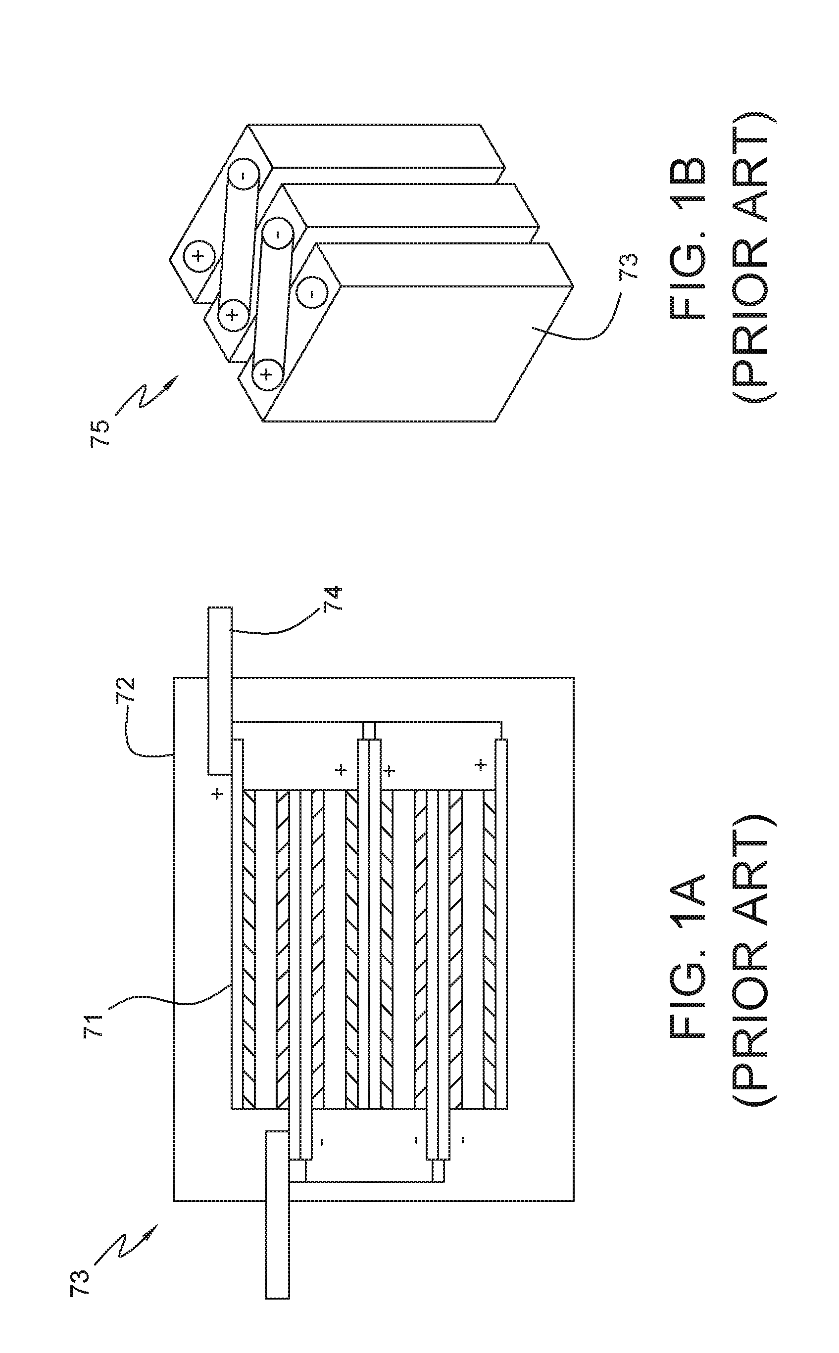
[0004] Please refer to FIGS. 1A and 1B, which is the most common practice, a plurality of battery elements 71 are connected to each other in parallel. Then a case 72 is used to pack the battery elements 71 to form the battery cell 73. The conductive lead 74 exposed from the case 72 is used to be externally connected in series to achieve a high enough voltage to form the battery system 75 for the electric vehicles. Alternative method is using the case 72 to house a plurality of battery elements 71. The electrolyte is filled within the case 72. Please see FIGS. 2A and 2B, the battery elements 71 are internally connected to each other in series to increase the voltage. Then the conductive lead 74 is used to be externally connected in parallel to achieve enough capacity to form the battery system 77 for the electric vehicles. However, the maximum permissible voltage of the electrolyte is usually 5V only. The voltage is increased result from the internally connected in series. And, the electric field distribution is not uniform due to the internal structure and arrangement. Once the voltage is over the maximum permissible voltage, the electrolyte decomposition would be occurred to make the battery system 77 fail. More seriously, it may cause the battery system 77 explosion. Therefore, there does not have similar products on the market.
[0005] The U.S. patent application NO. 2004/0091771 provides a common current collector is used by the two adjacent cells to form a bipolar battery to overcome the problem of the electrolyte decomposition. The design lacks flexibility due to the connection in series with the common current collector. It only can be applied in internal connection in series. Also, the external connection is needed to connect a plurality of bipolar batteries in parallel to form the assembled battery system.
[0006] Regardless of the above method, it is limited by the structural problems of the battery cell and the internal battery unit. The external connection in series is necessary to achieve enough voltage to form the battery system when the connection in parallel within the battery cell is adapted. Also, the external connection in parallel is necessary to achieve enough high capacity to form the battery system when the connection in series within the battery cell is adapted. The external connection is usually used the wire bonding, the metal lead, or the metal bar, which may increase the resistance of the battery system and lower the performance, and reliability and safety are reduced. Moreover, the volumetric energy density would be decreased due to the space occupied by the external connection.
SUMMARY OF THE INVENTION
[0007] It is an objective of this invention to provide a composite battery cell to overcome the forgoing shortcomings. Both series and parallel connection are made within the package of the battery cell to achieve high capacity and high voltage. Therefore, the shortcomings of the conventional battery system, such as lower performance and decreased volumetric energy density caused by the external connection, can be eliminated.
[0008] Also, it is another objective of this invention to provide a composite battery cell composed of the electricity supply elements. The charge transfer is occurred between the adjacent electricity supply elements without electrochemical reactions. The composite battery cell could be formed by the electricity supply elements electrically connected to each other both in series and in parallel. Therefore, high voltage is achieved without being limited by the maximum permissible voltage of the electrolyte system to increase volumetric energy density and voltage.
[0009] In order to implement the abovementioned, this invention discloses a composite battery cell, which includes a plurality of electricity supply element groups. The electricity supply element groups are connected to each other in parallel/series and packed by a pack case to form the composite battery cell. Each electricity supply element group is formed by a plurality of electricity supply elements connected to each other in series/parallel. And the electricity supply element include a separator, two active material layers, two current collectors, the electrolyte system and a sealing layer. The active material layers are disposed on the two sides of the separator, respectively, and the current collectors are disposed on outer sides of the active material layers, respectively. The electrolyte system impregnated within the active material layers, and the sealing layer is disposed between the edges of the two current collectors to adhere the two current collectors and seal the electrolyte system therebetween. Each electricity supply element is an independent module and the electrolyte system does not circulate therebetween. There only have charges transferred rather than electrochemical reactions between the adjacent electricity supply elements. Therefore, both series and parallel connection could be made within the package of the battery cell without being limited by the maximum permissible voltage of the electrolyte system.
[0010] On the other hand, the electricity supply elements are connected to each other via the current collectors and the electricity supply element groups are connected to each other via the current collectors. The contact area is much larger than the contact area of conventional method, such as wire bonding. Therefore the internal resistance of the battery cell is greatly reduced. The performance loss of the battery cell almost can be ignored and it would be considered that the performance of the battery cell does not decline. Also, due to the internal resistance is very low, the excellent charging/discharging speed efficiency and low heat generation are achieved. Therefore, the heat dissipation mechanism could be simplified. The whole system is easy to manage and control, and reliability and safety are improved.
[0011] Further scope of applicability of the present invention will become apparent from the detailed description given hereinafter. However, it should be understood that the detailed description and specific examples, while indicating preferred embodiments of the invention, are given by way of illustration only, since various changes and modifications within the spirit and scope of the invention will become apparent to those skilled in the art from this detailed description.
BRIEF DESCRIPTION OF THE DRAWINGS
[0012] The present invention will become more fully understood from the detailed description given hereinbelow illustration only, and thus are not limitative of the present invention, and wherein:
[0013] FIGS. 1A and 1B illustrate the first embodiment of conventional the battery cell and battery system.
[0014] FIGS. 2A and 2B illustrate the second embodiment of conventional the battery cell and battery system.
[0015] FIG. 3 illustrates the cross-sectional view of the electricity supply element of the composite battery cell of this invention.
[0016] FIG. 4 illustrates the cross-sectional view of another embodiment of the sealing layer of the electricity supply element of the composite battery cell of this invention.
[0017] FIG. 5A illustrates the first embodiment of the electricity supply element group of the composite battery cell of this invention.
[0018] FIG. 5B illustrates the second embodiment of the electricity supply element group of the composite battery cell of this invention.
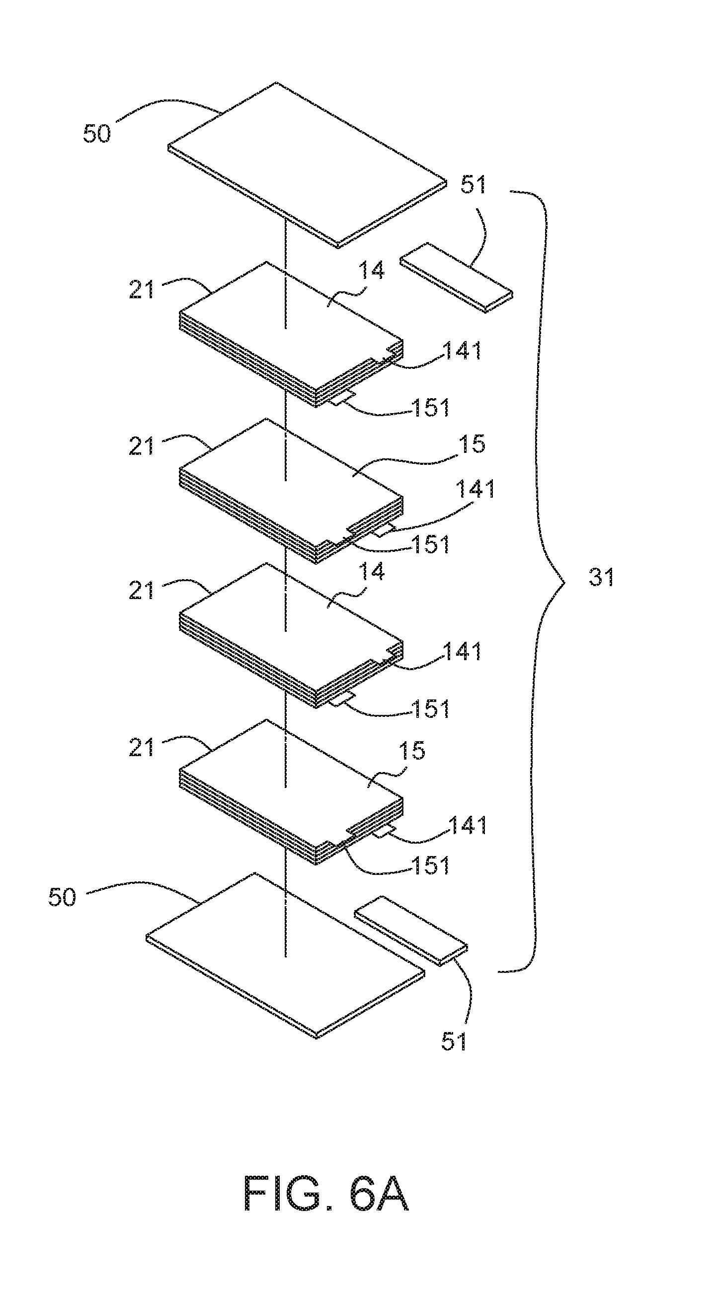
[0019] FIG. 6A illustrates the first embodiment of the composite battery cell of this invention.
[0020] FIG. 6B illustrates the second embodiment of the composite battery cell of this invention.
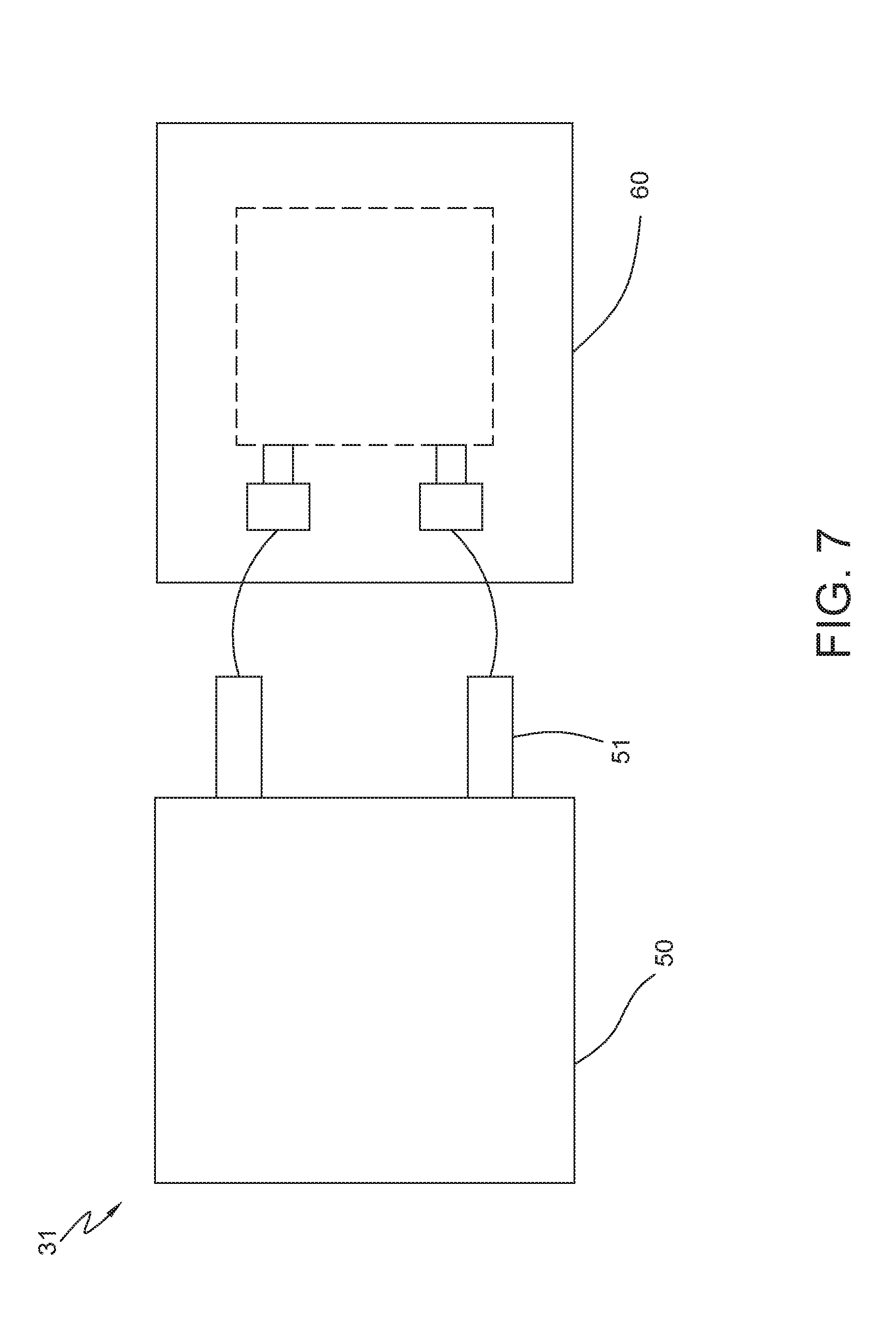
[0021] FIG. 7 illustrates the respective view of the composite battery cell of this invention, which is connected to a PCB module.
[0022] FIG. 8A illustrates the respective view of first embodiment of the composite battery cell of this invention, which integrated the PCB module into the pack case.
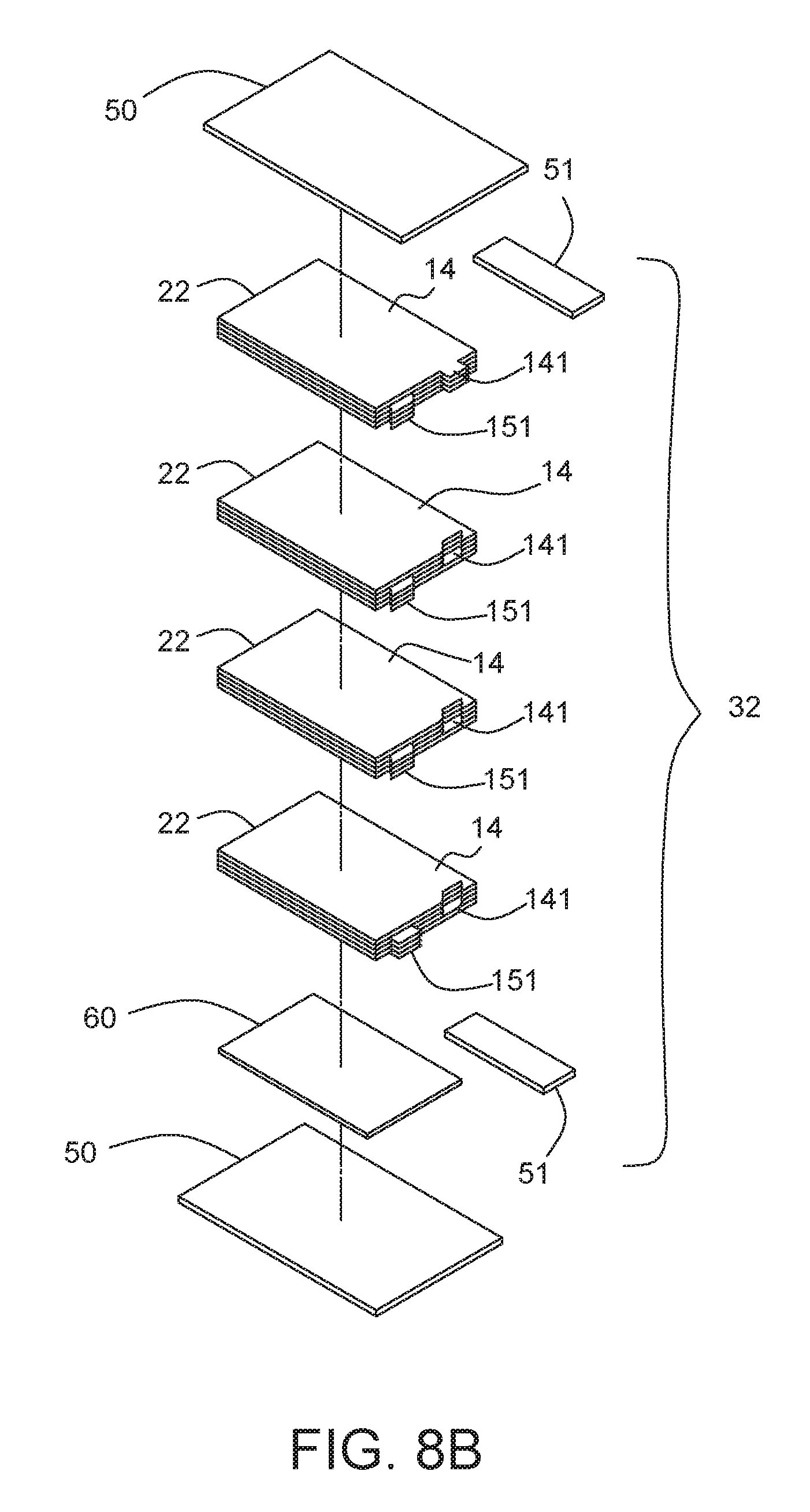
[0023] FIG. 8B illustrates the respective view of second embodiment of the composite battery cell of this invention, which integrated the PCB module into the pack case.
DETAILED DESCRIPTION OF THE INVENTION
[0024] The invention provides a composite battery cell including a plurality of electricity supply element groups electrically connected to each other in parallel or in series. Each electricity supply element group includes a plurality of electricity supply elements electrically connected to each other in series or in parallel. Therefore, both series and parallel connection are made within the package of the battery cell. It is quite different from conventional battery cell, which only can make either series or parallel connection within the package and make parallel or series connection outside the battery cell to form necessary battery system. Moreover, the electricity supply element of the present invention serves as an independent module. And the electrolyte system of each electricity supply element does not circulate therebetween.
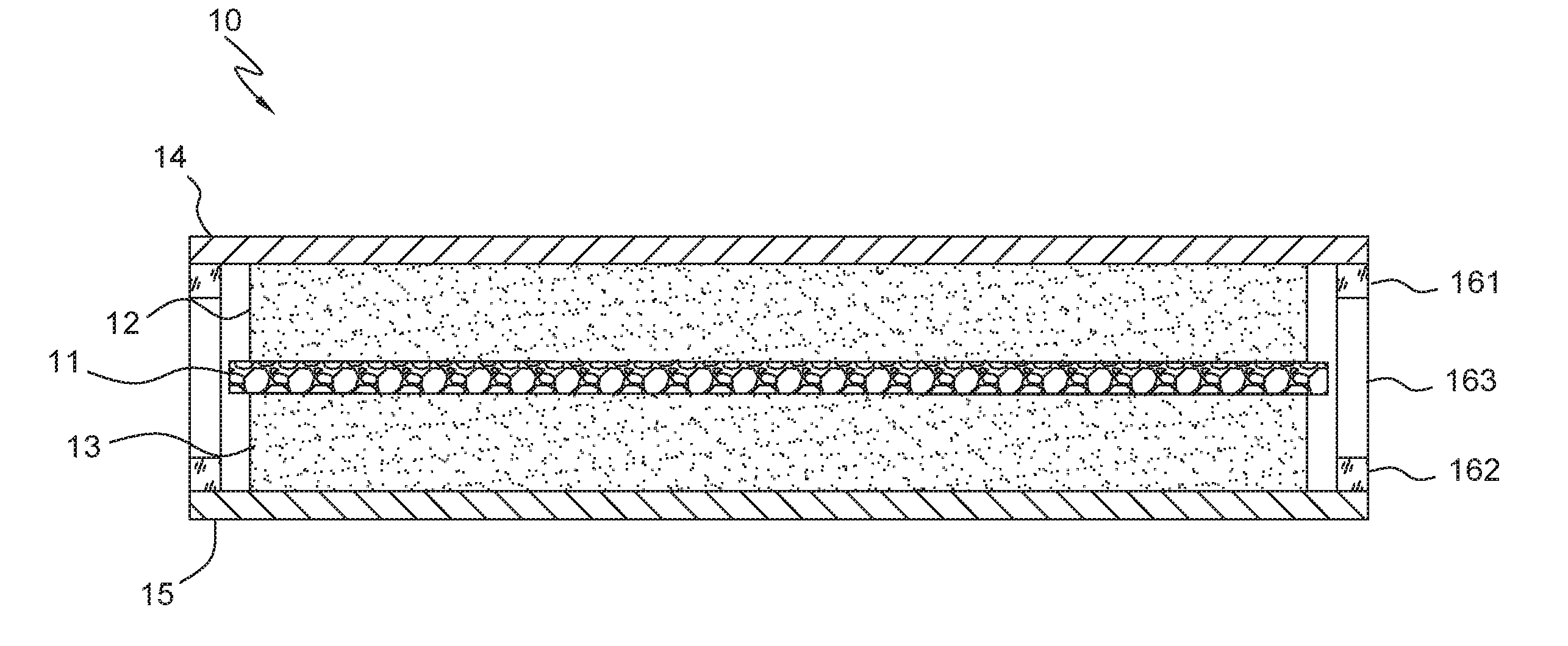
[0025] FIG. 3 illustrates the cross-sectional view of the electricity supply element of the composite battery cell of this invention. The electricity supply element 10 of this invention includes a separator 11, two active material layers 12, 13, two current collectors 14, 15, an electrolyte system and a sealing layer 16. The materials of the separator 11 include the polymers, the ceramics or the glass fibers. Also, the separator 11 has the holes to permit ion migration. The holes are formed by through holes, ant holes, or porous material, and may be further filled with ceramic insulation materials. The ceramic insulation materials include particulates of TiO.sub.2, Al.sub.2O.sub.3, SiO.sub.2 with nanometer and micrometer scale, or alkylation. The holes may be further filled with a polymer adhesive, which may be Polyvinylidene fluoride (PVDF), polyvinylidene fluoride co-hexafluoropropylene (PVDF-HFP), Polytetrafluoroethene (PTFE), acrylic acid glue, epoxy resin, polyethylene oxide (PEO), polyacrylonitrile (PAN), and polyimide (PI).
[0026] The active material layers 12, 13 are disposed on two sides of the separator 11 respectively, and the electrolyte system impregnated therein. The electrolyte system is a solid electrolyte, a liquid electrolyte, a gelled electrolyte, or the combination thereof. Therefore, the processes that the chemical energy is converted into electrical energy, discharging, and the electrical energy is converted into chemical energy, charging, may be carried out. The ion migration and transport are achieved. The electric charges are transmitted via the current collectors 14, 15, which are disposed on outer sides of the active material layers 12, 13, respectively. The materials of the current collectors 14, 15 are copper (Cu), Aluminum (Al), or nickel (Ni), tin (Sn), silver (Ag), gold (Au), or an alloy comprised of at least one of the foregoing metals.
[0027] The materials of the sealing layer 16 include the epoxy, Polyethylene (PE), Polypropylene (PP), Polyurethane (PU), thermoplastic polyimide (TPI), silicone, acrylic resin and/or ultraviolet light curing adhesive. The sealing layer 16 is disposed between the edges of the two current collectors 14, 15 to adhere the two current collectors 14, 15 and seal the electrolyte system therebetween to avoid leakage and prevent to circulate between adjacent electricity supply elements 10. Therefore, the electricity supply element 10 serves as an independent, sealed and complete module, which can generate power independently.
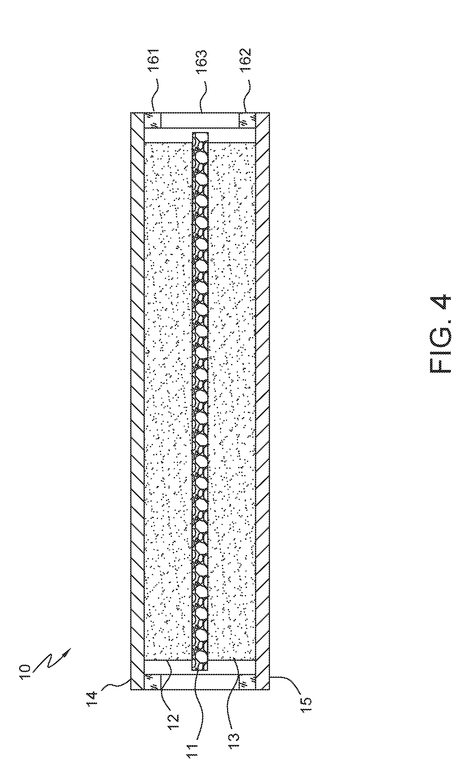
[0028] To enhance adhesion of the sealing layer 16, the sealing layer 16 may including two modified silicone layers 161, 162 and a silicone layer 163 disposed between the two modified silicone layers 161, 162. The modified silicone layers 161, 162 may be modified by adjusting a proportion of condensation-type silicone and addition-type silicone to enhance adhesion of different materials, i.e. the materials of the current collectors 14, 15 and the silicone layer 163. Therefore, the adhesion between the interfaces of the current collectors 14, 15 and the sealing layer 16 is enhanced. The overall appearance is more complete and the production yield is improved. Also, due to the sealing layer 16 is made of silicone, the moisture can be blocked from the outside and the polar solvent and the complexing agent can be blocked from the inside to make the package structure more complete.
[0029] The electricity supply element group includes a plurality of electricity supply elements 10 electrically connected to each other. Please refer to FIG. 5A, which illustrates the first embodiment of the electricity supply element group of the composite battery cell of this invention.
[0030] The electricity supply element group 21 includes a plurality of electricity supply elements 10 electrically connected to each other in series. Due to the outermost layer of the electricity supply elements 10 is the current collectors 14, 15, the adjacent electricity supply elements may form electrically connection by direct contact, such as overlapping, of the current collectors 14, 15. The current collectors 14, 15 with different polarity are contacted to form the electrical connection in series. For example, as shown in FIG. 5A, when the current collector 14 is a positive current collector and the current collector 15 is a negative current collector, the current collector 15 of the outermost electricity supply elements 10 can directly contact to the current collector 14 of the next electricity supply elements 10. Also, the current collector 15 of this electricity supply elements 10 can directly contact to the current collector 14 of the next electricity supply elements 10, sequentially. Therefore, the electricity supply element group 21 with the electricity supply elements 10 electrically connected to each other in series would be formed. The electricity supply element 10 serves as an independent module. The electrolyte system of each electricity supply element 10 does not circulate therebetween. Therefore, the charge transfer is occurred between the current collectors 14, 15 of the adjacent electricity supply elements without electrochemical reactions, i.e. without ion migration and transport. The high voltage caused by the electricity supply elements 10 connected in series does not affect the electrolyte system inside the individual electricity supply elements 10. The voltage affect the electrolyte system is only the individual voltage inside the electricity supply elements 10. Hence, the electricity supply element group 21 could be formed by the electricity supply elements 10 electrically connected to each other in series to achieve high voltage without being limited by the maximum permissible voltage of the electrolyte system, which is usually 5V.
[0031] Then, the electricity supply element groups 21 with the electricity supply elements 10 electrically connected to each other in series, may be connected each other to form the composite battery cell or the external connection, which is described later in detail. The outer current collectors 14, 15 of the outermost electricity supply element 10 include an electrode tabs 141, 151 respectively. In other words, the current collector 14 of the uppermost electricity supply element 10 has the electrode tab 141, and the current collector 15 of the lowermost electricity supply element 10 has the electrode tab 145, as shown in FIG. 5A. The other current collectors may not include the electrode tabs.
[0032] Please refer to FIG. 6A, the composite battery cell 31 is formed by the electricity supply element groups 21, which is shown in FIG. 5A. Due to the electricity supply element group 21 with the electricity supply elements 10 electrically connected to each other in series, the composite battery cell 31 of this embodiment includes a plurality of electricity supply element groups 21 electrically connected in parallel. In other words, the electricity supply element groups 21 are inverted alternately face up and face down to stack. The current collectors 14, 15 of the outermost electricity supply elements 10 are directly contacted to achieve electrical connection, and the electrode tabs 141, 151 with the same polarity of the electricity supply element groups 21 are connected to a corresponding conductive lead 51. The pack case 50 is used to house the electricity supply element groups 21. The pack case 50 may be a polymer film to prevent short circuit. Also, the pack case 50 may be an aluminum foil or a metal can. After packed, the conductive lead 51 extends to expose from the pack case 50, please refer to FIG. 7. A printed circuit board (PCB) module 60 may be used to be connected to the conductive lead 51 for management and supply. The shape and the form of the pack case 50 are just illustrated. The other different forms, such as bags or boxes, may also be applied.
[0033] Therefore, both series and parallel connection are made within the package, the pack case 50, of the composite battery cell 31 to achieve high capacity and high voltage. It is quite different from conventional battery cell, see FIGS. 2A and 2B, which only can make series connection within the package and make parallel connection outside the battery cell to form necessary battery system. On the other hand, the composite battery cell 31 of the present invention may almost be served as the conventional battery system. However, due to the external connections are omitted, the occupied space is decreased and the volumetric energy density is increased. Furthermore, it is convenient to manage.
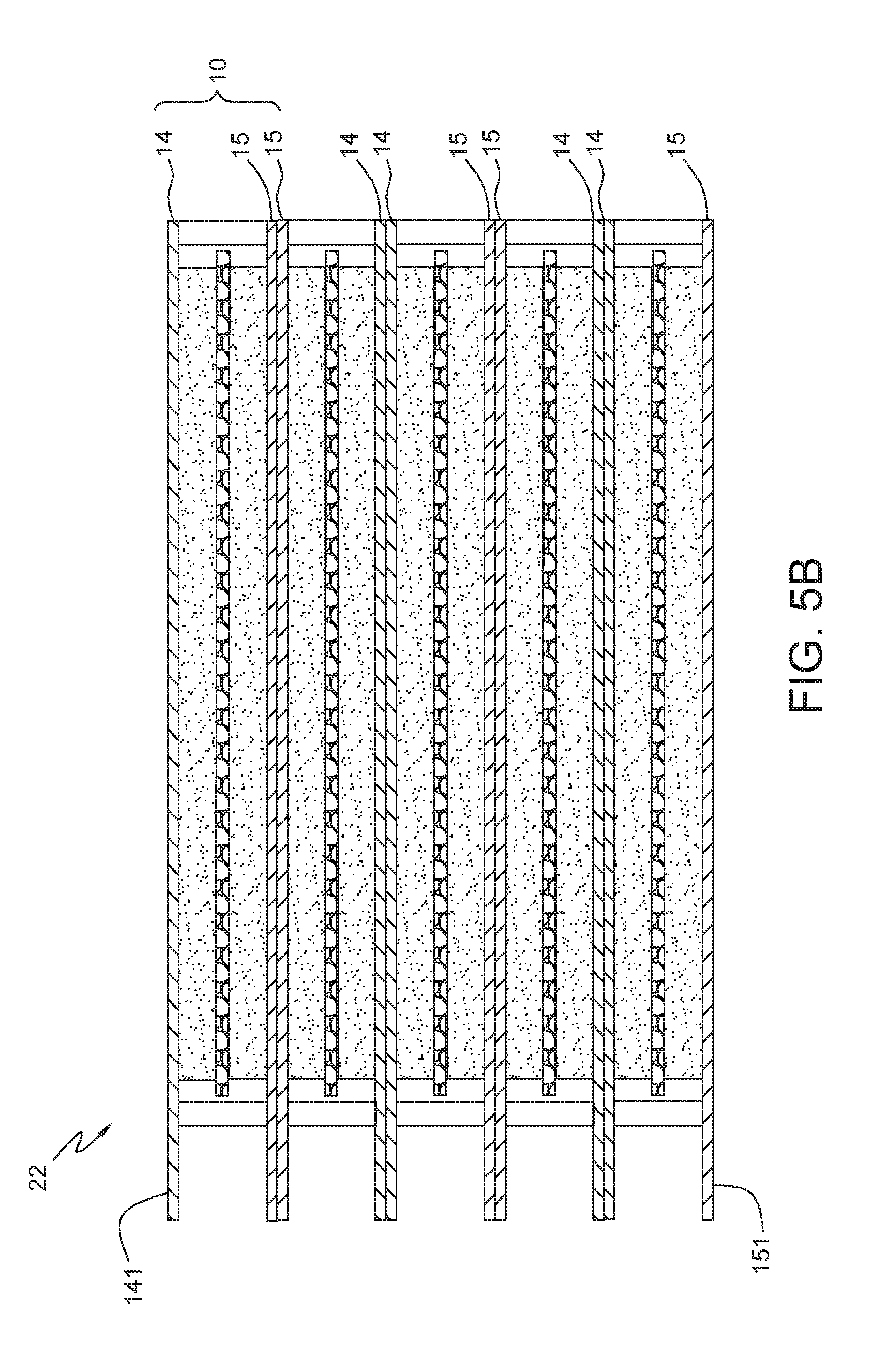
[0034] Please refer to FIG. 5B, which illustrates the second embodiment of the electricity supply element group of the composite battery cell of this invention. The electricity supply element group 22 includes a plurality of electricity supply elements 10 electrically connected to each other in parallel. Due to the outermost layer of the electricity supply elements 10 is the current collectors 14, 15, the adjacent electricity supply elements may form electrically connection by direct contact of the current collectors 14, 15. Each current collectors 14, 15 of the electricity supply element 10 include an electrode tabs 141, 151 respectively. The electrode tabs 141, 151 with the same polarity of the electricity supply elements 10 of the electricity supply element group 22 are connected to form electrically connection in parallel, via folding to contact or welding. For example, as shown in FIG. 5B, when the current collector 14 is a positive current collector and the current collector 15 is a negative current collector, the current collector 15 of the outermost electricity supply elements 10 can directly contact to the current collector 15 of the next electricity supply elements 10. Also, the current collector 14 of this electricity supply elements 10 can directly contact to the current collector 14 of the next electricity supply elements 10, sequentially. Then, the electrode tabs 141, 151 are used to form electrical connection in parallel. The electricity supply element 10 serves as an independent module. The electrolyte system of each electricity supply element 10 does not circulate therebetween. Therefore, the charge transfer is occurred between the current collectors 14, 15 of the adjacent electricity supply elements without electrochemical reactions, i.e. without ion migration and transport.
[0035] Moreover, please refer to FIG. 6B, the composite battery cell 32 is formed by the electricity supply element groups 22, which is shown in FIG. 5B. Due to the electricity supply element group 22 with the electricity supply elements 10 electrically connected to each other in parallel, the composite battery cell 32 of this embodiment includes a plurality of electricity supply element groups 22 electrically connected in series. In other words, the electricity supply element groups 22 are stacked in the same orientation. The current collectors 14, 15 of the outermost electricity supply elements 10 are directly contacted with the different polarity to achieve electrical connection. The pack case 50 is used to house the electricity supply element groups 22. The pack case 50 may be a polymer film to prevent short circuit. Also, the pack case 50 may be an aluminum foil or a metal can. The electrode tabs 141, 151 of each electricity supply element group 22 are folded to contact and electrically connect to the current collectors 14, 15 with the same polarity of the adjacent electricity supply element group 22. Only one set of the electrode tabs 141, 151 of the outermost electricity supply element group 22 are kept to connect to the conductive lead 51. After packed, the conductive lead 51 extends to expose from the pack case 50, please refer to FIG. 7. Therefore, both series and parallel connection are made within the package, the pack case 50, of the composite battery cell 32 to achieve high capacity and high voltage. It is quite different from conventional battery cell, see FIGS. 1A and 1B, which only can make parallel connection within the package and make connection in series outside the battery cell to form necessary battery system. On the other hand, the composite battery cell 32 of the present invention may almost be served as the conventional battery system. However, due to the external connections are omitted, the occupied space is decreased and the volumetric energy density is increased. Furthermore, it is convenient to manage.
[0036] Also, the PCB module 60 may be packed within the pack case 50 for convenient use, please refer to FIGS. 8A and 8B. Such that the external PCB module 60 are not necessary for the composite battery cell 31, 32. It is convenient to use and flexible to design.
[0037] Accordingly, the composite battery cell of the present invention includes a plurality of electricity supply elements connected in series/parallel to form the electricity supply element groups. The electricity supply element groups are connected in parallel/series and packed to form the battery cell with high capacity and high voltage. Due to both series and parallel connection are made within the package of the battery cell, the external connection, in series, in parallel or the combinations, of the conventional battery cell are not necessary. Therefore, the resistance would not be increased caused by the external connection. The discharge performance is improved, and reliability and safety are significantly improved.
[0038] Furthermore, because the electricity supply element serves as an independent module, the electrolyte system of each electricity supply element does not circulate therebetween. Therefore, the charge transfer is occurred between the adjacent electricity supply elements without electrochemical reactions, i.e. without ion migration and transport. The electrolyte decomposition would not occur result from the high voltage to improve the safety. Also, the electricity supply element group is formed by the directly contact of the current collectors of the electricity supply elements. The resistance of the whole structure is very low, and the excellent charging/discharging speed efficiency and low heat generation are achieved. Therefore, the heat dissipation mechanism could be simplified. The whole system is easy to manage and control.
[0039] The invention being thus described, it will be obvious that the same may be varied in many ways. Such variations are not to be regarded as a departure from the spirit and scope of the invention, and all such modifications as would be obvious to one skilled in the art are intended to be included within the scope of the following claims.
* * * * *
D00000
D00001
D00002
D00003
D00004
D00005
D00006
D00007
D00008
D00009
D00010
D00011
XML
uspto.report is an independent third-party trademark research tool that is not affiliated, endorsed, or sponsored by the United States Patent and Trademark Office (USPTO) or any other governmental organization. The information provided by uspto.report is based on publicly available data at the time of writing and is intended for informational purposes only.
While we strive to provide accurate and up-to-date information, we do not guarantee the accuracy, completeness, reliability, or suitability of the information displayed on this site. The use of this site is at your own risk. Any reliance you place on such information is therefore strictly at your own risk.
All official trademark data, including owner information, should be verified by visiting the official USPTO website at www.uspto.gov. This site is not intended to replace professional legal advice and should not be used as a substitute for consulting with a legal professional who is knowledgeable about trademark law.