Pattern Formation Method
SAWABE; Tomoaki ; et al.
U.S. patent application number 16/101547 was filed with the patent office on 2019-04-25 for pattern formation method. This patent application is currently assigned to Toshiba Memory Corporation. The applicant listed for this patent is Toshiba Memory Corporation. Invention is credited to Koji Asakawa, Tomoaki SAWABE, Shinobu Sugimura.
| Application Number | 20190121232 16/101547 |
| Document ID | / |
| Family ID | 66169873 |
| Filed Date | 2019-04-25 |


| United States Patent Application | 20190121232 |
| Kind Code | A1 |
| SAWABE; Tomoaki ; et al. | April 25, 2019 |
PATTERN FORMATION METHOD
Abstract
According to one embodiment, a pattern formation method can include performing a first processing of causing a surface of a first member of a processing body to be hydrophobic. The processing body includes the first member and a second member. The second member is provided at a portion of the first member. The method can include performing a second processing of causing the processing body to contact an atmosphere including a metal compound. The second processing is after the first processing. The method can include performing a third processing of processing the processing body in an atmosphere including at least one selected from the group consisting of water, oxygen, and ozone. The third processing is after the second processing. In addition, the method can include removing, after the third processing, at least a portion of another portion of the first member by using the second member as a mask.
| Inventors: | SAWABE; Tomoaki; (Tokyo, JP) ; Sugimura; Shinobu; (Yokohama, JP) ; Asakawa; Koji; (Kawasaki, JP) | ||||||||||
| Applicant: |
|
||||||||||
|---|---|---|---|---|---|---|---|---|---|---|---|
| Assignee: | Toshiba Memory Corporation Tokyo JP |
||||||||||
| Family ID: | 66169873 | ||||||||||
| Appl. No.: | 16/101547 | ||||||||||
| Filed: | August 13, 2018 |
| Current U.S. Class: | 1/1 |
| Current CPC Class: | H01L 21/31058 20130101; G03F 7/075 20130101; C03C 17/30 20130101; H01L 21/3081 20130101; H01L 21/0337 20130101; C09C 1/3081 20130101; H01L 21/0271 20130101; G03F 7/0002 20130101; H01L 21/0273 20130101; H01L 21/3086 20130101; C03C 2217/76 20130101; H01L 21/3065 20130101; C03C 17/22 20130101 |
| International Class: | G03F 7/00 20060101 G03F007/00; H01L 21/308 20060101 H01L021/308; H01L 21/3065 20060101 H01L021/3065; H01L 21/027 20060101 H01L021/027; G03F 7/075 20060101 G03F007/075; C09C 1/30 20060101 C09C001/30; C03C 17/22 20060101 C03C017/22; C03C 17/30 20060101 C03C017/30 |
Foreign Application Data
| Date | Code | Application Number |
|---|---|---|
| Oct 20, 2017 | JP | 2017-203482 |
Claims
1. A pattern formation method, comprising: performing a first processing of causing a surface of a first member of a processing body to be hydrophobic, the processing body including the first member and a second member, the second member being provided at a portion of the first member; performing a second processing of causing the processing body to contact an atmosphere including a metal compound, the second processing being after the first processing; performing a third processing of processing the processing body in an atmosphere including at least one selected from the group consisting of water, oxygen, and ozone, the third processing being after the second processing; and removing, after the third processing, at least a portion of another portion of the first member by using the second member as a mask.
2. The method according to claim 1, wherein the performing the first processing includes a processing of the processing body by using a compound including fluorine.
3. The method according to claim 2, wherein the compound including the fluorine includes an alkoxysilane compound including at least one of fluorine, an aromatic group, a cyclic hydrocarbon group, or an alkyl group.
4. The method according to claim 2, wherein the compound including the fluorocarbon.
5. The method according to claim 4, wherein the fluorocarbon including the fluorine includes CF.sub.4.
6. The method according to claim 1 wherein the performing the first processing includes a processing of the processing body by using a compound including at least one selected from the group consisting of alkyldisilazane, and alkylchlorosilane.
7. The method according to claim 6, wherein the alkyldisilazane includes hexamethyldisilazane.
8. The method according to claim 6, wherein the alkylchlorosilane includes at least one selected from the group consisting of octyltrichlorosilane, octadecyltrichlorosilane, and .beta.-phenethyltrichrolosilan.
9. The method according to claim 1, wherein the second processing includes causing the processing body to contact a material including at least one of organo metal or metal chloride.
10. The method according to claim 1, wherein the metal compound includes trimethyl aluminum.
11. The method according to claim 9, wherein the at least one of organo metal or metal chloride includes at least one selected from the group consisting of Ti, V, and W.
12. The method according to claim 1, wherein the second member after the third processing includes an oxide including a metallic element included in the metallic compound.
13. The method according to claim 1, wherein the removing includes causing the other portion of the first member to contact a gas including at least one selected from the group consisting of fluorine, chlorine, and carbon.
14. The method according to claim 1, wherein the first member includes at least one selected from the group consisting of silicon oxide, silicon nitride, silicon oxynitride, aluminum oxide, aluminum nitride, aluminum oxynitride, silicon, aluminum, and a compound semiconductor, and the second member includes a resin.
15. The method according to claim 1, wherein the second member includes at least one selected from the group consisting of an acrylic group, a ketone group, and an amino group.
16. The method according to claim 1, further comprising: forming, before the first processing, a first film at a structure body provided at the first member, the first film including a block copolymer including a plurality of first portions and a plurality of second portions, the structure body including a plurality of first regions and a plurality of second regions, the first regions overlapping the first portions, the second regions overlapping the second portions; and obtaining the second member from the first regions by removing the second portions and the second regions.
17. The method according to claim 16, wherein the first portions includes styrene, and the second portions includes a carbonyl group.
18. The method according to claim 16, wherein the structure body includes at least one selected from the group consisting of an acrylic group, a ketone group, and an amino group.
19. The method according to claim 16, wherein the structure body includes a plurality of protrusions, and at least one of the first regions and at least one of the second regions are positioned between the protrusions.
20. The method according to claim 19, wherein at least one of the second portions overlaps one of the protrusions.
Description
CROSS-REFERENCE TO RELATED APPLICATIONS
[0001] This application is based upon and claims the benefit of priority from Japanese Patent Application No. 2017-203482, filed on Oct. 20, 2017; the entire contents of which are incorporated herein by reference.
FIELD
[0002] Embodiments described herein relate generally to a pattern formation method.
BACKGROUND
[0003] For example, a fine pattern is formed in the manufacturing of an electronic device such as a semiconductor device, etc. High accuracy of the pattern formation method is desirable.
BRIEF DESCRIPTION OF THE DRAWINGS
[0004] FIG. 1A to FIG. 1F are schematic cross-sectional views illustrating a pattern formation method according to a first embodiment;
[0005] FIG. 2 is a flowchart illustrating the pattern formation method according to the first embodiment;
[0006] FIG. 3 is a schematic cross-sectional view illustrating a portion of the pattern formation method according to the first embodiment;
[0007] FIG. 4 is a flowchart illustrating a pattern formation method according to a second embodiment;
[0008] FIG. 5A to FIG. 5F are schematic cross-sectional views illustrating the pattern formation method according to the second embodiment; and
[0009] FIG. 6 is a schematic cross-sectional view illustrating a portion of the pattern formation method according to the second embodiment.
DETAILED DESCRIPTION
[0010] According to one embodiment, a pattern formation method is disclosed. The method can include performing a first processing of causing a surface of a first member of a processing body to be hydrophobic. The processing body includes the first member and a second member. The second member is provided at a portion of the first member. The method can include performing a second processing of causing the processing body to contact an atmosphere including a metal compound. The second processing is after the first processing.
[0011] The method can include performing a third processing of processing the processing body in an atmosphere including at least one selected from the group consisting of water, oxygen, and ozone. The third processing is after the second processing. In addition, the method can include removing, after the third processing, at least a portion of another portion of the first member by using the second member as a mask.
[0012] According to another embodiment, a pattern formation method is disclosed. The method can include performing a first processing of a surface of a first member of a processing body by using a compound including fluorine. The processing body includes the first member and a second member. The second member is provided at a portion of the first member. The method can include performing a second processing of causing the processing body to contact an atmosphere including a metal compound. The second processing is after the first processing. The method can include performing a third processing of performing processing in an atmosphere including at least one selected from the group consisting of water, oxygen, and ozone.
[0013] The third processing is after the second processing. In addition, the method can include removing, after the third processing, at least a portion of another portion of the first member by using the second member as a mask.
[0014] According to another embodiment, a pattern formation method is disclosed. The method can include performing a first processing of a surface of a first member of a processing body by using a compound including at least one selected from the group consisting of alkyldisilazane, and alkylchlorosilane. The processing body includes the first member and a second member. The second member is provided at a portion of the first member. The method can include performing a second processing of causing the processing body to contact an atmosphere including a metal compound. The second processing is after the first processing. The method can include performing a third processing of performing processing in an atmosphere including at least one selected from the group consisting of water, oxygen, and ozone. The third processing is after the second processing. In addition, the method can include removing, after the third processing, at least a portion of another portion of the first member by using the second member as a mask.
[0015] Various embodiments will be described hereinafter with reference to the accompanying drawings.
[0016] The drawings are schematic and conceptual; and the relationships between the thickness and width of portions, the proportions of sizes among portions, etc., are not necessarily the same as the actual values thereof. Further, the dimensions and proportions may be illustrated differently among drawings, even for identical portions.
[0017] In the specification and drawings, components similar to those described or illustrated in a drawing thereinabove are marked with like reference numerals, and a detailed description is omitted as appropriate.
First Embodiment
[0018] FIG. 1A to FIG. 1F are schematic cross-sectional views illustrating a pattern formation method according to a first embodiment.
[0019] FIG. 2 is a flowchart illustrating the pattern formation method according to the first embodiment.
[0020] A processing body 18 is prepared as shown in FIG. 1A. The processing body 18 includes a first member 10 and a second member 20. The second member 20 is provided at a portion of the first member 10. Another portion of the first member is not covered with the second member 20.
[0021] The first member 10 is, for example, a substrate. The first member 10 is, for example, an inorganic substance. The first member 10 includes, for example, at least one selected from the group consisting of silicon, silicon oxide, silicon nitride, silicon oxynitride, aluminum, aluminum oxide, aluminum nitride, aluminum oxynitride, and a compound semiconductor. The first member 10 may be, for example, quartz.
[0022] The second member 20 includes, for example, a resin. The second member 20 may include, for example, at least one selected from the group consisting of an acrylic group, a ketone group, and an amino group. The second member 20 may be, for example, a compound including silicon (e.g., a siloxane-based polymer) or a compound including an acrylate.
[0023] Multiple second members 20 are provided in the example. The multiple second members 20 are arranged along a first direction.
[0024] The first direction is taken as an X-axis direction. One direction perpendicular to the X-axis direction is taken as a Z-axis direction. A direction perpendicular to the X-axis direction and the Z-axis direction is taken as a Y-axis direction.
[0025] For example, the second member 20 may have a stripe configuration extending in the Y-axis direction.
[0026] The processing body 18 includes a surface 18F. The surface 18F includes a surface 18Fa of the first member 10, and a surface 18Fb of the second member 20.
[0027] As shown in FIG. 2, first processing of the processing body 18 is performed (step S110). In the first processing, for example, at least a part of the processing body 18 is caused to be hydrophobic. In the first processing, for example, at least a part of the surface 18Fa of the first member 10 is caused to be hydrophobic.
[0028] For example, as shown in FIG. 1B, the first processing of the processing body 18 is performed by using a compound 70. The compound 70 includes, for example, fluorine. The compound 70 includes an alkoxysilane compound including fluorine. The compound 70 may include, for example, a silane coupling agent including a group including fluorine. The compound 70 may include, for example, a silane coupling agent (an alkoxysilane compound) including a reactive group. The reactive group includes, for example, at least one of an aromatic group, a cyclic hydrocarbon group, or an alkyl group. The compound 70 may include, for example, fluorocarbon. The compound 70 may include a polymer including fluorine.
[0029] The compound 70 may include, for example, at least one selected from the group consisting of alkyldisilazane, and alkylchlorosilane.
[0030] In the first processing (step S110), in the case where the compound 70 is a gas, the processing body 18 is caused to contact the gas. In the case where the compound 70 is a liquid, the processing body 18 is caused to contact the liquid. A solution that includes the compound 70 may be coated onto the processing body 18. As described below, a film that includes the compound 70 may be formed by heating after coating; and subsequently, cleaning may be performed.
[0031] At least a part of the surface 18F of the processing body 18 is hydrophobic after the first processing. For example, at least a part of the surface 18Fa is hydrophobic after the first processing
[0032] As shown in FIG. 2, second processing is performed after the first processing (step S120).
[0033] For example, as shown in FIG. 1C, the processing body 18 is caused to contact an atmosphere 30 including a metal compound 35. In the second processing, for example, the processing body 18 (the second member 20 and another portion of the first member 10) is caused to contact at least one of a liquid including the metal compound 35 or a gas including the metal compound 35.
[0034] The metal compound 35 may include, for example, a metal complex including the metallic element 31. The metal compound 35 may include, for example, at least one selected from the group consisting of aluminum, zinc, titanium, and tungsten. The metal compound 35 may include, for example, trimethyl aluminum.
[0035] The metal compound 35 (or the metallic element 31) is introduced to the second member 20 by the second processing.
[0036] At this time, the surface of the processing body 18 is caused to be hydrophobic by the first processing. The surface 18Fa of the first member 10 is caused to be hydrophobic by the first processing. Therefore, the metal compound 35 (or the metallic element 31) does not adhere easily to the surface of the processing body 18. For example, the metal compound 35 (or the metallic element 31) does not adhere easily to the surface of the other portion (the exposed portion) of the first member 10. Also, the metal compound 35 (or the metallic element 31) does not adhere easily to the surface of the second member 20 as well.
[0037] It is preferable that the second member 20 is relatively porous compared to the first member 10. Therefore, the metal compound 35 (or the metallic element 31) can enter the second member 20. On the other hand, it is preferable that the first member 10 is dense compared to the second member 20. For example, silicon oxide may be used as the first member 10, and resin containing an acryl group as the second member 20 may be used. Therefore, the metal compound 35 (or the metallic element 31) does not easily enter the first member 10.
[0038] Thus, by performing the second processing after the first processing recited above, the metal compound 35 (or the metallic element 31) is selectively introduced to the second member 20.
[0039] As shown in FIG. 2, third processing (step S130) is performed after the second processing (step S120).
[0040] As shown in FIG. 1D, in the third processing, the processing body 18 is processed in an atmosphere 62 including at least one selected from the group consisting of water, oxygen, and ozone. The third processing is, for example, oxidation treatment.
[0041] After the third processing as shown in FIG. 1E, the second member 20 includes, for example, an oxide 32 including the metallic element 31. At this time, the oxide 32 is not formed at the surface of the other portion (the exposed portion) of the first member 10 because the metal compound 35 (or the metallic element 31) does not adhere to the surface of the other portion (the exposed portion) of the first member 10.
[0042] Thus, the metallic element 31 is introduced to the second member 20; and the etching resistance of the second member 20 improves. On the other hand, the other portion (the exposed portion) of the first member 10 substantially is not affected based on the metallic element 31. In other words, the etching characteristics of the other portion (the exposed portion) of the first member 10 substantially do not change.
[0043] After the third processing (step S130) as shown in FIG. 2 and FIG. 1F, at least a portion of the other portion of the first member 10 is removed using the second member 20 as a mask (step S140).
[0044] In step S140, an etchant that matches the characteristics of the first member 10 and the second member 20 is used. For example, dry etching is performed. For example, in the removal (the etching), the other portion (the exposed portion) of the first member 10 recited above is caused to contact a gas including at least one selected from the group consisting of fluorine, chlorine, and carbon. Thereby, a portion of the first member 10 (the portion not covered with the second member 20) is removed.
[0045] According to experiments of the inventor, it was found that in the case where steps S120 to S140 are performed without performing step S110 recited above (e.g., the hydrophobic treatment), the first member 10 that is not covered with the second member 20 is not etched easily and undesirably remains. It is considered that this is because the metallic element 31 adheres to the surface of the first member 10 not covered with the second member 20 in the second processing and the third processing, becomes, for example, an oxide, and changes the etching characteristics. For example, a thin film that includes the metallic element 31 is formed at the surface of the first member 10 not covered with the second member 20; and the first member 10 is not etched easily due to the thin film.
[0046] Conversely, in the embodiment, step S110 (the first processing, e.g., causing to be hydrophobic) is performed before step S120 (the second processing). Thereby, the metal compound 35 (or the metallic element 31) does not adhere easily to the surface of the other portion (the exposed portion) of the first member 10. For example, a thin film that includes the metallic element 31 is not formed easily. On the other hand, the metal compound 35 (or the metallic element 31) is introduced to the second member 20. Thus, in the embodiment, the metallic element is introduced selectively to the second member 20; and as a result, the etching resistance of the second member 20 selectively improves.
[0047] By selectively improving the etching resistance of the second member 20, the accuracy of the etching increases. According to the embodiment, a pattern formation method can be provided in which the accuracy can be increased.
[0048] FIG. 3 is a schematic cross-sectional view illustrating a portion of the pattern formation method according to the first embodiment. FIG. 3 shows one example of the first processing (step S110). As shown in FIG. 3, a film 71 that includes the compound 70 (referring to FIG. 1B) is formed at the processing body 18. In such a case, for example, the compound 70 is at least one of a liquid including fluorine or a liquid including polystyrene or the like. The liquid is coated onto the processing body 18 and subsequently heated. Thereby, the film 71 that includes the compound 70 is formed. Subsequently, cleaning is performed as necessary. The film 71 is thin. At least a part of the surface 18F of the processing body 18 becomes hydrophobic due to the film 71. At least a part of the surface 18Fa the first member 10 becomes hydrophobic due to the film 71. The first processing may be performed by such a method.
Second Embodiment
[0049] In a second embodiment, the second member 20 is formed by a method using a block copolymer. After the formation of the second member 20, the method described in reference to the first embodiment may be performed.
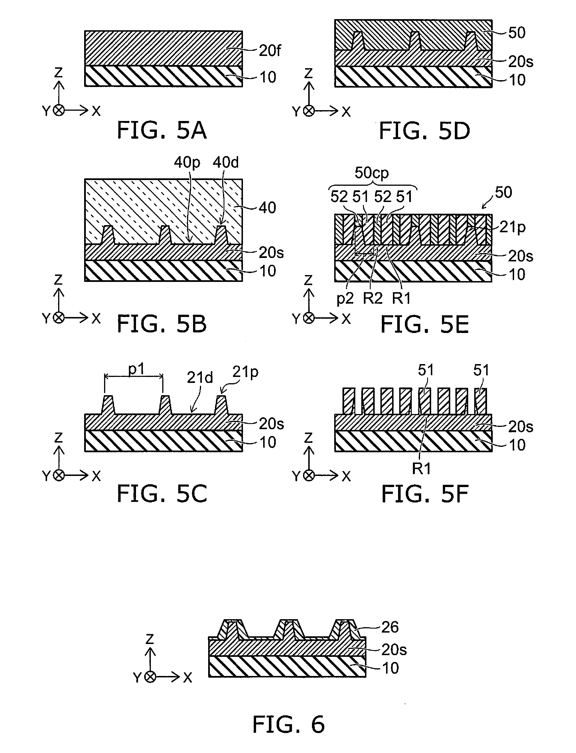
[0050] FIG. 4 is a flowchart illustrating the pattern formation method according to the second embodiment. FIG. 5A to FIG. 5F are schematic cross-sectional views illustrating the pattern formation method according to the second embodiment.
[0051] As shown in FIG. 4, before the first processing (step S110), a first film is formed at a structure body described below (step S101); and the second member 20 is formed (step S102). An example of step S101 and step S102 will now be described. In the following example, the second member 20 is formed by a method using a block copolymer. Also, a physical guide (a structure body) is used in the method using the block copolymer.
[0052] First, an example of the method for forming the structure body will be described. In the following example, the structure body is formed by imprinting.
[0053] As shown in FIG. 5A, a resin liquid film 20f is formed at the first member 10. A portion of the resin liquid film 20f is used to form the second member 20. The resin liquid film 20f has a liquid form. For example, the resin liquid film 20f is formed by coating.
[0054] As shown in FIG. 5B, a structure body 20s is obtained by causing a template 40 to contact the resin liquid film 20f. The surface of the template 40 includes a template protrusion 40p and a template recess 40d. The surface of the resin liquid film 20f conforms to the shape of the template protrusion 40p and the template recess 40d. The resin liquid film 20f is solidified in this state. For example, at least one of heating or irradiating light is performed. Thereby, the structure body 20s is obtained. Subsequently, the template 40 is released from the structure body 20s.
[0055] As shown in FIG. 5C, the structure body 20s includes a protrusion 21p and a recess 21d. The protrusion 21p corresponds to the template recess 40d. The recess 21d corresponds to the template protrusion 40p.
[0056] For example, multiple protrusions 21p are provided. The multiple protrusions 21p are arranged along the X-axis direction at a first pitch p1. For example, the multiple protrusions 21p have band configurations extending along the Y-axis direction.
[0057] An example of the method for obtaining the second member 20 using the structure body 20s and the block copolymer will now be described.
[0058] As shown in FIG. 5D, the structure body 20s is provided at the first member 10. The first film 50 is formed at the structure body 20s. For example, as shown in FIG. 5D, a liquid that is used to form the first film 50 is coated. For example, the coating is performed by spin coating, drop casting, or inkjet.
[0059] As shown in FIG. 5E, the first film 50 includes a block copolymer 50cp. The block copolymer 50cp includes multiple first portions 51 and multiple second portions 52. For example, after coating the first film 50 on the structure body 20s, phase separation of the first film 50 is caused by heating, etc. The phase separation is performed by self assembly. Thereby, the multiple first portions 51 and the multiple second portions 52 are arranged. At this time, the protrusions 21p of the structure body 20s function as a physical guide.
[0060] As shown in FIG. 5E, the structure body 20s includes multiple first regions R1 and multiple second regions R2. The regions that are positioned under the multiple first portions 51 are the first regions R1. The regions that are positioned under the multiple second portions 52 are the second regions R2. Thus, the multiple first regions R1 overlap the multiple first portions 51. The multiple second regions R2 overlap the multiple second portions 52.
[0061] For example, the multiple first portions 51 include styrene; and the multiple second portions 52 include a carbonyl group. For example, the multiple first portions 51 include polystyrene (PS). For example, the multiple second portions 52 include polymethyl methacrylate (PMMA).
[0062] For example, the multiple first portions 51 are arranged at a second pitch p2. The multiple second portions 52 are arranged at the second pitch p2. The multiple first regions R1 are arranged at the second pitch p2. The multiple second regions R2 are arranged at the second pitch p2. The second pitch p2 is smaller than the first pitch pl. The first pitch p1 is, for example, substantially an integer multiple of (an integer multiple not less than 2 times) the second pitch p2.
[0063] The multiple second portions 52 are removed as shown in FIG. 5F. For the etchant used in the removal, the etching rate of the etchant for the multiple first portions 51 is different from the etching rate of the etchant for the multiple second portions 52. The multiple second portions 52 are selectively removed by etching using such an etchant (e.g., a gas including oxygen). The multiple first portions 51 remain.
[0064] By continuing the etching further, the region of the structure body 20s not covered with the multiple first portions 51 is removed. As a result, the region (the multiple first regions R1) of the structure body 20s covered with the multiple first portions 51 remains. Thus, the second member 20 is obtained from the multiple first regions R1 (referring to FIG. 1A).
[0065] Thus, in the method recited above, the first film 50 is formed, before the first processing, at the structure body 20s provided at the first member 10 (step S101: referring to FIG. 4). The first film 50 includes the block copolymer 50cp including the multiple first portions 51 and the multiple second portions 52. The structure body 20s includes the multiple first regions R1 and the multiple second regions R2. The multiple first regions R1 overlap the multiple first portions 51. The multiple second regions R2 overlap the multiple second portions 52. Further, the second member 20 is obtained from the multiple first regions R1 by removing the multiple second portions 52 and the multiple second regions R2 (step S102: referring to FIG. 4).
[0066] In the embodiment, the structure body 20s includes, for example, at least one selected from the group consisting of an acrylic group, a ketone group, and an amino group.
[0067] The structure body 20s includes the multiple protrusions 21p. At least one of the multiple first regions R1 and at least one of the multiple second regions R2 are positioned between the multiple protrusions 21p (at the recess 21d). For example, a pair that includes one of the multiple first regions R1 and one of the multiple second regions R2 is positioned between the multiple protrusions 21p. Multiple pairs may be positioned between the multiple protrusions 21p.
[0068] For example, as shown in FIG. 5E, for example, at least one of the multiple second portions 52 overlaps one of the multiple protrusions 21p.
[0069] FIG. 6 is a schematic cross-sectional view illustrating a portion of the pattern formation method according to the second embodiment. As shown in FIG. 6, an intermediate film 26 may be formed at the structure body 20s. The formation of the intermediate film 26 is performed before the formation of the first film 50 (referring to FIG. 5A). The surface energy of the intermediate film 26 is between the surface energy of the multiple first portions 51 and the surface energy of the multiple second portions 52.
[0070] The formation of the intermediate film 26 includes, for example, performing neutralization processing of the surface of the structure body 20s. For example, the intermediate film 26 is formed at the surface of the structure body 20s by the neutralization processing.
[0071] For example, self assembly is performed more reliably due to the intermediate film 26. For example, the thickness of the intermediate film 26 on the protrusions 21p of the structure body 20s may be thinner than the thickness of the intermediate film 26 on the recesses 21d of the structure body 20s.
[0072] The embodiments may include the following configurations (e.g., technological proposals).
Configuration 1
[0073] A pattern formation method, comprising:
[0074] performing a first processing of causing a surface of a first member of a processing body to be hydrophobic, the processing body including the first member and a second member, the second member being provided at a portion of the first member;
[0075] performing a second processing of causing the processing body to contact an atmosphere including a metal compound, the second processing being after the first processing;
[0076] performing a third processing of processing the processing body in an atmosphere including at least one selected from the group consisting of water, oxygen, and ozone, the third processing being after the second processing; and
[0077] removing, after the third processing, at least a portion of another portion of the first member by using the second member as a mask.
Configuration 2
[0078] A pattern formation method, comprising:
[0079] performing a first processing of a processing body by using a compound including fluorine, the processing body including a first member and a second member, the second member being provided at a portion of the first member;
[0080] performing a second processing of causing the processing body to contact an atmosphere including a metal compound, the second processing being after the first processing;
[0081] performing a third processing of performing processing in an atmosphere including at least one selected from the group consisting of water, oxygen, and ozone, the third processing being after the second processing; and
[0082] removing, after the third processing, at least a portion of another portion of the first member by using the second member as a mask.
Configuration 3
[0083] The pattern formation method according to Configuration 2, wherein the compound including the fluorine includes an alkoxysilane compound including at least one of fluorine, an aromatic group, a cyclic hydrocarbon group, or an alkyl group.
Configuration 4
[0084] The pattern formation method according to Configuration 2, wherein the compound including the fluorocarbon.
Configuration 5
[0085] The pattern formation method according to Configuration 2, wherein the compound including the fluorine includes CF.sub.4.
Configuration 6
[0086] The pattern formation method according to Configuration 2, wherein the compound including the fluorine includes a polymer including fluorine.
Configuration 7
[0087] A pattern formation method, comprising:
[0088] performing a first processing of a processing body by using a compound including at least one selected from the group consisting of alkyldisilazane, and alkylchlorosilane, the processing body including a first member and a second member, the second member being provided at a portion of the first member;
[0089] performing a second processing of causing the processing body to contact an atmosphere including a metal compound, the second processing being after the first processing;
[0090] performing a third processing of performing processing in an atmosphere including at least one selected from the group consisting of water, oxygen, and ozone, the third processing being after the second processing; and
[0091] removing, after the third processing, at least a portion of another portion of the first member by using the second member as a mask.
Configuration 8
[0092] The pattern formation method according to Configuration 7, wherein the alkyldisilazane includes hexamethyldisilazan.
Configuration 9
[0093] The pattern formation method according to Configuration 7, wherein the alkyldisilazane includes at least one selected from the group consisting of octyltrichlorosilane, octadecyltrichlorosilane, and .beta.-phenethyltrichrolosilan.
Configuration 10
[0094] The pattern formation method according to any one of Configurations 1 to 9, wherein the second processing includes introducing the metallic element to the second member.
Configuration 11
[0095] The pattern formation method according to any one of Configurations 1 to 10, wherein the second processing includes causing the processing body to contact including the organo metal or metal chloride.
Configuration 12
[0096] The pattern formation method according to any one of Configurations 1 to 9, wherein the metal compound includes a metal complex including the metallic element.
Configuration 13
[0097] The pattern formation method according to any one of Configurations 1 to 9, wherein the metal compound includes trimethyl aluminum.
Configuration 14
[0098] The pattern formation method according to any one of Configurations 11, wherein the at least one of organo metal or metal chloride includes at least one selected from the group consisting of Ti, V, and W.
Configuration 15
[0099] The pattern formation method according to any one of Configurations 1 to 14, wherein the second member after the third processing includes an oxide including the metallic element.
Configuration 16
[0100] The pattern formation method according to any one of Configurations 1 to 15, wherein the removing includes causing the other portion of the first member to contact a gas including at least one selected from the group consisting of fluorine, chlorine, and carbon.
Configuration 17
[0101] The pattern formation method according to any one of Configurations 1 to 16, wherein
[0102] the first member includes at least one selected from the group consisting of silicon oxide, silicon nitride, silicon oxynitride, aluminum oxide, aluminum nitride, aluminum oxynitride, silicon, aluminum, and a compound semiconductor, and
[0103] the second member includes a resin.
Configuration 18
[0104] The pattern formation method according to any one of Configurations 1 to 14, wherein the second member includes at least one selected from the group consisting of an acrylic group, a ketone group, and an amino group.
Configuration 19
[0105] The pattern formation method according to any one of Configurations 1 to 16, further comprising:
[0106] forming, before the first processing, a first film at a structure body provided at the first member, the first film including a block copolymer including multiple first portions and multiple second portions, the structure body including multiple first regions and multiple second regions, the multiple first regions overlapping the multiple first portions, the multiple second regions overlapping the multiple second portions; and
[0107] obtaining the second member from the multiple first regions by removing the multiple second portions and the multiple second regions.
Configuration 20
[0108] The pattern formation method according to Configuration 19, wherein
[0109] the multiple first portions include styrene, and
[0110] the multiple second portions include a carbonyl group.
Configuration 21
[0111] The pattern formation method according to Configuration 19 or 20, wherein the structure body includes at least one selected from the group consisting of an acrylic group, a ketone group, and an amino group.
Configuration 22
[0112] The pattern formation method according to any one of Configurations 19 to 21, wherein
[0113] the structure body includes multiple protrusions, and
[0114] at least one of the multiple first regions and at least one of the multiple second regions are positioned between the multiple protrusions.
Configuration 23
[0115] The pattern formation method according to Configuration 22, wherein at least one of the multiple second portions overlaps one of the multiple protrusions.
[0116] According to the embodiments, a pattern formation method can be provided in which the accuracy can be increased.
[0117] Hereinabove, exemplary embodiments of the invention are described with reference to specific examples. However, the embodiments of the invention are not limited to these specific examples. For example, one skilled in the art may similarly practice the invention by appropriately selecting specific configurations of first members, second members, structure bodies, first films, and block copolymers, etc., from known art. Such practice is included in the scope of the invention to the extent that similar effects thereto are obtained.
[0118] Further, any two or more components of the specific examples may be combined within the extent of technical feasibility and are included in the scope of the invention to the extent that the purport of the invention is included.
[0119] Moreover, all pattern formation methods practicable by an appropriate design modification by one skilled in the art based on the pattern formation methods described above as embodiments of the invention also are within the scope of the invention to the extent that the spirit of the invention is included.
[0120] Various other variations and modifications can be conceived by those skilled in the art within the spirit of the invention, and it is understood that such variations and modifications are also encompassed within the scope of the invention.
[0121] While certain embodiments have been described, these embodiments have been presented by way of example only, and are not intended to limit the scope of the inventions. Indeed, the novel embodiments described herein may be embodied in a variety of other forms; furthermore, various omissions, substitutions and changes in the form of the embodiments described herein may be made without departing from the spirit of the inventions. The accompanying claims and their equivalents are intended to cover such forms or modifications as would fall within the scope and spirit of the invention.
* * * * *
D00000
D00001
D00002
D00003
XML
uspto.report is an independent third-party trademark research tool that is not affiliated, endorsed, or sponsored by the United States Patent and Trademark Office (USPTO) or any other governmental organization. The information provided by uspto.report is based on publicly available data at the time of writing and is intended for informational purposes only.
While we strive to provide accurate and up-to-date information, we do not guarantee the accuracy, completeness, reliability, or suitability of the information displayed on this site. The use of this site is at your own risk. Any reliance you place on such information is therefore strictly at your own risk.
All official trademark data, including owner information, should be verified by visiting the official USPTO website at www.uspto.gov. This site is not intended to replace professional legal advice and should not be used as a substitute for consulting with a legal professional who is knowledgeable about trademark law.