Optical Imaging Lens Assembly
SONG; Bo ; et al.
U.S. patent application number 16/229724 was filed with the patent office on 2019-04-25 for optical imaging lens assembly. The applicant listed for this patent is Zhejiang Sunny Optical Co., Ltd. Invention is credited to Yabin HU, Bo SONG, Jianke WENREN, Kaiyuan ZHANG.
| Application Number | 20190121100 16/229724 |
| Document ID | / |
| Family ID | 65722366 |
| Filed Date | 2019-04-25 |


View All Diagrams
| United States Patent Application | 20190121100 |
| Kind Code | A1 |
| SONG; Bo ; et al. | April 25, 2019 |
OPTICAL IMAGING LENS ASSEMBLY
Abstract
An optical imaging lens assembly is provided. The optical imaging lens assembly includes, sequentially along an optical axis from an object side to an image side, a first lens, a second lens, a third lens, a fourth lens, a fifth lens, a sixth lens, and a seventh lens. The first lens has a positive refractive power, the second lens and the seventh lens have a negative refractive power, and the third, fourth, fifth, and sixth lenses have a positive refractive power or a negative refractive power. Object-side surfaces of the first lens and the second lens are a convex surface, object-side surfaces of the fourth lens and the seventh lens are a concave surface, and image-side surfaces of the first, second, and seventh lens are a concave surface. A total effective focal length f and an entrance pupil diameter EPD of the optical imaging lens assembly satisfy: f/EPD.ltoreq.1.70.
| Inventors: | SONG; Bo; (Ningbo City, CN) ; WENREN; Jianke; (Ningbo City, CN) ; ZHANG; Kaiyuan; (Ningbo City, CN) ; HU; Yabin; (Ningbo City, CN) | ||||||||||
| Applicant: |
|
||||||||||
|---|---|---|---|---|---|---|---|---|---|---|---|
| Family ID: | 65722366 | ||||||||||
| Appl. No.: | 16/229724 | ||||||||||
| Filed: | December 21, 2018 |
Related U.S. Patent Documents
| Application Number | Filing Date | Patent Number | ||
|---|---|---|---|---|
| PCT/CN2018/088686 | May 28, 2018 | |||
| 16229724 | ||||
| Current U.S. Class: | 1/1 |
| Current CPC Class: | G02B 9/64 20130101; G02B 13/00 20130101; G02B 13/0045 20130101 |
| International Class: | G02B 13/00 20060101 G02B013/00; G02B 9/64 20060101 G02B009/64 |
Foreign Application Data
| Date | Code | Application Number |
|---|---|---|
| Sep 13, 2017 | CN | 201710820209.6 |
| Sep 13, 2017 | CN | 201721167337.7 |
Claims
1. An optical imaging lens assembly comprising, sequentially along an optical axis from an object side to an image side, a first lens, a second lens, a third lens, a fourth lens, a fifth lens, a sixth lens, and a seventh lens, wherein the first lens has a positive refractive power, an object-side surface of the first lens is a convex surface, and an image-side surface of the first lens is a concave surface; the second lens has a negative refractive power, an object-side surface of the second lens is a convex surface, and an image-side surface of the second lens a concave surface; the third lens has a positive refractive power or a negative refractive power; the fourth lens has a positive refractive power or a negative refractive power, and an object-side surface of the fourth lens is a concave surface; the fifth lens has a positive refractive power or a negative refractive power; the sixth lens has a positive refractive power or a negative refractive power; the seventh lens has a negative refractive power, an object-side surface of the seventh lens is a concave surface, and an image-side surface of the seventh lens is a concave surface; and a total effective focal length f of the optical imaging lens assembly and an entrance pupil diameter EPD of the optical imaging lens assembly satisfy: f/EPD.ltoreq.1.70.
2. The optical imaging lens assembly according to claim 1, wherein an effective focal length f2 of the second lens and an effective focal length f7 of the seventh lens satisfy: 2.8<f2/f7<7.0.
3. The optical imaging lens assembly according to claim 1, wherein the total effective focal length f of the optical imaging lens assembly and an effective focal Length f5 of the fifth lens satisfy: |f/f5|.ltoreq.1.0.
4. The optical imaging lens assembly according to claim 1, wherein the total effective focal length f of the optical imaging lens assembly and an effective focal length f6 of the sixth lens satisfy: -0.5<f/f6<1.5.
5. The optical imaging lens assembly according to claim 1, wherein a radius of curvature R3 of the object-side surface of the second lens and a radius of curvature R4 of the image-side surface of the second lens satisfy: 2<R3/R4<5.
6. The optical imaging lens assembly according to claim 1, wherein a radius of curvature R11 of an object-side surface of the sixth lens and a radius of curvature R12 of an image-side surface of the sixth lens satisfy: -10<R11/R12<5.
7. The optical imaging lens assembly according to claim 1, wherein the optical imaging lens assembly further comprises a diaphragm disposed between the second lens and the third lens.
8. The optical imaging lens assembly according to claim 1, wherein an axial distance TTL from the object-side surface of the first lens to an image plane of the optical imaging lens assembly and half of a diagonal length ImgH of an effective pixel area on the image plane satisfy: TTL/ImgH<1.6.
9. The optical imaging lens assembly according to claim 1, wherein a maximum field-of-view FOV of the optical imaging lens assembly satisfies: 70.degree.<FOV<80.degree..
10. The optical imaging lens assembly according to claim 1, wherein an axial distance TTL from the object-side surface of the first lens to an image plane of the optical imaging lens assembly and the total effective focal length f of the optical imaging lens assembly satisfy: 1.0<TTL/f<2.0.
11. An optical imaging lens assembly comprising, sequentially along an optical axis from an object side to an image side, a first lens, a second lens, a third lens, a fourth lens, a fifth lens, a sixth lens, and a seventh lens, wherein each of the first lens and the third. lens has a positive refractive power; at least one of the second lens or the seventh lens has a negative refractive power; each of the fourth lens, the fifth lens, and the sixth lens has a positive refractive power or a negative refractive power; an object-side surface of the first lens is a convex surface, and an image-side surface of the first lens is a concave surface; an object-side surface of the fourth lens is a concave surface; an object-side surface of the fifth lens is a convex surface; an object-side surface and an image-side surface of the seventh lens are concave surfaces; and half of a diagonal length ImgH of an effective pixel area on an image plane of the optical imaging lens assembly, a total effective focal length f of the optical imaging lens assembly, and an entrance pupil diameter EPD of the optical imaging lens assembly satisfy: 1 mm<ImgH/(f/EPD)<3 mm.
12. The optical imaging lens assembly according to claim 11, wherein an effective focal length f2 of the second lens and an effective focal length f7 of the seventh lens satisfy: 2.8<f2/f7<7.0.
13. The optical imaging lens assembly according to claim 11, wherein the total effective focal length f of the optical imaging lens assembly and an effective focal length f5 of the fifth lens satisfy: |f/f5|.ltoreq.1.0.
14. The optical imaging lens assembly according to claim 11, wherein the total effective focal length f of the optical imaging lens assembly and an effective focal length f6 of the sixth lens satisfy: -0.5<f/f6<1.5.
15. The optical imaging lens assembly according to claim 11, wherein an object-side surface of the second lens is a convex surface, and an image-side surface of the second lens is a concave surface, and a radius of curvature R3 of the object-side surface of the second lens and a radius of curvature R4 of the image-side surface of the second lens satisfy: 2<R3/R4<5.
16. The optical imaging lens assembly according to claim 11, wherein the optical imaging lens assembly further comprises a diaphragm disposed between the second lens and the third lens.
17. The optical imaging lens assembly according to claim 16, wherein a spacing distance T56 on the optical axis between the fifth lens and the sixth lens and a spacing distance T67 on the optical axis between the sixth lens and the seventh lens satisfy: 0<T56/T67<5.
18. The optical imaging lens assembly according to claim 16, wherein the optical imaging lens assembly satisfies 1.5<(T23+T34+T45)/(T56+T67)<3.0, T23 is a spacing distance on the optical axis between the second lens and the third lens; T34 is a spacing distance on the optical axis between the third lens and the fourth lens; T45 is a spacing distance on the optical axis between the fourth lens and the fifth lens; T56 is a spacing distance on the optical axis between the fifth lens and the sixth lens; and T67 is a spacing distance on the optical axis between the sixth lens and the seventh lens.
19. The optical imaging lens assembly according to claim 17, wherein an axial distance TTL from the object-side surface of the first lens to the image plane of the optical imaging lens assembly and the total effective focal length f of the optical imaging lens assembly satisfy: 1.0<TTL/f<2.0.
20. The optical imaging lens assembly according to claim 17, wherein an axial distance TTL from the object-side surface of the first lens to the image plane of the optical imaging lens assembly and the half of the diagonal length ImgH of the effective pixel area on the image plane satisfy: TTL/ImgH<1.6.
Description
CROSS-REFERENCE TO RELATED APPLICATIONS
[0001] This disclosure is a continuation of International Application PCT/CN2018/088686, with an international filing date of May 28, 2018, which claims priority to Chinese Patent Application no. 201710820209.6, filed with the China National Intellectual Property Administration (CNIPA) on Sep. 13, 2017, and Chinese Patent Application no. 201721167337.7, filed with the China National Intellectual Property Administration (CNIPA) on Sep. 13, 2017, the contents of which are incorporated herein by reference in their entirety.
TECHNICAL FIELD
[0002] The present disclosure relates to an optical imaging lens assembly, and more specifically to an ultra-thin optical imaging lens assembly including seven lenses and having a large aperture.
BACKGROUND
[0003] With the development of science and technology, portable electronic products are gradually increasing, and portable electronic products having camera functions are increasingly favored by the consumers. Therefore, there is an increasing demand for camera lens assemblies suitable for the portable electronic products. The tendency of miniaturization of the portable electronic products would limit the total length of a lens assembly, thereby increasing the difficulty in designing the lens assembly.
[0004] Meanwhile, with the improvement in performance and reduction in size of the commonly used photosensitive elements such as charge-coupled devices (CCD) or complementary metal-oxide semiconductor elements (CMOS), the number of pixels on the photosensitive elements is increased and the size of the pixels is reduced. Accordingly, higher requirements on high imaging quality and miniaturization of the counterpart optical imaging lens assemblies have been brought forward.
[0005] The reduction of the size of the pixels implies that the light flux of the lens assembly would be reduced in the same exposure time. However, the image sensor, the environment background and so on have some system noises, and thus there are strong needs for the light flux of the optical imaging lens assembly. At this time, the larger the effective amount of light entering the optical imaging lens assembly is, the better the imaging performance of the optical imaging lens assembly is.
[0006] Therefore, it is necessary to provide an optical imaging lens assembly that may be suitable for the portable electronic products and have an ultra-thin large aperture and a good imaging quality.
SUMMARY
[0007] The present disclosure provides an imaging lens assembly which may be applicable to portable electronic products and may at least or partially solve at least one of the above disadvantages in the existing technology, for example, an ultra-thin lens assembly having a large aperture.
[0008] According to an aspect, the present disclosure provides an optical imaging lens assembly. The optical imaging lens assembly includes, sequentially along an optical axis from an object side to an image side, a first lens, a second lens, a third lens, a fourth lens, a fifth lens, a sixth lens, and a seventh lens. The first lens may have a positive refractive power, an object-side surface of the first lens may be a convex surface, and an image-side surface of the first lens may be a concave surface. The second lens may have a negative refractive power, an object-side surface of the second lens may be a convex surface, and an image-side surface of the second lens may be a concave surface. The third lens may have a positive refractive power or a negative refractive power. The fourth lens may have a positive refractive power or a negative refractive power, and an object-side surface of the fourth lens may be a concave surface. The fifth lens may have a positive refractive power or a negative refractive power. The sixth lens may have a positive refractive power or a negative refractive power. The seventh lens may have a negative refractive power, an object-side surface of the seventh lens may be a concave surface, and an image-side surface of the seventh lens may be a concave surface. A total effective focal length f of the optical imaging lens assembly and an entrance pupil diameter EPD of the optical imaging lens assembly may satisfy: f/EPD.ltoreq.1.70.
[0009] In an implementation, the total effective focal length f of the optical imaging lens assembly and an effective focal length f5 of the fifth lens may satisfy: |f/f5|.ltoreq.1.0.
[0010] In an implementation, the total effective focal length f of the optical imaging lens assembly and an effective focal length f6 of the sixth lens may satisfy: -0.5<f/f6<1.5.
[0011] In an implementation, a spacing distance T23 on the optical axis between the second lens and the third lens, a spacing distance T34 on the optical axis between the third lens and the fourth lens, a spacing distance T45 on the optical axis between the fourth lens and the fifth lens, a spacing distance T56 on the optical axis between the fifth lens and the sixth lens, and a spacing distance T67 on the optical axis between the sixth lens and the seventh lens may satisfy: 0<(T23+T34+T45)/(T56+T67)<3.0.
[0012] In an implementation, the spacing distance T23 on the optical axis between the second lens and the third lens, the spacing distance T34 on the optical axis between the third lens and the fourth lens, the spacing distance T45 on the optical axis between the fourth lens and the fifth lens, the spacing distance T56 on the optical axis between the fifth lens and the sixth lens, and the spacing distance T67 on the optical axis between. the sixth lens and the seventh lens may satisfy:
1.5<(T23+T34+T45)/(T56+T67)<3.0.
[0013] In an implementation, the spacing distance T56 on the optical axis between the fifth lens and the sixth lens and the spacing distance T67 on the optical axis between the sixth lens and the seventh lens may satisfy:
0<T56/T67<5.
[0014] In an implementation, a radius of curvature R3 of the object-side surface of the second lens and a radius of curvature R4 of the image-side surface of the second lens may satisfy: 2<R3/R4<5.
[0015] In an implementation, a radius of curvature R11 of an object-side surface of the sixth lens and a radius of curvature R12 of an image-side surface of the sixth lens may satisfy: -10<R11/R12<5.
[0016] In an implementation, the optical imaging lens assembly may further include a diaphragm disposed between the second lens and the third lens.
[0017] In an implementation, an axial distance TTL from the object-side surface of the first lens to an image plane of the optical imaging lens assembly and half of a diagonal length ImgH of an effective pixel area on the image plane may satisfy: TTL/ImgH<1.6.
[0018] In an implementation, a maximum field-of-view FOV of the optical imaging lens assembly may satisfy: 70.degree.<FOV<80.degree.
[0019] In an implementation, the axial distance TTL from the object-side surface of the first lens to the image plane of the optical imaging lens assembly and the total effective focal length f of the optical imaging lens assembly may satisfy: 1.0<TTL/f<2.0.
[0020] In an implementation, the half of the diagonal length ImgH of the effective pixel area on the image plane, the total effective focal length f of the optical imaging lens assembly, and the entrance pupil diameter EPD of the optical imaging lens assembly may satisfy: 1 mm<ImgH/(f/EPD)<3 mm.
[0021] According to another aspect, the present disclosure further provides an optical imaging lens assembly. The optical imaging lens assembly includes, sequentially along an optical axis from an object side to an image side, a first lens, a second lens, a third lens, a fourth lens, a fifth lens, a sixth lens, and a seventh lens. Each of the first lens and the third lens may have a positive refractive power. At least one of the second lens or the seventh lens may have a negative refractive power. Each of the fourth lens, the fifth lens, and the sixth lens may have a positive refractive power or a negative refractive power. An object-side surface of the first lens may be a convex surface, and an image-side surface of the first lens may be a concave surface. An object-side surface of the fourth lens may be a concave surface. An object-side surface of the fifth lens may be a convex surface. An object-side surface and an image-side surface of the seventh lens may both be concave surfaces. Half of a diagonal length ImgH of an effective pixel area on an image plane of the optical imaging lens assembly, a total effective focal length f of the optical imaging lens assembly, and an entrance pupil diameter EPD of the optical imaging lens assembly may satisfy: 1 mm<ImgH/(f/EPD)<3 mm.
[0022] In an implementation, each of the second lens and the seventh lens may have a negative refractive power.
[0023] According to another aspect, the present disclosure provides an optical imaging lens assembly. The optical imaging lens assembly includes, sequentially along an optical axis from an object side to an image side, a first lens, a second lens, a third lens, a fourth lens, a fifth lens, a sixth lens, and a seventh lens. The first lens may have a positive refractive power, an object-side surface of the first lens may be a convex surface, and an image-side surface of the first lens may be a concave surface. The second lens may have a negative refractive power, an object-side surface of the second lens may be a convex surface, and an image-side surface of the second lens may be a concave surface. The third lens may have a positive refractive power or a negative refractive power. The fourth lens may have a positive refractive power or a negative refractive power, and an object-side surface of the fourth lens may be a concave surface. The fifth lens may have a positive refractive power or a negative refractive power. The sixth lens may have a positive refractive power or a negative refractive power. The seventh lens may have a negative refractive power, an object-side surface of the seventh lens may be a concave surface, and an image-side surface of the seventh lens may be a concave surface. A radius of curvature R3 of the object-side surface of the second lens and a radius of curvature R4 of the image-side surface of the second lens may satisfy: 2<R3/R4<5.
[0024] The present disclose adopts a plurality of lenses, for example, seven lenses. By reasonably distributing the refractive powers and the surface types of the lenses, the center thicknesses of the lenses, the spacing distances on the optical axis between the lenses, etc., the system has advantages of the large aperture in the process of increasing the amount of the light admitted, thus improving the imaging effect of the optical imaging lens assembly. Meanwhile, the lens assembly with the above configuration may have at least one of the beneficial effects of ultra-thin, miniaturization, large-aperture, or high imaging quality.
BRIEF DESCRIPTION OF THE DRAWINGS
[0025] By describing non-limiting implementations below in detail with reference to the accompanying drawings, other features, objectives and advantages of the present disclosure will be more apparent. In the accompanying drawings:
[0026] FIG. 1 is a schematic structural diagram illustrating an optical imaging lens assembly according to Embodiment 1 of the present disclosure;
[0027] FIGS. 2A-2D respectively illustrate a longitudinal aberration curve, an astigmatic curve, a distortion curve, and a lateral color curve of the optical imaging lens assembly according to Embodiment 1;
[0028] FIG. 3 is a schematic structural diagram illustrating an optical imaging lens assembly according to Embodiment 2 of the present disclosure;
[0029] FIGS. 4A-4D respectively illustrate a longitudinal aberration curve, an astigmatic curve, a distortion curve, and a lateral color curve of the optical imaging lens assembly according to Embodiment 2;
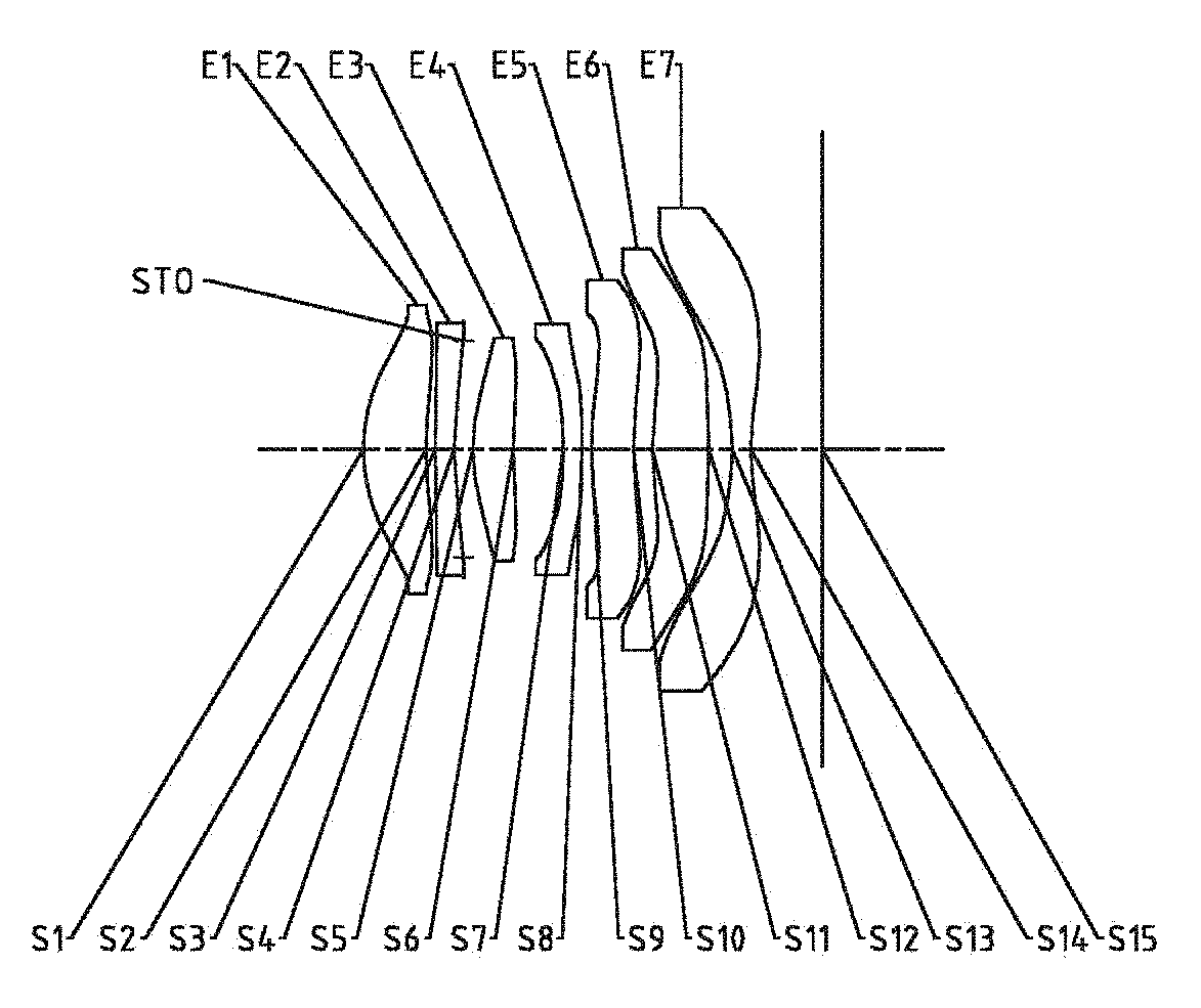
[0030] FIG. 5 is a schematic structural diagram illustrating an optical imaging lens assembly according to Embodiment 3 of the present disclosure;
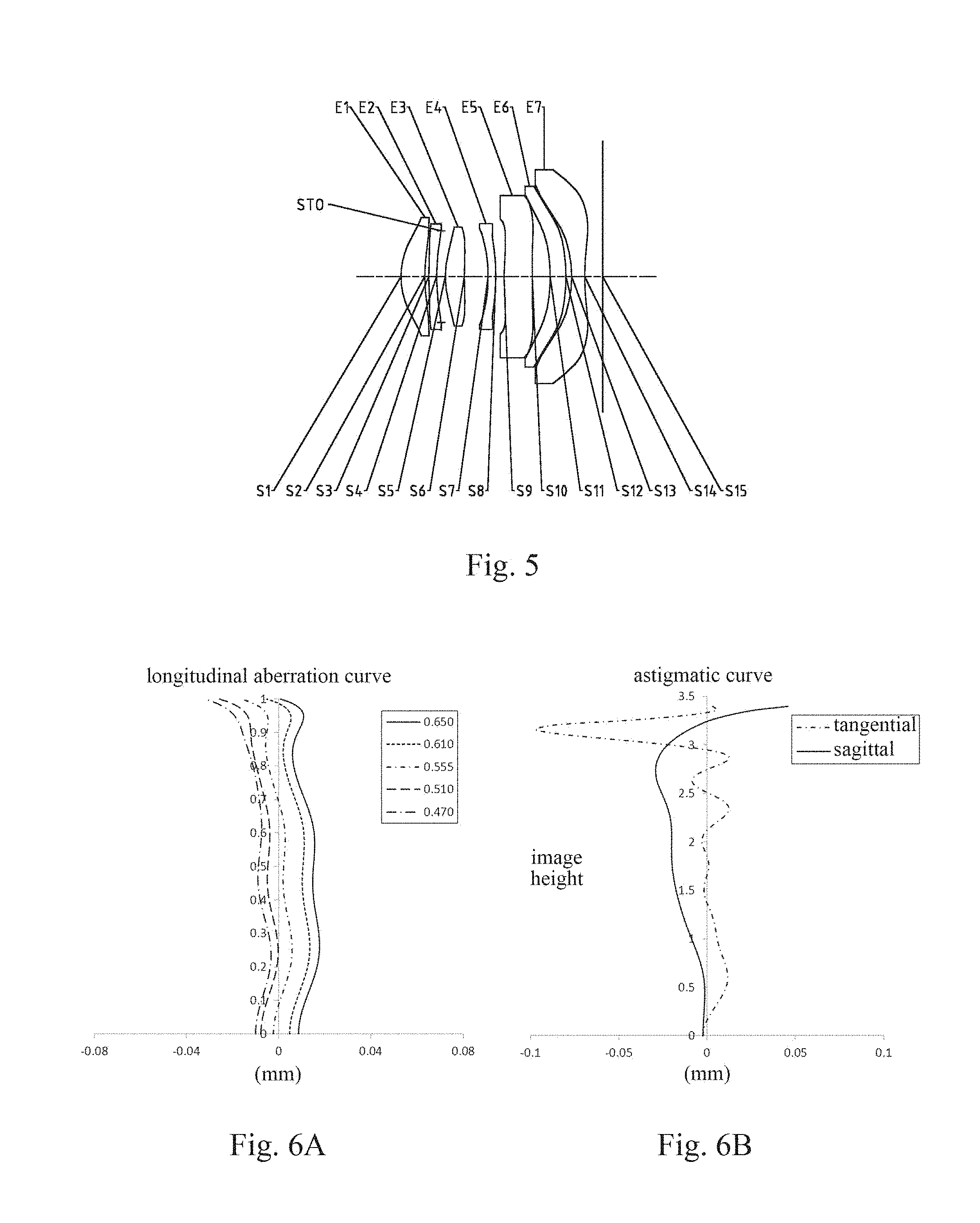
[0031] FIGS. 6A-6D respectively illustrate a longitudinal aberration curve, an astigmatic curve, a distortion curve, and a lateral color curve of the optical imaging lens assembly according to Embodiment 3;
[0032] FIG. 7 is a schematic structural diagram illustrating an optical imaging lens assembly according to Embodiment 4 of the present disclosure;
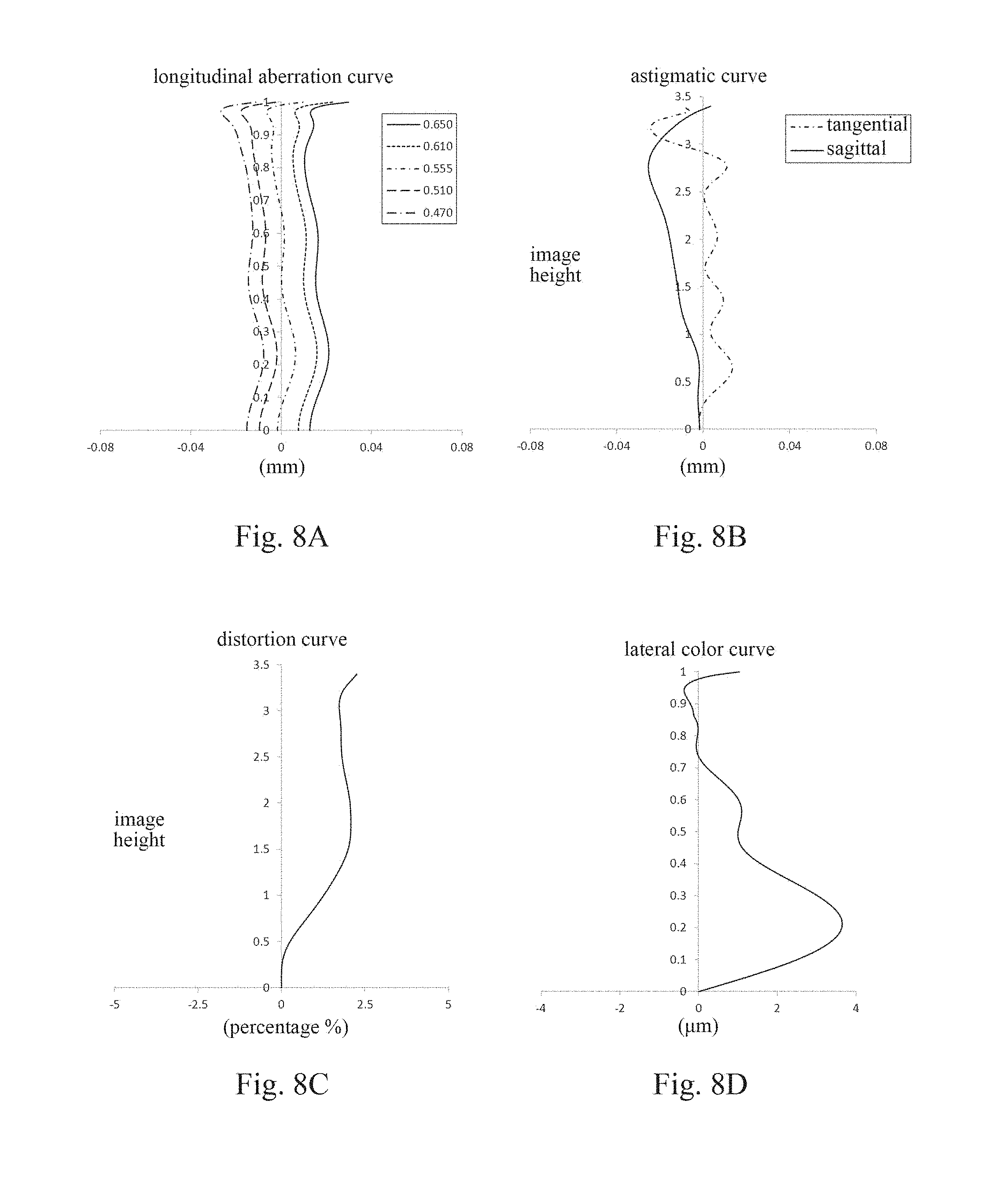
[0033] FIGS. 8A-8D respectively illustrate a longitudinal aberration curve, an astigmatic curve, a distortion curve, and a lateral color curve of the optical imaging lens assembly according to Embodiment 4;
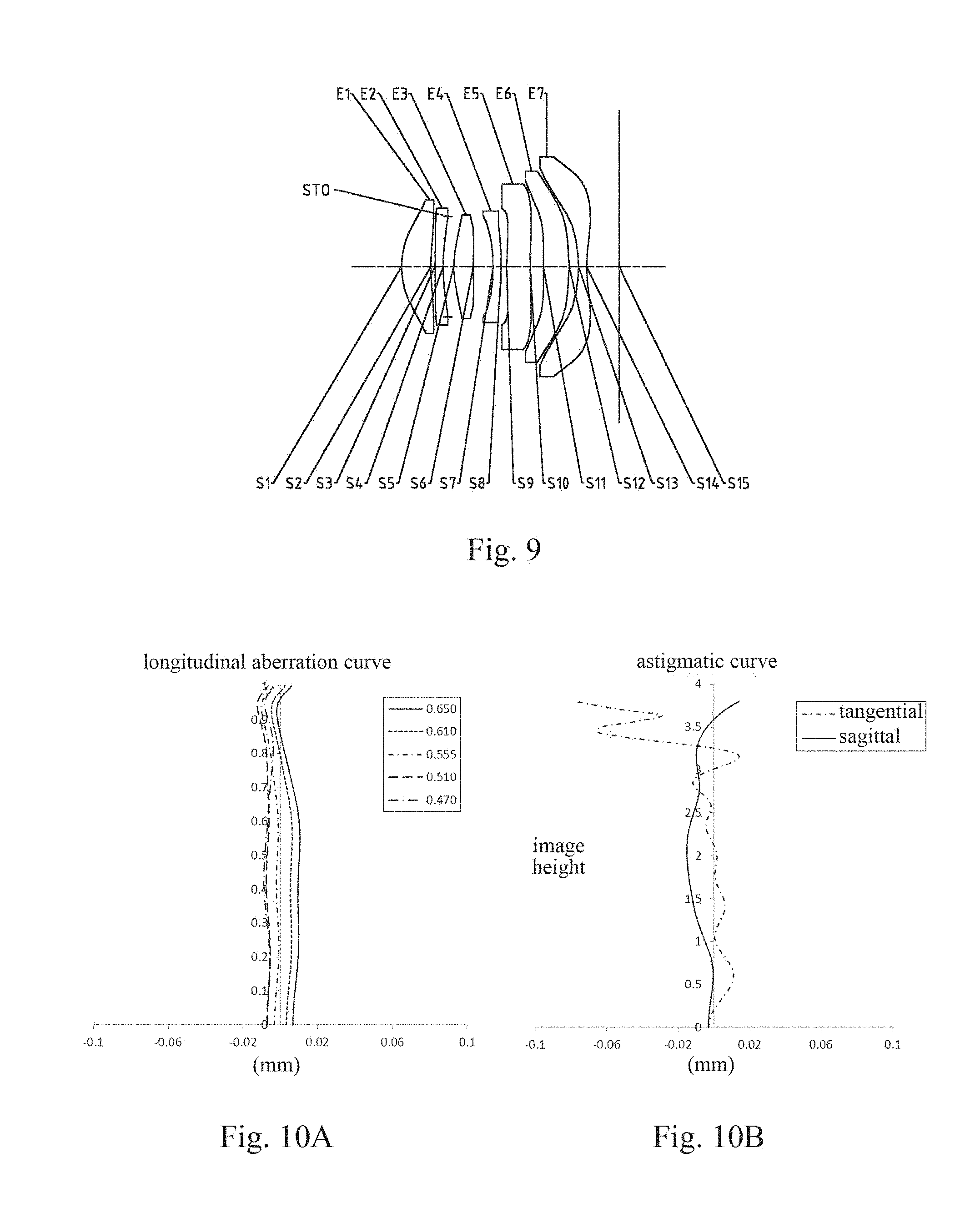
[0034] FIG. 9 is a schematic structural diagram illustrating an optical imaging lens assembly according to Embodiment 5 of the present disclosure;
[0035] FIGS. 10A-10D respectively illustrate a longitudinal aberration curve, an astigmatic curve, a distortion curve, and a lateral color curve of the optical imaging lens assembly according to Embodiment 5;
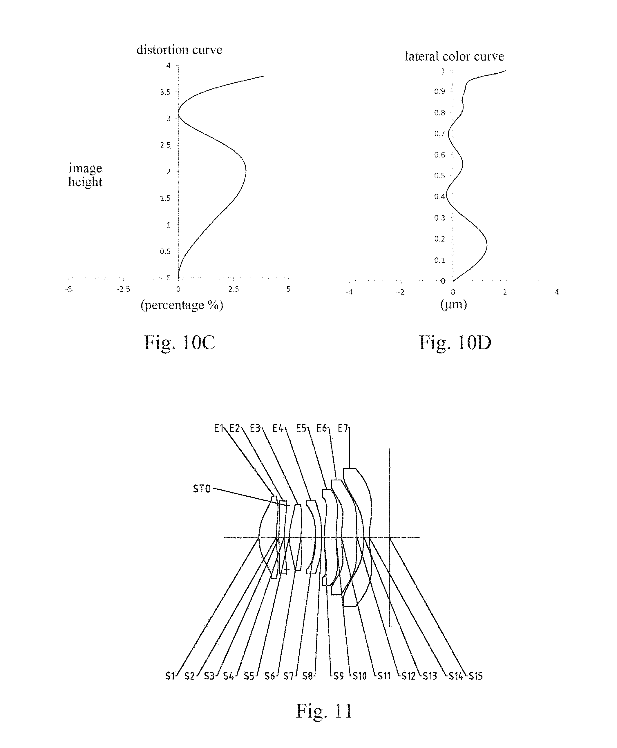
[0036] FIG. 11 is a schematic structural diagram illustrating an optical imaging lens assembly according to Embodiment 6 of the present disclosure;
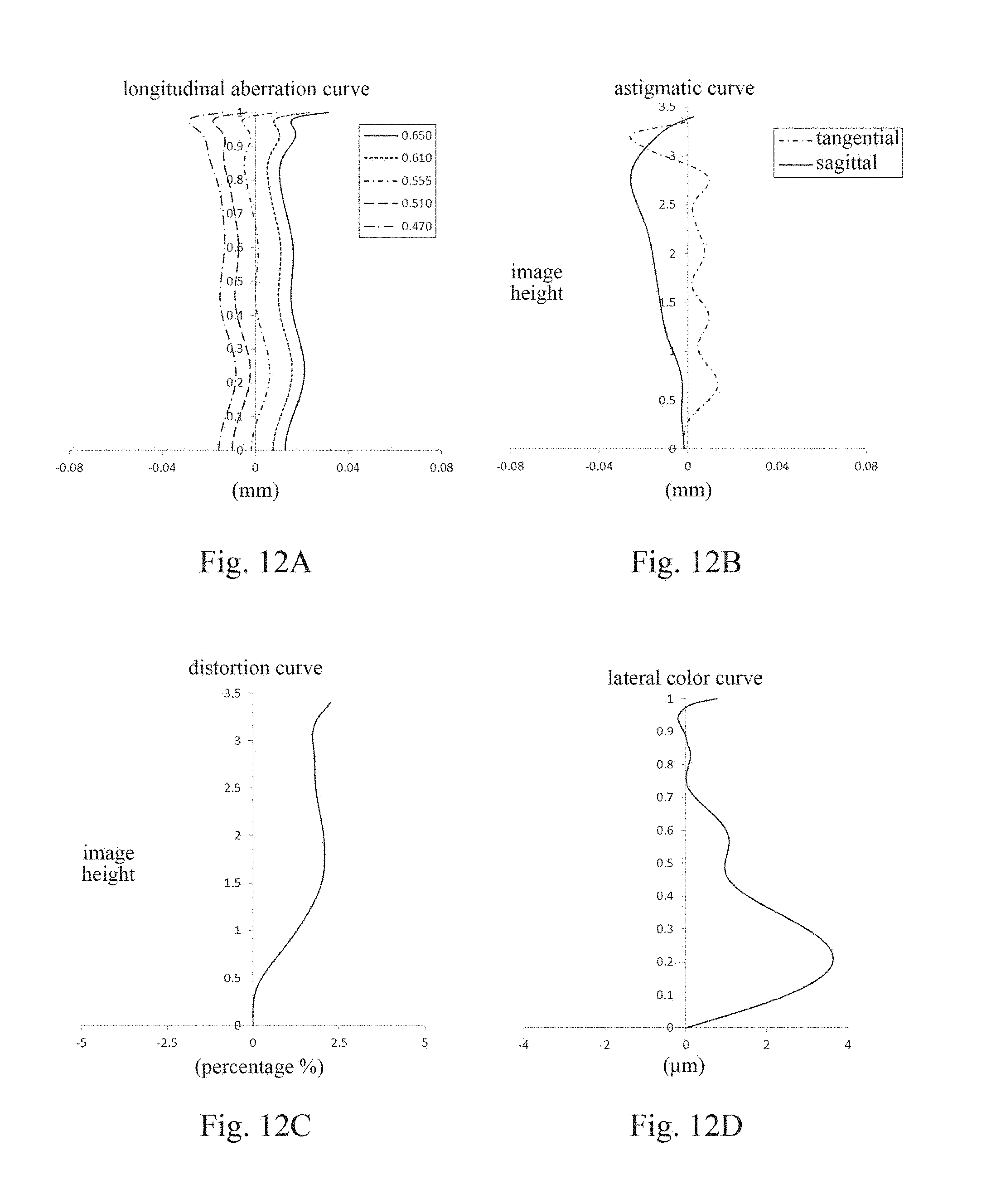
[0037] FIGS. 12A-12D respectively illustrate a longitudinal aberration curve, an astigmatic curve, a distortion curve, and a lateral color curve of the optical imaging lens assembly according to Embodiment 6;
[0038] FIG. 13 is a schematic structural diagram illustrating an optical imaging lens assembly according to Embodiment 7 of the present disclosure;
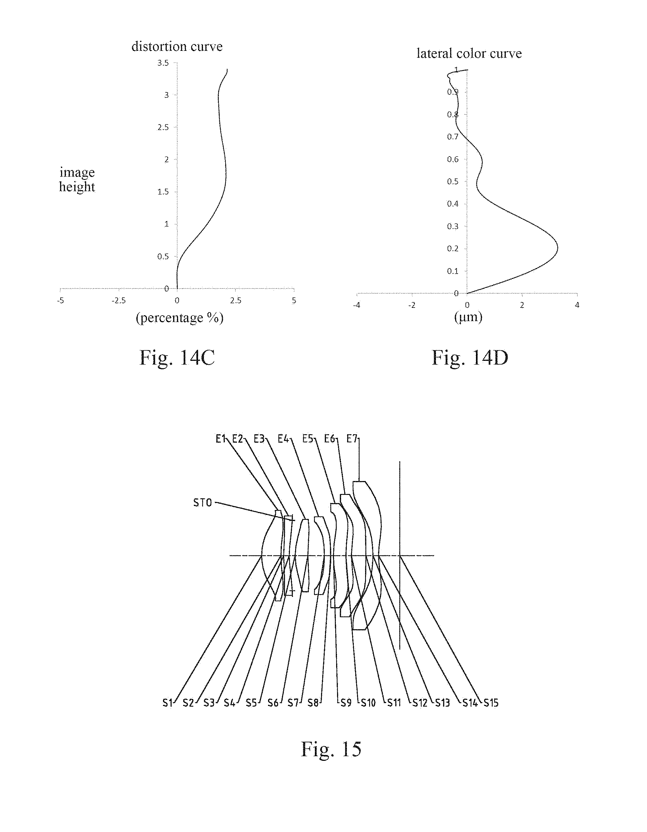
[0039] FIGS. 14A-14D respectively illustrate a longitudinal aberration curve, an astigmatic curve, a distortion curve, and a lateral color curve of the optical imaging lens assembly according to Embodiment 7;
[0040] FIG. 15 is a schematic structural diagram illustrating an optical imaging lens assembly according to Embodiment 8 of the present disclosure; and
[0041] FIGS. 16A-16D respectively illustrate a longitudinal aberration curve, an astigmatic curve, a distortion curve, and a lateral color curve of the optical imaging lens assembly according to Embodiment 8.
[0042] FIG. 17 is a schematic structural diagram illustrating an optical imaging lens assembly according to Embodiment 9 of the present disclosure; and
[0043] FIGS. 18A-18D respectively illustrate a longitudinal aberration curve, an astigmatic curve, a distortion curve, and a lateral color curve of the optical imaging lens assembly according to Embodiment 9.
DETAILED DESCRIPTION
[0044] For a better understanding of the present disclosure, various aspects of the present disclosure will be described in more detail with reference to the accompanying drawings. It should be understood that the detailed description is merely an illustration for the exemplary implementations of the present disclosure rather than a limitation to the scope of the present disclosure in any way. Throughout the specification, the same reference numerals designate the same elements. The expression "and/or" includes any and all combinations of one or more of the associated listed items.
[0045] It should be noted that in the specification, the expressions, such as "first," "second," and "third" are only used to distinguish one feature from another, rather than represent any limitations to the features. Thus, the first lens discussed below may also be referred to as the second lens or the third lens without departing from the teachings of the present disclosure.
[0046] In the accompanying drawings, the thicknesses, sizes and shapes of the lenses have been slightly exaggerated for the convenience of explanation. Specifically, shapes of spherical surfaces or aspheric surfaces shown in the accompanying drawings are shown by examples. That is, the shapes of the spherical surfaces or the aspheric surfaces are not limited to the shapes of the spherical surfaces or the aspheric surfaces shown in the accompanying drawings. The accompanying drawings are merely illustrative and not strictly drawn to scale.
[0047] Herein, the paraxial area refers to an area near the optical axis. If a surface of a lens is a convex surface and a position of the convex surface is not defined, it indicates that the surface of the lens is a convex surface at least in the paraxial area; and if a surface of a lens is a concave surface and a position of the concave surface is not defined, it indicates that the surface of the lens is a concave surface at least in the paraxial area. The surface closest to the object in each lens is referred to as the object-side surface, and the surface closest to the image plane in each lens is referred to as the image-side surface.
[0048] It should be further understood that the terms "comprising," "including," "having" and variants thereof, when used in the specification, specify the presence of stated features, elements and/or components, but do not exclude the presence or addition of one or more other features, elements, components and/or combinations thereof. In addition, expressions, such as "at least one of," when preceding a list of listed features, modify the entire list of features rather than an individual element in the list. Further, the use of "may," when describing the implementations of the present disclosure, relates to "one or more implementations of the present disclosure." Also, the term "exemplary" is intended to refer to an example or illustration.
[0049] Unless otherwise defined, all terms (including technical and scientific terms) used herein have the same meaning as commonly understood by those of ordinary skill in the art to which the present disclosure belongs. It should be further understood that terms (i.e., those defined in commonly used dictionaries) should be interpreted as having a meaning that is consistent with their meaning in the context of the relevant art and will not be interpreted in an idealized or overly formal sense unless expressly so defined herein.
[0050] It should also be noted that the embodiments in the present disclosure and the features in the embodiments may be combined with each other on a non-conflict basis. The present disclosure will be described below in detail with reference to the accompanying drawings and in combination with the embodiments.
[0051] Features, principles, and other aspects of the present disclosure are described below in detail.
[0052] The optical imaging lens assembly according to exemplary implementations of the present disclosure includes, for example, seven lenses (i.e., a first lens, a second lens, a third lens, a fourth lens, a fifth lens, a sixth lens, and a seventh lens). The seven lenses are arranged in sequence along an optical axis from an object side to an image side. The optical imaging lens assembly may further include a photosensitive element disposed on an image plane.
[0053] The first lens may have a positive refractive power, the object-side surface of the first lens may be a convex surface, and the image-side surface of the first lens may be a concave surface. The second lens may have a negative refractive power, and the third lens has a positive refractive power or a negative refractive power. The fourth lens has a positive refractive power or a negative refractive power, and the object-side surface of the fourth lens may be a concave surface. The fifth lens has a positive refractive power or a negative refractive power, and the object-side surface of the fifth lens may be a convex surface. The sixth lens has a positive refractive power Jr a negative refractive power. The seventh lens may have a negative refractive power, the object-side surface of the seventh lens may be a concave surface, and the image-side surface of the seventh lens may be a concave surface.
[0054] In the exemplary implementations, the object-side surface of the second lens may be a convex surface, and the image-side surface of the second lens may be a concave surface. A radius of curvature R3 of the object-side surface of the second lens and a radius of curvature R4 of the image-side surface of the second lens may satisfy: 2<R3/R4<5, and more specifically, R3 and R4 may further satisfy: 2.08.ltoreq.R3/R4.ltoreq.4.27. By controlling the radii of curvature of the object-side surface and the image-side surface of the second lens, the refractive power of the second lens may be effectively controlled.
[0055] In the exemplary implementations, the third lens may have a positive refractive power, the object-side surface of the third lens may be a convex surface, and the image-side surface of the third lens may be a concave surface.
[0056] In the exemplary implementations, the fourth lens may have a negative refractive power, and the image-side surface of the fourth lens may be a convex surface.
[0057] In the exemplary implementations, the fifth lens may have the positive refractive power or the negative refractive power. The object-side surface of the fifth lens may be the convex surface, and the image-side surface of the fifth lens may be a convex surface or a concave surface. A total effective focal length f of the optical imaging lens assembly and an effective focal length f5 of the fifth lens may satisfy: |f/f5|.ltoreq.1.0, and more specifically, f and f5 may further satisfy: 0.001.ltoreq.|f/f5|.ltoreq.0.45. By reasonably controlling the refractive power of the fifth lens, the comatic aberration of the system may be effectively controlled.
[0058] In the exemplary implementations, the sixth lens may have the positive refractive power or the negative refractive power. The total effective focal length f of the optical imaging lens assembly and an effective focal length f6 of the sixth lens may satisfy: -0.5<f/f6<1.5, and more specifically, f and f6 may further satisfy: -0.08f/f6.ltoreq.1.29. By reasonably controlling the refractive power of the sixth lens, the field curvature and the distortion of the system may be effectively controlled. The object-side surface of the sixth lens may be a convex surface or a concave surface, and the image-side surface of the sixth lens may be a convex surface. A radius of curvature R11 of the object-side surface of the sixth lens and a radius of curvature R12 of the image-side surface of the sixth lens may satisfy: -10<R11/R12<5, and more specifically, R11 and R12 may satisfy: -9.0.ltoreq.R11/R12.ltoreq.1.0, and R11 and R12 may further satisfy: -8.66.ltoreq.R11/R12.ltoreq.0.93. By reasonably controlling the radii of curvature of the object-side surface and the image-side surface of the sixth lens, the chief ray angle of the optical imaging system is controlled within a reasonable range.
[0059] Each of the second lens and the seventh lens may have a negative refractive power. Alternatively, an effective focal length f2 of the second lens and an effective focal length f7 of the seventh lens may satisfy: 2.41.ltoreq.f2/f7<7.0, and more specifically, f2 and f7 may further satisfy: 2.8<f2/f7<7.0. For example, f2 and f7 may satisfy: 2.41.ltoreq.f2/f7.ltoreq.3.45. By reasonably assigning the refractive power of each lens, the low-order aberrations of the system may be effectively balanced.
[0060] In the application, the distances on the axis between the lenses may also be optimized to enhance the optical performances of the lens assembly. For example, a spacing distance T56 on the optical axis between the fifth lens and the sixth lens, and a spacing distance T67 on the optical axis between the sixth lens and the seventh lens may satisfy: 0<T56/T67<5, and more specifically, T56 and T67 may further satisfy: 0.76.ltoreq.T56/T67.ltoreq.3.07. By controlling the spacing distance between the fifth lens and the sixth lens, and the spacing distance between the sixth lens and the seventh lens, the field curvature of the system may be effectively balanced.
[0061] A spacing distance T23 on the optical axis between the second lens and the third lens, a spacing distance T34 on the optical axis between the third lens and the fourth lens, a spacing distance T45 on the optical axis between the fourth lens and the fifth lens, the spacing distance T56 on the optical axis between the fifth lens and the sixth lens, and the spacing distance T67 on the optical axis between the sixth lens and the seventh lens may satisfy: 0<(T23+T34+T45)/(T56+T67)<3.0, and more specifically, T23, T34, T45, T56, and T67 may further satisfy: 1.5<(T23+T34+T45)/(T56+T67)<3.0, for example, 1.591.ltoreq.(T23+T34+T45)/(T56+T67)2.29. By controlling the spacing distances on the optical axis between the second lens, the third lens, the fourth lens, the fifth lens, the sixth lens, and the seventh lens, the total track length of the optical imaging system is controlled, so that the optical imaging system obtains a good processability.
[0062] The optical imaging lens assembly may further include a diaphragm disposed between the second lens and the third lens. By reasonably selecting the position of the diaphragm, the lateral chromatic aberration of the optical imaging system is effectively controlled.
[0063] The total effective focal length f of the optical imaging lens assembly and an entrance pupil diameter EPD of the optical imaging lens assembly may satisfy: f/EPD.ltoreq.1.70, and more specifically, f and EPD may further satisfy: 1.46.ltoreq.f/EPD.ltoreq.1.68. The smaller the F-number Fno of the optical imaging lens assembly (i.e., the total effective focal length f of the lens assembly/the entrance pupil diameter EPD the lens assembly) is, the larger the clear aperture of the lens assembly is, and the larger the amount of light entering in the same unit time is. The reduction of the F-number Fno may effectively enhance the brightness of the image plane, so that the lens assembly can better satisfy the shooting needs when the light is insufficient. By satisfying the conditional expression f/EPD.ltoreq.1.70, the lens assembly may have advantages of the large aperture in the process of increasing the amount of light admitted, thereby enhancing the imaging effect of the optical imaging lens assembly.
[0064] Half of a diagonal length ImgH of an effective pixel area on the image plane of the optical imaging lens assembly, the the total effective focal length f of the optical imaging lens assembly, and the entrance pupil diameter EPD of the optical imaging lens assembly may satisfy: 1 mm<ImgH/(f/EPD)<3 mm, and more specifically, ImgH, f and EPD may further satisfy: 1.99 mm.ltoreq.ImgH/(f/EPD).ltoreq.2.30 mm. Satisfying the conditional expression 1 mm<ImgH/(f/EPD)<3 mm may reflect the characteristics of the large image plane and the large aperture of the lens assembly.
[0065] The total track length TTL of the optical imaging lens assembly (i.e., the axial distance from the object-side surface of the first lens to the image plane of the optical imaging lens assembly), and the half of the diagonal length ImgH of the effective pixel area on the image plane of the optical imaging lens assembly may satisfy: TTL/ImgH<1.6, and more specifically, TTL and ImgH may further satisfy: 1.41.ltoreq.TTL/ImgH.ltoreq.1.50. When the conditional expression TTL/ImgH<1.6 is satisfied, the total track length of the lens assembly may be effectively compressed while ensuring a large imaging area of the lens assembly, thereby achieving ultra-thin characteristics and miniaturization of the lens assembly.
[0066] The total track length TTL of the optical imaging lens assembly, and the total effective focal length f of the optical imaging lens assembly may satisfy: 1.0<TTL/f<2.0, and more specifically, TTL and f may further satisfy: 1.18.ltoreq.TTL/f.ltoreq.1.23, which may reflect the miniaturization characteristics of the lens assembly. In addition, by controlling the total effective focal length of the lens assembly within a reasonable range, the field-of-view of the lens assembly may be further controlled.
[0067] A maximum field-of-view FOV of the optical imaging lens assembly may satisfy: 70.degree.<FOV<80.degree., and more specifically, FOV may further satisfy: 75.0.degree..ltoreq.FOV.ltoreq.78.8.degree.. By controlling the full field-of-view FOV of the lens assembly, the imaging range of the system may be effectively controlled.
[0068] Alternatively, the optical imaging lens assembly may further include an optical filter for correcting color deviations and/or a protective glass for protecting the photosensitive element on the image plane.
[0069] By reasonably distributing the refractive powers and the surface types of the lenses, the center thicknesses of the lenses, the spacing distances on the axis between the lenses, etc., the sensitivity of the lens assembly is reduced and the processability of the lens assembly is improved while ensuring the miniaturization of lens assembly, thus making the optical imaging lens assembly more conducive to the production and processing and applicable to the portable electronic products. In addition, the optical imaging lens assembly with the above configuration may further have beneficial effects such as ultra-thin, large-aperture, wide-angle, and high imaging quality.
[0070] In the implementations of the present disclosure, at least one of the surfaces of the lenses is an aspheric surface. The aspheric lens is characterized in that the curvature continuously changes from the center of the lens to the periphery. Different from a spherical lens having a constant curvature from the center of the lens to the periphery, the aspheric lens has a better radius-of-curvature characteristic, and has advantages of improving the distortion aberration and the astigmatic aberration. The use of the aspheric lens can eliminate as much as possible the aberrations that occur during the imaging, thereby improving the imaging quality.
[0071] However, it should be understood by those skilled in the art that the various results and advantages described in the present specification may be obtained by changing the number of the lenses constituting the optical imaging lens assembly without departing from the technical solution claimed by the present disclosure. For example, although the optical imaging lens assembly having seven lenses is described as an example in the implementations, the optical imaging lens assembly is not limited to include seven lenses. If desired, the optical imaging lens assembly may also include other numbers of lenses.
[0072] Specific embodiments of the optical imaging lens assembly that may be applied to the above implementations are further described below with reference to the accompanying drawings.
Embodiment 1
[0073] An optical imaging lens assembly according to Embodiment 1 of the present disclosure is described below with reference to FIGS. 1-2D. FIG. 1 is a schematic structural diagram illustrating the optical imaging lens assembly according to Embodiment 1 of the present disclosure.
[0074] As shown in FIG. 1, the optical imaging lens assembly includes, sequentially along an optical axis from an object side to an image side, a first lens E1, a second lens E2, a third lens E3, a fourth lens E4, a fifth lens E5, a sixth lens E6, a seventh lens E7, and an image plane S15.
[0075] The first lens E1 has a positive refractive power, an object-side surface S1 of the first lens E1 is a convex surface, and an image-side surface S2 of the first lens E1 is a concave surface. The object-side surface S1 and the image-side surface S2 of the first lens E1 are both aspheric surfaces.
[0076] The second lens E2 has a negative refractive power, an object-side surface S3 of the second lens E2 is a convex surface, and an image-side surface S4 of the second lens E2 is a concave surface. The object-side surface S3 and the image-side surface S4 of the second lens E2 are both aspheric surfaces.
[0077] The third lens E3 has a positive refractive power, an object-side surface S5 of the third lens E3 is a convex surface, and an image-side surface S6 of the third lens E3 is a concave surface. The object-side surface S5 and the image-side surface S6 of the third lens E3 are both aspheric surfaces.
[0078] The fourth lens E4 has a negative refractive power, an object-side surface S7 of the fourth lens E4 is a concave surface, and an image-side surface S8 of the fourth lens E4 is a convex surface. The object-side surface S7 and the image-side surface S8 of the fourth lens E4 are both aspheric surfaces.
[0079] The fifth lens E5 has a negative refractive power, an object-side surface S9 of the fifth lens E5 is a convex surface, and an image-side surface S10 of the fifth lens E5 is a concave surface. The object-side surface S9 and the image-side surface S10 of the fifth lens E5 are both aspheric surfaces.
[0080] The sixth lens E6 has a positive refractive power, an object-side surface S11 of the sixth lens E6 is a convex surface, and an image-side surface S12 of the sixth lens E6 is a convex surface. The object-side surface S11 and the image-side surface S12 of the sixth lens E6 are both aspheric surfaces.
[0081] The seventh lens E7 has a negative refractive power, an object-side surface S13 of the seventh lens E7 is a concave surface, and an image-side surface S14 of the seventh lens E7 is a concave surface. The object-side surface S13 and the image-side surface S14 of the seventh lens E7 are both aspheric surfaces.
[0082] Light from an object sequentially passes through the surfaces S1-S14 and finally forms an image on the image plane S15.
[0083] Alternatively, the optical imaging lens assembly of this embodiment may further include a diaphragm STO disposed between the second lens E2 and the third lens E3.
[0084] Table 1 shows the surface type, the radius of curvature, the thickness, the material and the conic coefficient of each lens of the optical imaging lens assembly in Embodiment 1. The units of the radius of curvature and the thickness are both millimeters (mm).
TABLE-US-00001 TABLE 1 material re- surface surface radius of thick- fractive abbe conic number type curvature ness index number coefficient OBJ spherical infinite infinite S1 aspheric 1.8964 0.6777 1.55 56.1 0.0651 S2 aspheric 5.0816 0.1000 2.6313 S3 aspheric 9.5706 0.2013 1.67 20.4 -99.0000 S4 aspheric 3.3512 0.1018 -24.5532 STO spherical infinite 0.1003 0.0000 S5 aspheric 2.0219 0.4382 1.55 56.1 -1.0517 S6 aspheric 6.9822 0.5378 16.9241 S7 aspheric -5.0548 0.2043 1.65 23.5 12.7776 S8 aspheric -9.3670 0.1006 36.5439 S9 aspheric 5.3798 0.4553 1.55 56.1 5.9487 S10 aspheric 3.9250 0.2032 -98.5346 S11 aspheric 3.1807 0.6092 1.65 23.5 -23.5967 S12 aspheric -5.0886 0.2519 -12.5163 S13 aspheric -2.7564 0.2000 1.54 55.7 -0.0471 S14 aspheric 2.6278 0.7719 -31.1087 S15 spherical infinite
[0085] As may be obtained from Table 1, the radius of curvature R3 of the object-side surface S3 of the second lens E2 and the radius of curvature R4 of the image-side surface S4 of the second lens E2 satisfy: R3/R4=2.86. The radius of curvature R11 of the object-side surface S11 of the sixth lens E6 and the radius of curvature R12 of the image-side surface S12 of the sixth lens satisfy: R11/R12=-0.63. The spacing distance T56 on the optical axis between the fifth lens E5 and the sixth lens E6 and the spacing distance T67 on the optical axis between the sixth lens E6 and the seventh lens E7 satisfy: T56/T67=0.81. The spacing distance T23 on the optical axis between the second lens E2 and the third lens E3, the spacing distance T34 on the optical axis between the third lens E3 and the fourth lens E4, the spacing distance T45 on the optical axis between the fourth lens E4 and the fifth lens E5, the spacing distance T56 on the optical axis between the fifth lens E5 and the sixth lens E6, and the spacing distance T67 on the optical axis between the sixth lens E6 and the seventh lens E7 satisfy: (T23+T34+T45)/(T56+T67)=1.85.
[0086] In this embodiment, each lens may be an aspheric lens. The surface type x of each aspheric surface is defined by the following formula:
x = ch 2 1 + 1 - ( k + 1 ) c 2 h 2 + Aih i . ( 1 ) ##EQU00001##
[0087] Here, x is the sag--the axis-component of the displacement of the surface from the aspheric vertex, when the surface is at height h from the optical axis; c is the paraxial curvature of the aspheric surface, and c=1/R (i.e., the paraxial curvature c is the reciprocal of the radius of curvature R in Table 1 above); k is the conic coefficient (given in Table 1); and Ai is the correction coefficient of the i.sup.th order of the aspheric surface. Table 2 below shows the high-order coefficients A.sub.4, A.sub.6, A.sub.8, A.sub.10, A.sub.12, A.sub.14, A.sub.16, A.sub.18, and A.sub.20 applicable to the aspheric surfaces S1-S14 in Embodiment 1.
TABLE-US-00002 TABLE 2 surface number A4 A6 A8 A10 A12 S1 -1.0220E-02 3.5670E-03 -2.0140E-02 1.4214E-02 -2.4800E-03 S2 9.7770E-03 -7.8810E-02 1.0056E-01 -2.0637E-01 2.6886E-01 S3 -1.3280E-02 -4.6660E-02 7.1207E-02 -1.4921E-01 2.3897E-01 S4 -2.0170E-02 -4.0520E-02 7.6198E-02 -1.3542E-01 2.4937E-01 S5 -5.8680E-02 1.7225E-02 -7.4430E-02 1.0228E-01 -8.4890E-02 S6 -1.2950E-02 -6.8600E-02 1.9685E-01 -7.2608E-01 1.4488E+00 S7 6.3019E-02 -6.0066E-01 1.2894E+00 -1.4439E+00 3.0043E-01 S8 2.3723E-01 -1.1726E+00 2.4599E+00 -3.3477E+00 2.9952E+00 S9 1.6497E-01 -5.3239E-01 8.4821E-01 -9.4246E-01 6.8516E-01 S10 1.9680E-02 -3.0270E-02 4.0024E-02 -6.4200E-02 5.3165E-02 S11 -4.6480E-02 6.0779E-02 -2.0016E-01 2.2503E-01 -1.3679E-01 S12 1.5596E-01 -1.1830E-01 -3.0250E-02 5.1385E-02 -1.2590E-02 S13 1.0493E-01 -1.8520E-02 -2.0657E-01 2.4725E-01 -1.3209E-01 S14 5.1371E-02 -1.4214E-01 1.0463E-01 -4.1050E-02 9.4220E-03 surface number A14 A16 A18 A20 S1 -5.7100E-03 4.2810E-03 -1.2400E-03 1.3700E-04 S2 -1.9263E-01 7.7579E-02 -1.6690E-02 1.5000E-03 S3 -2.0857E-01 9.9758E-02 -2.4880E-02 2.5580E-03 S4 -2.8931E-01 1.8897E-01 -6.5260E-02 9.5410E-03 S5 8.8320E-03 4.9761E-02 -3.5430E-02 7.8010E-03 S6 -1.7213E+00 1.2280E+00 -4.8156E-01 7.9666E-02 S7 1.3348E+00 -1.6597E+00 8.1033E-01 -1.5006E-01 S8 -1.6375E+00 5.0393E-01 -7.5230E-02 3.5170E-03 S9 -3.0589E-01 7.5012E-02 -7.1800E-03 -2.3000E-04 S10 -2.4970E-02 7.0030E-03 -1.1100E-03 7.6700E-05 S11 4.8906E-02 -1.0040E-02 1.0730E-03 -4.5000E-05 S12 -3.0600E-03 2.0120E-03 -3.5000E-04 2.1400E-05 S13 3.9137E-02 -6.6500E-03 6.0600E-04 -2.3000E-05 S14 -1.2800E-03 9.7500E-05 -3.6000E-06 3.6500E-08
[0088] Table 3 shows the effective focal lengths f1-f7 of the lenses in Embodiment 1, the total effective focal length f of the optical imaging lens assembly, the total track length TTL (i.e., the distance on the optical axis from the object-side surface S1 of the first lens E1 to the image plane S15) of the optical imaging lens assembly, and the half of the diagonal length ImgH of the effective pixel area on the image plane S15 of the optical imaging lens assembly.
TABLE-US-00003 TABLE 3 parameter f1 (mm) f2 (mm) f3 (mm) f4 (mm) f5 (mm) numerical value 5.16 -7.85 5.06 -17.39 -29.89 parameter f6 (mm) f7 (mm) f (mm) TTL (mm) ImgH (mm) numerical value 3.13 -2.48 4.05 4.95 3.40
[0089] As may be obtained from Table 3, the effective focal length f2 of the second lens E2 and the effective focal length f7 of the seventh lens E7 satisfy: f2/f7=3.17. The total effective focal length f of the optical imaging lens assembly and the effective focal length f5 of the fifth lens E5 satisfy: |f/f5|=0.14. The total effective focal length f of the optical imaging lens assembly and the effective focal length f6 of the sixth lens E6 satisfy: f/f6=1.29. The total track length TTL of the optical imaging lens assembly and the total effective focal length f of the optical imaging lens assembly satisfy: TTL/f=1.22. The total track length TTL of the optical imaging lens assembly and the half of the diagonal length ImgH of the effective pixel area on the image plane S15 of the optical imaging lens assembly satisfy: TTL/ImgH=1.46.
[0090] In Embodiment 1, the total effective focal length f of the optical imaging lens assembly and the entrance pupil diameter EPD of the optical imaging lens assembly satisfy: f/EPD=1.56. The half of the diagonal length ImgH of the effective pixel area on the image plane S15 of the optical imaging lens assembly, the total effective focal length f of the optical imaging lens assembly, and the entrance pupil diameter EPD of the optical imaging lens assembly satisfy: ImgH/(f/EPD)=2.18 mm. The maximum field-of-view FOV of the optical imaging lens assembly satisfies: FOV=78.7.degree..
[0091] FIG. 2A illustrates the longitudinal aberration curve of the optical imaging lens assembly according to Embodiment 1, representing deviations of focal points of light of different wavelengths converged after passing through the lens assembly. FIG. 2B illustrates the astigmatic curve of the optical imaging lens assembly according to Embodiment 1, representing a curvature of the tangential image plane and a curvature of the sagittal image plane. FIG. 2C illustrates the distortion curve of the optical imaging lens assembly according to Embodiment 1, representing amounts of distortion at different viewing angles. FIG. 2D illustrates the lateral color curve of the optical imaging lens assembly according to Embodiment 1, representing deviations of different image heights on the image plane after light passes through the lens assembly. It can be seen from FIGS. 2A-2D that the optical imaging lens assembly according to Embodiment 1 can achieve a good imaging quality.
[0092] Embodiment 2
[0093] An optical imaging lens assembly according to Embodiment 2 of the present disclosure is described below with reference to FIGS. 3-4D. In this embodiment and the following embodiments, for the purpose of brevity, the description of parts similar to those in Embodiment 1 will be omitted. FIG. 3 is a schematic structural diagram illustrating the optical imaging lens assembly according to Embodiment 2 of the present disclosure.
[0094] As shown in FIG. 3, the optical imaging lens assembly includes, sequentially along an optical axis from an object side to an image side, a first lens E1, a second lens E2, a third lens E3, a fourth lens E4, a fifth lens E5, a sixth lens E6, a seventh lens E7, and an image plane S15.
[0095] The first lens E1 has a positive refractive power, an object-side surface S1 of the first lens E1 as a convex surface, and an image-side surface S2 of the first lens E1 is a concave surface. The object-side surface S1 and the image-side surface S2 of the first lens E1 are both aspheric surfaces.
[0096] The second lens E2 has a negative refractive power, an object-side surface S3 of the second lens E2 is a convex surface, and an image-side surface S4 of the second lens E2 is a concave surface. The object-side surface S3 and the image-side surface S4 of the second lens E2 are both aspheric surfaces.
[0097] The third lens E3 has a positive refractive power, an object-side surface S5 of the third lens E3 is a convex surface, and an image-side surface S6 of the third lens E3 is a concave surface. The object-side surface S5 and the image-side surface S6 of the third lens E3 are both aspheric surfaces.
[0098] The fourth lens E4 has a negative refractive power, an object-side surface S7 of the fourth lens E4 is a concave surface, and an image-side surface S8 of the fourth lens E4 is a convex surface. The object-side surface S7 and the image-side surface S8 of the fourth lens E4 are both aspheric surfaces.
[0099] The fifth lens E5 has a positive refractive power, an object-side surface S9 of the fifth lens E5 is a convex surface, and an image-side surface S10 of the fifth lens E5 is a concave surface. The object-side surface S9 and the image-side surface S10 of the fifth lens E5 are both aspheric surfaces.
[0100] The sixth lens E6 has a positive refractive power, an object-side surface S11 of the sixth lens E6 is a convex surface, and an image-side surface S12 of the sixth lens E6 is a convex surface. The object-side surface S11 and the image-side surface S12 of the sixth lens E6 are both aspheric surfaces.
[0101] The seventh lens E7 has a negative refractive power, an object-side surface S13 of the seventh lens E7 is a concave surface, and an image-side surface S14 of the seventh lens E7 is a concave surface. The object-side surface S13 and the image-side surface S14 of the seventh lens E7 are both aspheric surfaces.
[0102] Light from an object sequentially passes through the surfaces S1-S14 and finally forms an image on the image plane S15.
[0103] Alternatively, the optical imaging lens assembly of this embodiment may further include a diaphragm STO disposed between the second lens E2 and the third lens E3.
[0104] Table 4 shows the surface type, the radius of curvature, the thickness, the material and the conic coefficient of each lens of the optical imaging lens assembly in Embodiment 2. The units of the radius of curvature and the thickness are both millimeters (mm). Table 5 shows the high-order coefficients applicable to each aspheric surface in Embodiment 2. The surface type of each aspheric surface may be defined by the formula (1) given in Embodiment 1. Table 6 shows the effective focal lengths f1-f7 of the lenses in Embodiment 2, the total effective focal length f of the optical imaging lens assembly, the total track length TTL of the optical imaging lens assembly, and the half of the diagonal length ImgH of the effective pixel area on the image plane S15 of the optical imaging lens assembly.
TABLE-US-00004 TABLE 4 material re- surface surface radius of thick- fractive abbe conic number type curvature ness index number coefficient OBJ spherical infinite infinite S1 aspheric 1.8460 0.6747 1.55 56.1 0.0644 S2 aspheric 5.2455 0.1000 4.9317 S3 aspheric 10.6222 0.2000 1.67 20.4 -86.0357 S4 aspheric 3.6320 0.1000 -24.3242 STO spherical infinite 0.1000 0.0000 S5 aspheric 2.1915 0.4367 1.55 56.1 -1.3248 S6 aspheric 8.5384 0.4486 7.7166 S7 aspheric -4.9798 0.2000 1.65 23.5 10.5221 S8 aspheric -8.6768 0.1668 38.3944 S9 aspheric 8.0741 0.6323 1.55 56.1 12.8192 S10 aspheric 7.9080 0.1741 -52.4245 S11 aspheric 5.7297 0.6412 1.65 23.5 -45.3040 S12 aspheric -3.8977 0.1825 -7.0640 S13 aspheric -2.6256 0.2115 1.54 55.7 -0.0452 S14 aspheric 3.0993 0.7300 -15.7887 S15 spherical infinite
TABLE-US-00005 TABLE 5 surface number A4 A6 A8 A10 A12 S1 -9.2342E-03 5.0324E-03 -2.6653E-02 2.6440E-02 -1.7482E-02 S2 9.7209E-03 -8.3183E-02 9.0233E-02 -1.6876E-01 2.1916E-01 S3 -1.4075E-02 -4.7140E-02 6.8242E-02 -1.2815E-01 2.1176E-01 S4 -3.1477E-02 -2.8394E-02 1.2564E-01 -3.3625E-01 6.3924E-01 S5 -7.2812E-02 1.3616E-02 -4.6770E-02 -3.4866E-03 1.3808E-01 S6 -3.7670E-02 -6.5114E-02 1.7541E-01 -6.9797E-01 1.5051E+00 S7 1.3838E-02 -4.4358E-01 7.2244E-01 4.8131E-01 -3.6762E+00 S8 1.4250E-01 -9.2195E-01 2.2644E+00 -3.4160E+00 3.4909E+00 S9 1.4809E-01 -5.2840E-01 8.3337E-01 -8.2581E-01 4.5574E-01 S10 5.0964E-02 -8.2154E-02 4.6280E-02 -1.6705E-02 3.5353E-03 S11 -5.3694E-02 5.4573E-02 -1.3589E-01 1.4260E-01 -8.1957E-02 S12 7.6327E-03 1.4650E-01 -3.3971E-01 2.9058E-01 -1.2899E-01 S13 8.7676E-02 2.7705E-02 -2.7694E-01 3.0577E-01 -1.6070E-01 S14 4.1941E-02 -1.2397E-01 9.6381E-02 -4.1217E-02 1.0570E-02 surface number A14 A16 A18 A20 S1 6.1915E-03 -2.0927E-03 7.9066E-04 -1.3356E-04 S2 -1.4943E-01 5.3182E-02 -8.8923E-03 4.5914E-04 S3 -1.8624E-01 8.6419E-02 -2.0106E-02 1.8485E-03 S4 -7.2620E-01 4.7120E-01 -1.6304E-01 2.3708E-02 S5 -2.3066E-01 1.9193E-01 -7.9943E-02 1.3546E-02 S6 -1.8262E+00 1.2922E+00 -4.9878E-01 8.1367E-02 S7 6.4611E+00 -5.7095E+00 2.5787E+00 -4.7513E-01 S8 -2.2888E+00 8.8700E-01 -1.7902E-01 1.3680E-02 S9 -6.6094E-02 -7.1779E-02 4.1880E-02 -7.1393E-03 S10 -4.7943E-04 1.4868E-04 -5.3387E-05 6.6032E-06 S11 2.7941E-02 -5.5744E-03 5.9588E-04 -2.6097E-05 S12 3.2013E-02 -4.3261E-03 2.7508E-04 -4.8633E-06 S13 4.7605E-02 -8.1345E-03 7.4911E-04 -2.8817E-05 S14 -1.6580E-03 1.5525E-04 -7.9120E-06 1.6653E-07
TABLE-US-00006 TABLE 6 parameter f1 (mm) f2 (mm) f3 (mm) f4 (mm) f5 (mm) numerical value 4.88 -8.39 5.27 -18.56 2043.55 parameter f6 (mm) f7 (mm) f (mm) TTL (mm) ImgH (mm) numerical value 3.70 -2.62 4.05 5.00 3.40
[0105] FIG. 4A illustrates the longitudinal aberration curve of the optical imaging lens assembly according to Embodiment 2, representing deviations of focal points of light of different wavelengths converged after passing through the lens assembly. FIG. 4B illustrates the astigmatic curve of the optical imaging lens assembly according to Embodiment 2, representing a curvature of the tangential image plane and a curvature of the sagittal image plane. FIG. 4C illustrates the distortion curve of the optical imaging lens assembly according to Embodiment 2, representing amounts of distortion at different viewing angles. FIG. 4D illustrates the lateral color curve of the optical imaging lens assembly according to Embodiment 2, representing deviations of different image heights on the image plane after light passes through the lens assembly. It can be seen from FIGS. 4A-4D that the optical imaging lens assembly according to Embodiment 2 can achieve a good imaging quality.
[0106] Embodiment 3
[0107] An optical imaging lens assembly according to Embodiment 3 of the present disclosure is described below with reference to FIGS. 5-6D. FIG. 5 is a schematic structural diagram illustrating the optical imaging lens assembly according to Embodiment 3 of the present disclosure.
[0108] As shown in FIG. 5, the optical imaging lens assembly includes, sequentially along an optical axis from an object side to an image side, a first yens E1, a second lens E2, a third lens E3, a fourth lens E4, a fifth lens E5, a sixth lens E6, a seventh lens E7, and an image plane S15.
[0109] The first lens E1 has a positive refractive power, an object-side surface S1 of the first lens E1 is a convex surface, and an image-side surface S2 of the first lens E1 is a concave surface. The object-side surface S1 and the image-side surface S2 of the first lens E1 are both aspheric surfaces.
[0110] The second lens E2 has a negative refractive power, an object-side surface S3 of the second lens E2 is a convex surface, and an image-side surface S4 of the second lens E2 is a concave surface. The object-side surface S3 and the image-side surface S4 of the second lens E2 are both aspheric surfaces.
[0111] The third lens E3 has a positive refractive power, an object-side surface S5 of the third lens E3 is a convex surface, and an image-side surface S6 of the third lens E3 is a concave surface. The object-side surface S5 and the image-side surface S6 of the third lens E3 are both aspheric surfaces.
[0112] The fourth lens E4 has a negative refractive power, an object-side surface S7 of the fourth lens E4 is a concave surface, and an image-side surface S8 of the fourth lens E4 is a convex surface. The object-side surface S7 and the image-side surface S8 of the fourth lens E4 are both aspheric surfaces.
[0113] The fifth lens E5 has a positive refractive power, an object-side surface S9 of the fifth lens E5 is a convex surface, and an image-side surface S10 of the fifth lens E5 is a convex surface. The object-side surface S9 and the image-side surface S10 of the fifth lens E5 are both aspheric surfaces.
[0114] The sixth lens E6 has a negative refractive power, an object-side surface S11 of the sixth lens E6 is a concave surface, and an image-side surface S12 of the sixth lens E6 is a convex surface. The object-side surface S11 and the image-side surface S12 of the sixth lens E6 are both aspheric surfaces.
[0115] The seventh lens E7 has a negative refractive power, an object-side surface S13 of the seventh lens S7 is a concave surface, and an image-side surface S14 of the seventh lens E7 is a concave surface. The object-side surface S13 and the image-side surface S14 of the seventh lens E7 are both aspheric surfaces.
[0116] Light from an object sequentially passes through the surfaces S1-S14 and finally forms an image on the image plane S15.
[0117] Alternatively, the optical imaging lens assembly of this embodiment may further include a diaphragm STO disposed between the second lens E2 and the third lens E3.
[0118] Table 7 shows the surface type, the radius of curvature, the thickness, the material and the conic coefficient of each lens of the optical imaging lens assembly in Embodiment 3. The units of the radius of curvature and the thickness are both millimeters (mm). Table 8 shows the high-order coefficients applicable to each aspheric surface in Embodiment 3. The surface type of each aspheric surface may be defined by the formula (1) given in Embodiment 1. Table 9 shows the effective focal lengths f1-f7 of the lenses in Embodiment 3, the total effective focal length f of the optical imaging lens assembly, the total track length TTL of the optical imaging lens assembly, and the half of the diagonal length ImgH of the effective pixel area on the image plane S15 of the optical imaging lens assembly.
TABLE-US-00007 TABLE 7 material re- surface surface radius of thick- fractive abbe conic number type curvature ness index number coefficient OBJ spherical infinite infinite S1 aspheric 1.8613 0.5896 1.55 56.1 -0.0658 S2 aspheric 4.3099 0.1000 2.2903 S3 aspheric 12.6161 0.1900 1.67 20.4 17.8062 S4 aspheric 4.1000 0.1188 -11.5083 STO spherical infinite 0.1000 0.0000 S5 aspheric 2.1506 0.4773 1.55 56.1 -1.1057 S6 aspheric 10.6629 0.5887 61.8910 S7 aspheric -4.7485 0.1900 1.65 73.5 5.2157 S8 aspheric -6.7801 0.2030 8.8851 S9 aspheric 6.7924 0.7024 1.55 56.1 -13.5545 S10 aspheric -19.2185 0.4429 38.4079 S11 aspheric -4.8401 0.3906 1.65 23.5 1.1809 S12 aspheric -5.7986 0.1443 -0.7146 S13 aspheric -2.8386 0.3216 1.54 55.7 0.0473 S14 aspheric 7.6717 0.4458 -99.0000 S15 spherical infinite
TABLE-US-00008 TABLE 8 surface number A4 A6 A8 A10 A12 S1 -7.7600E-03 2.4510E-03 -2.4960E-02 3.0874E-02 -2.2340E-02 S2 5.4600E-03 -2.7780E-02 -1.4475E-01 4.8689E-01 -7.9651E-01 S3 1.5200E-03 -4.3550E-02 -3.2500E-02 3.0441E-01 -6.1437E-01 S4 -3.3020E-02 2.6150E-02 -1.5476E-01 6.4264E-01 -1.3279E+00 S5 -5.0530E-02 -4.1900E-03 4.5308E-02 -1.8785E-01 3.7403E-01 S6 -2.9900E-02 -4.2790E-02 7.0292E-02 -2.0173E-01 3.5668E-01 S7 -1.0950E-02 -3.3811E-01 1.0574E+00 -1.8076E+00 2.0647E+00 S8 3.5555E-02 -4.7437E-01 1.2357E+00 -1.8067E+00 1.8091E+00 S9 6.2099E-02 -2.4170E-01 2.9867E-01 -2.0539E-01 2.4229E-02 S10 1.0064E-01 -9.3520E-02 4.2414E-02 -8.5900E-03 -1.5600E-03 S11 -5.6060E-02 1.1662E-01 -2.1005E-01 2.1234E-01 -1.2775E-01 S12 -1.7881E-01 4.8305E-01 -6.4967E-01 4.7243E-01 -2.0583E-01 S13 -1.1088E-01 4.8083E-01 -7.3168E-01 5.5857E-01 -2.4609E-01 S14 7.4725E-02 -6.3550E-02 -1.8300E-03 1.7444E-02 -8.2800E-03 surface number A14 A16 A18 A20 S1 7.2540E-03 -1.1100E-03 1.5900E-04 -2.6000E-05 S2 7.3033E-01 -3.7707E-01 1.0284E-01 -1.1570E-02 S3 6.3225E-01 -3.5838E-01 1.0676E-01 -1.3090E-02 S4 1.5763E+00 -1.0897E+00 4.0679E-01 -6.3190E-02 S5 -4.4317E-01 3.1409E-01 -1.2291E-01 2.0656E-02 S6 -3.9277E-01 2.6684E-01 -1.0315E-01 1.7393E-02 S7 -1.4689E+00 5.7127E-01 -9.3030E-02 -3.0000E-05 S8 -1.1697E+00 4.4414E-01 -8.7100E-02 6.4360E-03 S9 8.9325E-02 -8.1090E-02 3.0427E-02 -4.4300E-03 S10 1.2740E-03 -2.6000E-04 1.7200E-05 0.0000E+00 S11 4.7065E-02 -1.0380E-02 1.2560E-03 -6.4000E-05 S12 5.5700E-02 -9.2000E-03 8.5000E-04 -3.4000E-05 S13 6.5687E-02 -1.0510E-02 9.2800E-04 -3.5000E-05 S14 1.9170E-03 -2.5000E-04 1.7500E-05 -5.2000E-07
TABLE-US-00009 TABLE 9 parameter f1 (mm) f2 (mm) f3 (mm) f4 (mm) f5 (mm) numerical value 5.53 -9.21 4.84 -25.56 9.28 parameter f6 (mm) f7 (mm) f (mm) TTL (mm) ImgH (mm) numerical value -54.14 -3.82 4.19 5.00 3.34
[0119] FIG. 6A illustrates the longitudinal aberration curve of the optical imaging lens assembly according to Embodiment 3, representing deviations of focal points of light of different wavelengths converged after passing through the lens assembly. FIG. 6B illustrates the astigmatic curve of the optical imaging lens assembly according to Embodiment 3, representing a curvature of the tangential image plane and a curvature of the sagittal image plane. FIG. 6C illustrates the distortion curve of the optical imaging lens assembly according to Embodiment 3, representing amounts of distortion at different viewing angles. FIG. 6D illustrates the lateral color curve of the optical imaging lens assembly according to Embodiment 3, representing deviations of different image heights on the image plane after light passes through the lens assembly. It can be seen from FIGS. 6A-6D that the optical imaging lens assembly according to Embodiment 3 can achieve a good imaging quality.
[0120] Embodiment 4
[0121] An optical imaging lens assembly according to Embodiment 4 of the present disclosure is described below with reference to FIGS. 7-8D. FIG. 7 is a schematic structural diagram illustrating the optical imaging lens assembly according to Embodiment 4 of the present disclosure.
[0122] As shown in FIG. 7, the optical imaging lens assembly includes, sequentially along an optical axis from an object side to an image side, a first lens E1, a second lens E2, a third lens E3, a fourth lens E4, a fifth lens E5, a sixth lens E6, a seventh lens E7, and an image plane S15.
[0123] The first lens E1 has a positive refractive power, an object-side surface S1 of the first lens E1 is a convex surface, and an image-side surface S2 of the first lens E1 is a concave surface. The object-side surface S1 and the image-side surface S2 of the first lens E1 are both aspheric surfaces.
[0124] The second lens E2 has a negative refractive power, an object-side surface S3 of the second lens E2 is a convex surface, and an image-side surface S4 of the second lens E2 is a concave surface. The object-side surface S3 and the image-side surface S4 of the second lens E2 are both aspheric surfaces.
[0125] The third lens E3 has a positive refractive power, an object-side surface S5 of the third lens E3 is a convex surface, and an image-side surface S6 of the third lens E3 is a concave surface. The object-side surface S5 and the image-side surface S6 of the third lens E3 are both aspheric surfaces.
[0126] The fourth lens E4 has a negative refractive power, an object-side surface S7 of the fourth lens E4 is a concave surface, and an image-side surface S8 of the fourth lens E4 is a convex surface. The object-side surface S7 and the image-side surface S8 of the fourth lens E4 are both aspheric surfaces.
[0127] The fifth lens E5 has a negative refractive power, an object-side surface S9 of the fifth lens E5 is a convex surface, and an image-side surface S10 of the fifth lens E5 is a concave surface. The object-side surface S9 and the image-side surface S10 of the fifth lens E5 are both aspheric surfaces.
[0128] The sixth lens E6 has a positive refractive power, an object-side surface S11 of the sixth lens E6 is a convex surface, and an image-side surface S12 of the sixth lens E6 is a convex surface. The object-side surface S11 and the image-side surface S12 of the sixth lens E6 are both aspheric surfaces.
[0129] The seventh lens E7 has a negative refractive power, an object-side surface S13 of the seventh lens E7 is a concave surface, and an image-side surface S14 of the seventh lens E7 is a concave surface. The object-side surface S13 and the image-side surface S14 of the seventh lens E7 are both aspheric surfaces.
[0130] Light from an object sequentially passes through the surfaces S1-S14 and finally forms an image on the image plane S15.
[0131] Alternatively, the optical imaging lens assembly of this embodiment may further include a diaphragm STO disposed between the second lens E2 and the third lens E3.
[0132] Table 10 shows the surface type, the radius of curvature, the thickness, the material and the conic coefficient of each lens of the optical imaging lens assembly in Embodiment 4. The units of the radius of curvature and the thickness are both millimeters (mm). Table 11 shows the high-order coefficients applicable to each aspheric surface in Embodiment 4. The surface type of each aspheric surface may be defined by the formula (1) given in Embodiment 1. Table 12 shows the effective focal lengths f1-f7 of the lenses in Embodiment 4, the total effective focal length f of the optical imaging lens assembly, the total track length TTL of the optical imaging lens assembly, and the half of the diagonal length ImgH of the effective pixel area on the image plane S15 of the optical imaging lens assembly.
TABLE-US-00010 TABLE 10 material surface surface radius of refractive abbe number type curvature thickness index number conic coefficient OBJ spherical infinite infinite S1 aspheric 1.9213 0.6593 1.55 56.1 0.0712 S2 aspheric 4.9906 0.1000 2.5319 S3 aspheric 7.6168 0.2000 1.67 20.4 -89.1924 S4 aspheric 3.2000 0.1000 -24.4014 STO spherical infinite 0.1000 0.0000 S5 aspheric 2.1143 0.4373 1.55 56.1 -0.9842 S6 aspheric 7.3283 0.5549 19.2883 S7 aspheric -4.9629 0.2181 1.65 23.5 13.5457 S8 aspheric -8.8582 0.1000 36.0260 S9 aspheric 5.0972 0.4500 1.55 56.1 5.2644 S10 aspheric 3.9062 0.2120 -99.0000 S11 aspheric 3.0112 0.6086 1.65 23.5 -22.1905 S12 aspheric -5.9377 0.2671 -11.0175 S13 aspheric -2.7856 0.2000 1.54 55.7 -0.0405 S14 aspheric 2.6859 0.7700 -34.1655 S15 spherical infinite
TABLE-US-00011 TABLE 11 surface number A4 A6 A8 A10 A12 S1 -1.0419E-02 6.5800E-03 -2.4280E-02 1.7703E-02 -5.1589E-03 S2 8.0457E-03 -7.3600E-02 9.3041E-02 -1.9220E-01 2.4878E-01 S3 -1.2298E-02 -4.9882E-02 7.4272E-02 -1.5806E-01 2.5533E-01 S4 -9.8702E-03 -8.4078E-02 2.1831E-01 -5.1098E-01 8.7583E-01 S5 -5.1258E-02 1.4058E-02 -8.9672E-02 1.4355E-01 -1.5358E-01 S6 -6.1892E-03 -7.3818E-02 2.1874E-01 -7.0045E-01 1.2133E+00 S7 4.7062E-02 -4.3064E-01 5.0438E-01 6.1294E-01 -3.0180E+00 S8 2.2861E-01 -1.0989E+00 2.0886E+00 -2.4896E+00 1.8336E+00 S9 1.7894E-01 -5.9524E-01 9.9900E-01 -1.1907E-00 9.6266E-01 S10 1.3810E-02 -3.1570E-02 4.7300E-02 -7.7242E-02 6.5563E-02 S11 -4.9424E-02 6.3895E-02 -2.1821E-01 2.4874E-01 -1.5232E-01 S12 1.4014E-01 -7.6661E-02 -9.6563E-02 1.1772E-01 -5.2584E-02 S13 1.1004E-01 -4.7397E-02 -1.5339E-01 1.9918E-01 -1.0774E-01 S14 6.6361E-02 -1.6204E-01 1.2178E-01 -5.0787E-02 1.2846E-02 surface number A14 A16 A18 A20 S1 3.4011E-03 2.8552E-03 -7.8159E-04 7.9070E-05 S2 -1.7606E-01 6.9797E-02 -1.4737E-02 1.2977E-03 S3 -2.2413E-01 1.0811E-01 -2.7340E-02 2.8682E-03 S4 -9.2974E-01 5.8082E-01 -1.9695E-01 2.8178E-02 S5 8.1286E-02 2.6488E-03 -1.7449E-02 4.5141E-03 S6 -1.2646E+00 8.0457E-01 -2.8501E-01 4.2772E-02 S7 4.5984E+00 -3.5509E+00 1.4032E+00 -2.2735E-01 S8 -7.1091E-01 8.2584E-02 2.5102E-02 -6.1091E-03 S9 -5.0943E-01 1.6862E-01 -3.1616E-02 2.5367E-03 S10 -3.1424E-02 8.9212E-03 -1.4217E-03 9.8258E-05 S11 5.4305E-02 -1.0915E-02 1.0980E-03 -3.9223E-05 S12 1.1344E-02 -1.0172E-03 -1.0025E-05 5.1771E-06 S13 3.1855E-02 -5.3700E-03 4.8533E-04 -1.8277E-05 S14 -1.9989E-03 1.8491E-04 -9.1732E-06 1.8270E-07
TABLE-US-00012 TABLE 12 parameter f1 (mm) f2 (mm) f3 (mm) f4 (mm) f5 (mm) numerical value 5.32 -8.44 5.29 -17.93 -35.34 parameter f6 (mm) f7 (mm) f (mm) TTL (mm) ImgH (mm) numerical value 3.19 -2.52 4.05 4.98 3.40
[0133] FIG. 8A illustrates the longitudinal aberration curve of the optical imaging lens assembly according to Embodiment 4, representing deviations of focal points of light of different wavelengths converged after passing through the lens assembly. FIG. 8B illustrates the astigmatic curve of the lens assembly according to Embodiment 4, representing a curvature of the tangential image plane and a curvature of the sagittal image plane. FIG. 8C illustrates the distortion curve of the optical imaging lens assembly according to Embodiment 4, representing amounts of distortion at different viewing angles. FIG. 8D illustrates the lateral color curve of the lens assembly according to Embodiment 4, representing deviations of different image heights on the image plane after light passes through the lens assembly. It can be seen from FIGS. 8A-8D that the optical imaging lens assembly according to Embodiment 4 can achieve a good imaging quality.
[0134] Embodiment 5
[0135] An optical imaging lens assembly according to Embodiment 5 of the present disclosure is described below with reference to FIGS. 9-10D. FIG. 9 is a schematic structural diagram illustrating the optical imaging lens assembly according to Embodiment 5 of the present disclosure.
[0136] As shown in FIG. 9, the optical imaging lens assembly includes, sequentially along an optical axis from an object side to an image side, a first lens E1, a second lens E2, a third lens E3, a fourth lens E4, a fifth lens E5, a sixth lens E6, a seventh lens E7, and an image plane S15.
[0137] The first lens E1 has a positive refractive power, an object-side surface S1 of the first lens E1 is a convex surface, and an image-side surface S2 of the first lens E1 is a concave surface. The object-side surface S1 and the image-side surface S2 of the first lens E1 are both aspheric surfaces.
[0138] The second lens E2 has a negative refractive power, an object-side surface S3 of the second lens E2 is a convex surface, and an image-side surface S4 of the second lens E2 is a concave surface. The object-side surface S3 and the image-side surface S4 of the second lens E2 are both aspheric surfaces.
[0139] The third lens E3 has a positive refractive power, an object-side surface S5 of the third lens E3 is a convex surface, and an image-side surface S6 of the third lens E3 is a concave surface. The object-side surface S5 and the image-side surface S6 of the third lens E3 are both aspheric surfaces.
[0140] The fourth lens E4 has a negative refractive power, an object-side surface S7 of the fourth lens E4 is a concave surface, and an image-side surface S8 of the fourth lens E4 is a convex surface. The object-side surface S7 and the image-side surface S8 of the fourth lens E4 are both aspheric surfaces.
[0141] The fifth lens E5 has a positive refractive power, an object-side surface S9 of the fifth lens E5 is a convex surface, and an image-side surface S10 of the fifth lens E5 is a concave surface. The object-side surface S9 and the image-side surface S10 of the fifth lens E5 are both aspheric surfaces.
[0142] The sixth lens E6 has a positive refractive power, an object-side surface S11 of the sixth lens E6 is a convex surface, and an image-side surface S12 of the sixth lens E6 is a convex surface. The object-side surface S11 and the image-side surface S12 of the sixth lens E6 are both aspheric surfaces.
[0143] The seventh lens E7 has a negative refractive power, an object-side surface S13 of the seventh lens E7 is a concave surface, and an image-side surface S14 of the seventh lens E7 is a concave surface. The object-side surface S13 and the image-side surface S14 of the seventh lens E7 are both aspheric surfaces.
[0144] Light from an object sequentially passes through the surfaces S1-S14 and finally forms an image on the image plane S15.
[0145] Alternatively, the optical imaging lens assembly of this embodiment may further include a diaphragm STO disposed between the second lens E2 and the third lens E3.
[0146] Table 13 shows the surface type, the radius of curvature, the thickness, the material and the conic coefficient of each lens of the optical imaging lens assembly in Embodiment 5. The units of the radius of curvature and the thickness are both millimeters (mm). Table 14 shows the high-order coefficients applicable to each aspheric surface in Embodiment 5. The surface type of each aspheric surface may be defined by the formula (1) given in Embodiment 1. Table 15 shows the effective focal lengths f1-f7 of the lenses in Embodiment 5, the total effective focal length f of the optical imaging lens assembly, the total track length TTL of the optical imaging lens assembly, and the half of the diagonal length ImgH of the effective pixel area on the image plane S15 of the optical imaging lens assembly.
TABLE-US-00013 TABLE 13 material re- conic surface surface radius of thick- fractive abbe co- number type curvature ness index number efficient OBJ spherical infinite infinite S1 aspheric 1.9896 0.7196 1.55 56.1 0.0431 S2 aspheric 5.8505 0.1027 5.3344 S3 aspheric 10.8692 0.2000 1.67 20.4 -84.4626 S4 aspheric 3.8866 0.1231 -18.5399 STO spherical infinite 0.1395 0.0000 S5 aspheric 2.4129 0.4815 1.55 56.1 -1.2239 S6 aspheric 10.4128 0.4881 -23.9809 S7 aspheric -5.2095 0.2000 1.65 23.5 7.6419 S8 aspheric -10.6063 0.1333 36.9566 S9 aspheric 8.5102 0.5800 1.55 56.1 5.4515 S10 aspheric 65.9739 0.3264 -99.0000 S11 aspheric 39.2931 0.6345 1.65 23.5 -99.0000 S12 aspheric -4.4366 0.2311 -7.1246 S13 aspheric -2.8646 0.2000 1.54 55.7 -0.0362 S14 aspheric 3.4241 0.8000 -40.7227 S15 spherical infinite
TABLE-US-00014 TABLE 14 surface number A4 A6 A8 A10 A12 S1 -6.8700E-03 3.3600E-04 -1.1530E-02 1.2669E-02 -1.0960E-02 S2 5.7950E-03 -4.3670E-02 2.4641E-02 -3.4710E-02 3.5528E-02 S3 -1.1390E-02 -2.8020E-02 3.4211E-02 -5.1170E-02 6.7762E-02 S4 -2.7900E-02 -3.7500E-03 4.0157E-02 -1.0326E-01 1.8938E-01 S5 -4.6970E-02 -6.0700E-03 1.6768E-02 -8.8120E-02 1.7587E-01 S6 -2.9810E-02 -5.2430E-02 1.4020E-01 -4.6000E-01 8.6196E-01 S7 -2.8790E-02 -1.8866E-01 5.0135E-01 -6.1953E-01 3.5927E-01 S8 4.0967E-02 -4.3630E-01 1.1000E+00 -1.6356E+00 1.6619E+00 S9 8.2698E-02 -3.4261E-01 5.8739E-01 -6.8061E-01 5.1102E-01 S10 4.5791E-02 -5.0820E-02 2.3003E-02 -5.2200E-03 -2.6000E-04 S11 -5.0920E-02 5.4450E-02 -1.1251E-01 1.0679E-01 -5.6370E-02 S12 3.8418E-02 4.6604E-02 -1.4856E-01 1.1897E-01 -4.8300E-02 S13 5.0084E-02 7.6963E-02 -2.3414E-01 2.0178E-01 -8.8630E-02 S14 4.2057E-02 -8.2750E-02 4.6486E-02 1.3300E-02 1.7670E-03 surface number A14 A16 A18 A20 S1 6.2310E-03 -2.6000E-03 6.8400E-04 -7.7000E-05 S2 -1.3600E-02 -2.7000E-04 1.3940E-03 -2.5000E-04 S3 -4.8050E-02 1.7940E-02 -3.3200E-03 2.4300E-04 S4 -2.0285E-01 1.2383E-01 -4.0730E-02 5.7300E-03 S5 -1.9387E-01 1.2579E-01 4.4360E-02 6.7070E-03 S6 -9.4164E-01 6.0560E-01 -2.1291E-01 3.1672E-02 S7 1.0485E-01 -2.9494E-01 1.6237E-01 -3.0460E-02 S8 -1.0938E+00 4.3444E-01 -9.4090E-02 8.5150E-03 S9 -2.2987E-01 5.0214E-02 -5.6000E-04 -1.2400E-03 S10 5.7300E-04 -1.7000E-04 2.2500E-05 -1.2000E-06 S11 1.7785E-02 -3.3100E-03 3.3400E-04 -1.4000E-05 S12 1.1247E-02 -1.5200E-03 1.1000E-04 -3.3000E-06 S13 2.2431E-02 -3.3100E-03 2.6600E-04 -9.0000E-06 S14 1.3500E-05 -3.7000E-05 4.5500E-06 -1.8000E-07
TABLE-US-00015 TABLE 15 parameter f1 (mm) f2 (mm) f3 (mm) f4 (mm) f5 (mm) numerical value 5.18 -9.19 5.63 -16.15 17.83 parameter f6 (mm) f7 (mm) f (mm) TTL (mm) ImgH (mm) numerical value 6.23 -2.87 4.56 5.36 3.80
[0147] FIG. 10A illustrates the longitudinal aberration curve of the optical imaging lens assembly according to Embodiment 5, representing deviations of focal points of light of different wavelengths converged after passing through the lens assembly. FIG. 10B illustrates the astigmatic curve of the optical imaging lens assembly according to Embodiment 5, representing a curvature of the tangential image plane and a curvature of the sagittal image plane. FIG. 10C illustrates the distortion curve of the optical imaging lens assembly according to Embodiment 5, representing amounts of distortion at different viewing angles. FIG. 10D illustrates the lateral color curve of the optical imaging lens assembly according to Embodiment 5, representing deviations of different image heights on the image plane after light passes through the lens assembly. It can be seen from FIGS. 10A-10D that the optical imaging lens assembly according to Embodiment 5 can achieve a good imaging quality.
[0148] Embodiment 6
[0149] An optical imaging lens assembly according to Embodiment 6 of the present disclosure is described below with reference to FIGS. 11-12D. FIG. 11 is a schematic structural diagram illustrating the optical imaging lens assembly according to Embodiment 6 of the present disclosure.
[0150] As shown in FIG. 11, the optical imaging lens assembly includes, sequentially along an optical axis from an object side to an image side, a first lens E1, a second lens E2, a third lens E3, a fourth lens E4, a fifth lens E5, a sixth lens E6, a seventh lens E7, and an image plane S15.
[0151] The first lens E1 has a positive refractive power, an object-side surface S1 of the first lens E1 is a convex surface, and an image-side surface S2 of the first lens E1 is a concave surface. The object-side surface S1 and the image-side surface S2 of the first lens E1 are both aspheric surfaces.
[0152] The second lens E2 has a negative refractive power, an object-side surface S3 or the second lens E2 is a convex surface, and an image-side surface S4 of the second lens E2 is a concave surface. The object-side surface S3 and the image-side surface S4 of the second lens E2 are both aspheric surfaces.
[0153] The third lens E3 has a positive refractive power, an object-side surface S5 of the third lens E3 is a convex surface, and an image-side surface S6 of the third lens E3 is a concave surface. The object-side surface S5 and the image-side surface S6 of the third lens E3 are both aspheric surfaces.
[0154] The fourth lens E4 has a negative refractive power, an object-side surface S7 of the fourth lens E4 is a concave surface, and an image-side surface S8 of the fourth lens E4 is a convex. surface. The object-side surface S7 and the image-side surface S8 of the fourth lens E4 are both aspheric surfaces.
[0155] The fifth lens E5 has a negative refractive power, an object-side surface S9 of the fifth lens E5 is a convex surface, and an image-side surface S10 of the fifth lens E5 is a concave surface. The object-side surface S9 and the image-side surface S10 of the fifth lens E5 are both aspheric surfaces.
[0156] The sixth lens E6 has a positive refractive power, an object-side surface S11 of the sixth lens E6 is a convex surface, and an image-side surface S12 of the sixth lens E6 is a convex surface. The object-side surface S11 and the image-side surface S12 of the sixth lens E6 are both aspheric surfaces.
[0157] The seventh lens E7 has a negative refractive power, an object-side surface S13 of the seventh lens E7 is a concave surface, and an image-side surface S14 of the seventh lens E7 is a concave surface. The object-side surface S13 and the image-side surface S14 of the seventh lens E7 are both aspheric surfaces.
[0158] Light from an object sequentially passes through the surfaces S1-S14 and finally forms an image on the image plane S15.
[0159] Alternatively, the optical imaging lens assembly of this embodiment may further include a diaphragm STO disposed between the second lens E2 and the third lens E3.
[0160] Table 16 shows the surface type, the radius of curvature, the thickness, the material and the conic coefficient of each lens of the optical imaging lens assembly in Embodiment 6. The units of the radius of curvature and the thickness are both millimeters (mm). Table 17 shows the high-order coefficients applicable to each aspheric surface in Embodiment 6. The surface type of each aspheric surface may be defined by the formula (1) given in Embodiment 1. Table 18 shows the effective focal lengths f1-f7 of the lenses in Embodiment 6, the total effective focal length f of the optical imaging lens assembly, the total track length TTL of the optical imaging lens assembly, and the half of the diagonal length ImgH of the effective pixel area on the image plane S15 of the optical imaging lens assembly.
TABLE-US-00016 TABLE 16 material re- conic surface surface radius of thick- fractive abbe co- number type curvature ness index number efficient OBJ spherical infinite infinite S1 aspheric 1.9297 0.6658 1.55 56.1 0.0788 S2 aspheric 4.9043 0.1000 2.3295 S3 aspheric 7.4570 0.2000 1.67 20.4 -86.1242 S4 aspheric 3.1935 0.1003 -24.3875 STO spherical infinite 0.1000 0.0000 S5 aspheric 2.1124 0.4439 1.55 56.1 -1.0115 S6 aspheric 7.2655 0.5661 19.0546 S7 aspheric -4.8884 0.2259 1.65 23.5 14.3465 S8 aspheric -8.6515 0.1000 34.8790 S9 aspheric 4.9836 0.4500 1.55 56.1 4.8332 S10 aspheric 3.9044 0.2053 -98.9134 S11 aspheric 2.9545 0.5966 1.65 23.5 -21.3390 S12 aspheric -6.3039 0.2701 -10.5306 S13 aspheric -2.8163 0.2000 1.54 55.7 -0.0419 S14 aspheric 2.7161 0.7700 -34.3123 S15 spherical infinite
TABLE-US-00017 TABLE 17 surface number A4 A6 A8 A10 A12 S1 1.0537E-02 6.8724E-03 -2.4557E-02 1.8127E-02 -5.7261E-03 S2 8.1196E-03 -7.3777E-02 9.1975E-02 -1.8870E-01 2.4311E-01 S3 -1.1904E-02 -4.9548E-02 7.2705E-02 -1.5501E-01 2.4975E-01 S4 -9.7951E-03 -8.2367E-02 2.1299E-01 -4.9242E-01 8.3103E-01 S5 -5.1276E-02 1.7244E-02 -9.7372E-02 1.6591E-01 -1.9872E-01 S6 -5.1616E-03 -6.8964E-02 1.8083E-01 -5.4436E-01 8.7532E-01 S7 4.5537E-02 -4.0769E-01 4.9886E-01 3.7944E-01 -2.2548E+00 S8 2.1792E-01 -1.0222E+00 1.8150E+00 -1.9647E+00 1.2306E+00 S9 1.7827E-01 -5.7499E-01 9.2229E-01 -1.0580E+00 8.2800E-01 S10 1.4987E-02 -3.3383E-02 4.9612E-02 -8.3250E-02 7.1800E-02 S11 -4.9439E-02 6.2581E-02 -2.1653E-01 2.4613E-01 -1.4973E-01 S12 1.4036E-01 -7.9810E-02 -9.1660E-02 1.1465E-01 -5.1740E-02 S13 1.1383E-01 -6.5186E-02 -1.2238E-01 1.7185E-01 -9.4079E-02 S14 6.8503E-02 -1.6551E-01 1.2535E-01 -5.2976E-02 1.3644E-02 surface number A14 A16 A18 A20 S1 -2.6661E-03 2.3740E-03 -6.2774E-04 5.9655E-05 S2 -1.7096E-02 6.7207E-02 -1.4035E-02 1.2186E-03 S3 -2.1790E-01 1.0417E-01 -2.6056E-02 2.6984E-03 S4 -8.6746E-01 5.3132E-01 -1.7610E-01 2.4559E-02 S5 1.3850E-01 -4.3740E-02 3.5962E-03 5.4649E-04 S6 -8.4744E-01 5.0451E-01 -1.6782E-01 2.3587E-02 S7 3.4212E+00 -2.5673E+00 9.7675E-01 -1.5169E-01 S8 -2.9928E-01 -7.8105E-02 5.7869E-02 -8.7873E-03 S9 -4.2500E-01 1.3656E-01 -2.4893E-02 1.9445E-03 S10 -3.4734E-02 9.9092E-03 -1.5820E-03 1.0940E-04 S11 5.2764E-02 -1.0383E-02 1.0009E-03 -3.1974E-05 S12 1.1311E-02 -1.0542E-03 -1.7754E-06 4.6238E-06 S13 2.7797E-02 -4.6615E-03 4.1821E-04 -1.5617E-05 S14 -2.1718E-03 2.0680E-04 -1.0667E-05 2.2506E-07
TABLE-US-00018 TABLE 18 parameter f1 (mm) f2 (mm) f3 (mm) f4 (mm) f5 (mm) numerical value 5.40 -8.55 5.29 -17.89 -38.73 parameter f6 (mm) f7 (mm) f (mm) TTL (mm) ImgH (mm) numerical value 3.21 -2.54 4.05 4.99 3.40
[0161] FIG. 12A illustrates the longitudinal aberration curve of the optical imaging lens assembly according to Embodiment 6, representing deviations of focal points of light of different wavelengths converged after passing through the lens assembly. FIG. 12B illustrates the astigmatic curve of the optical imaging lens assembly according to Embodiment 6, representing a curvature of the tangential image plane and a curvature of the sagittal image plane. FIG. 12C illustrates the distortion curve of the optical imaging lens assembly according to Embodiment 6, representing amounts of distortion at different viewing angles. FIG. 12D illustrates the lateral color curve of the optical imaging lens assembly according to Embodiment 6, representing deviations of different image heights on the image plane after light passes through the lens assembly. It can be seen from FIGS. 12A-12D that the optical imaging lens assembly according to Embodiment 6 can achieve a good imaging quality.
[0162] Embodiment 7
[0163] An optical imaging lens assembly according to Embodiment 7 of the present disclosure is described below with reference to FIGS. 13-14D. FIG. 13 is a schematic structural diagram illustrating the optical imaging lens assembly according to Embodiment 7 of the present disclosure.
[0164] As shown in FIG. 13, the optical imaging lens assembly includes, sequentially along an optical axis from an object side to an image side, a first lens E1, a second lens E2, a third lens E3, a fourth lens E4, a fifth lens E5, a sixth lens S6, a seventh lens E7, and an image plane S15.
[0165] The first lens E1 has a positive refractive power, an object-side surface S1 of the first lens E1 is a convex surface, and an image-side surface S2 of the first lens E1 is a concave surface. The object-side surface S1 and the image-side surface S2 of the first lens E1 are both aspheric surfaces.
[0166] The second lens E2 has a negative refractive power, an object-side surface S3 of the second lens E2 is a convex surface, and an image-side surface S4 of the second lens E2 is a concave surface. The object-side surface S3 and the image-side surface S4 of the second lens E2 are both aspheric surfaces.
[0167] The third lens E3 has a positive refractive power, an object-side surface S5 of the third lens E3 is a convex surface, and an image-side surface S6 of the third lens E3 is a concave surface. The object-side surface S5 and the image-side surface S6 of the third lens E3 are both aspheric surfaces.
[0168] The fourth lens E4 has a negative refractive power, an object-side surface S7 of the fourth lens E4 is a concave surface, and an image-side surface S8 of the fourth lens E4 is a convex surface. The object-side surface S7 and the image-side surface S8 of the fourth lens E4 are both aspheric surfaces.
[0169] The fifth lens E5 has a negative refractive power, an object-side surface S9 of the fifth lens E5 is a convex surface, and an image-side surface S10 of the fifth lens E5 is a concave surface. The object-side surface S9 and the image-side surface S10 of the fifth lens E5 are both aspheric surfaces.
[0170] The sixth lens E6 has a positive refractive power, an object-side surface S11 of the sixth lens E6 is a convex surface, and an image-side surface S12 of the sixth lens E6 is a convex surface. The object-side surface S11 and the image-side surface S12 of the sixth lens E6 are both aspheric surfaces.
[0171] The seventh lens E7 has a negative refractive power, an object-side surface S13 of the seventh lens E7 is a concave surface, and an image-side surface S14 of the seventh lens E7 is a concave surface. The object-side surface S13 and the image-side surface S14 of the seventh lens E7 are both aspheric surfaces.
[0172] Light from an object sequentially passes through the surfaces S1-S14 and finally forms an image on the image plane S15.
[0173] Alternatively, the optical imaging lens assembly of this embodiment may further include a diaphragm STO disposed between the second lens E2 and the third lens E3.
[0174] Table 19 shows the surface type, the radius of curvature, the thickness, the material and the conic coefficient of each lens of the optical imaging lens assembly in Embodiment 7. The units of the radius of curvature and the thickness are both millimeters (mm). Table 20 shows the high-order coefficients applicable to each aspheric surface in Embodiment 7. The surface type of each aspheric surface may be defined by the formula (1) given in Embodiment 1. Table 21 shows the effective focal lengths f1-f7 of the lenses in Embodiment 7, the total effective focal length f of the optical imaging lens assembly, the total track length TTL of the optical imaging lens assembly, and the half of the diagonal length ImgH of the effective pixel area on the image plane S15 of the optical imaging lens assembly.
TABLE-US-00019 TABLE 19 material conic surface surface radius of thick- refractive abbe co- number type curvature ness index number efficient OBJ spherical infinite infinite S1 aspheric 1.9316 0.6871 1.55 56.1 0.0950 S2 aspheric 4.5263 0.1000 1.4750 S3 aspheric 6.3229 0.2000 1.67 20.4 -80.5551 S4 aspheric 3.0207 0.1093 -24.0266 STO spherical infinite 0.1000 0.0000 S5 aspheric 2.0615 0.4527 1.55 56.1 -0.9291 S6 aspheric 6.7407 0.5950 19.8332 S7 aspheric -4.9055 0.2256 1.65 23.5 14.6030 S8 aspheric -8.7051 0.1000 34.2308 S9 aspheric 4.3924 0.4500 1.55 56.1 3.4145 S10 aspheric 3.7728 0.2046 -81.2665 S11 aspheric 2.8936 0.5475 1.65 23.5 -19.3514 S12 aspheric -7.1830 0.2583 -7.7879 S13 aspheric -2.9924 0.2000 1.54 55.7 -0.0526 S14 aspheric 2.6434 0.7700 -32.7540 S15 spherical infinite
TABLE-US-00020 TABLE 20 surface number A4 A6 A8 A10 A12 S1 -1.0358E-02 7.5295E-03 -2.5266E-02 1.8032E-02 -4.5578E-03 S2 8.4945E-03 -7.3823E-02 8.7616E-02 -1.7942E-01 2.3043E-01 S3 -1.1082E-02 -4.8523E-02 6.6670E-02 -1.3971E-01 2.2137E-01 S4 -9.6710E-03 -8.0345E-02 2.1190E-01 -4.6911E-01 7.4726E-01 S5 -5.3138E-02 2.8887E-02 -1.1729E-01 2.1792E-01 -2.9590E-01 S6 -3.9354E-03 -5.2301E-02 8.0645E-02 -1.9245E-01 1.9339E-01 S7 3.6977E-02 -3.1697E-01 2.1685E-01 7.9139E-01 -2.4668E+00 S8 1.8427E-01 -8.3417E-01 1.2103E+00 -8.2897E-01 -9.4584E-02 S9 1.6348E-01 -5.3235E-01 8.2742E-01 -9.2359E-01 7.0216E-01 S10 1.8561E-02 -3.0311E-02 4.3829E-02 -8.0067E-02 6.9633E-02 S11 -4.6184E-02 4.9343E-02 -1.7988E-01 1.9267E-01 -1.0735E-01 S12 1.5234E-01 -1.0711E-01 -5.2731E-02 8.2455E-02 -3.6834E-02 S13 1.2795E-01 -1.3266E-01 -7.4154E-03 7.2375E-02 -4.5152E-02 S14 7.0656E-02 -1.7703E-01 1.4011E-01 -6.2515E-02 1.7213E-02 surface number A14 A16 A18 A20 S1 -3.5957E-03 2.8231E-03 -7.6213E-04 7.6129E-05 S2 -1.6037E-01 6.2086E-02 -1.2718E-02 1.0795E-03 S3 -1.8760E-01 8.6082E-02 -2.0435E-02 1.9867E-03 S4 -7.3732E-01 4.2590E-01 -1.3258E-01 1.7304E-02 S5 2.5194E-01 -1.2659E-01 3.7146E-02 -5.0375E-03 S6 -7.8476E-02 -5.8999E-03 1.7202E-02 -4.5217E-03 S7 3.1884E+00 -2.1593E+00 7.5442E-01 -1.0844E-01 S8 6.4893E-01 -4.8078E-01 1.5152E-01 -1.8082E-02 S9 -3.4859E-01 1.0789E-01 -1.8877E-02 1.4115E-03 S10 -3.3104E-02 9.1620E-03 -1.4095E-03 9.3916E-05 S11 3.3464E-02 -5.4014E-03 3.3295E-04 3.5665E-06 S12 7.4803E-03 -5.4466E-04 2.8669E-05 4.5505E-06 S13 1.3516E-02 -2.2135E-03 1.9072E-04 -6.7794E-06 S14 -2.9738E-03 3.1358E-04 -1.8423E-05 4.6172E-07
TABLE-US-00021 TABLE 21 parameter f1 (mm) f2 (mm) f3 (mm) f4 (mm) f5 (mm) numerical value 5.64 -8.90 5.26 -17.88 -65.89 parameter f6 (mm) f7 (mm) f (mm) TTL (mm) ImgH (mm) numerical value 3.28 -2.58 4.05 5.00 3.40
[0175] FIG. 14A illustrates the longitudinal aberration curve of the optical imaging lens assembly according to Embodiment 7, representing deviations of focal points of light of different wavelengths converged after passing through the lens assembly. FIG. 14B illustrates the astigmatic curve of the optical imaging lens assembly according to Embodiment 7, representing a curvature of the tangential image plane and a curvature of the sagittal image plane. FIG. 14C illustrates the distortion curve of the optical imaging lens assembly according to Embodiment 7, representing amounts of distortion at different viewing angles. FIG. 14D illustrates the lateral color curve of the optical imaging lens assembly according to Embodiment 7, representing deviations of different image heights on the image plane after light passes through the lens assembly. It can be seen from FIGS. 14A-14D that the optical imaging lens assembly according to Embodiment 7 can achieve a good imaging quality.
[0176] Embodiment 8
[0177] An optical imaging lens assembly according to Embodiment 8 of the present disclosure is described below with reference to FIGS. 15-16D. FIG. 15 is a schematic structural diagram illustrating the optical imaging lens assembly according to Embodiment 8 of the present disclosure.
[0178] As shown in FIG. 15, the optical imaging lens assembly includes, sequentially along an optical axis from an object side to an image side, a first lens E1, a second lens E2, a third lens E3, a fourth lens E4, a fifth lens E5, a sixth lens E6, a seventh lens E7, and an image plane S15.
[0179] The first lens E1 has a positive refractive power, an object-side surface S1 of the first lens E1 is a convex surface, and an image-side surface S2 of the first lens E1 is a concave surface. The object-side surface S1 and the image-side surface S2 of the first lens E1 are both aspheric surfaces.
[0180] The second lens E2 has a negative refractive power, an object-side surface S3 of the second lens E2 is a convex surface, and an image-side surface S4 of the second lens E2 is a concave surface. The object-side surface S3 and the image-side surface S4 of the second lens E2 are both aspheric surfaces.
[0181] The third lens E3 has a positive refractive power, an object-side surface S5 of the third lens E3 is a convex surface, and an image-side surface S6 of the third lens E3 is a concave surface. The object-side surface S5 and the image-side surface S6 of the third lens E3 are both aspheric surfaces.
[0182] The fourth lens E4 has a negative refractive power, an object-side surface S7 of the fourth lens E4 is a concave surface, and an image-side surface S8 of the fourth lens E4 is a convex surface. The object-side surface S7 and the image-side surface S8 of the fourth lens E4 are both aspheric surfaces.
[0183] The fifth lens E5 has a negative refractive power, an object-side surface S9 of the fifth lens E5 is a convex surface, and an image-side surface S10 of the fifth lens E5 is a concave surface. The object-side surface S9 and the image-side surface S10 of the fifth lens E5 are both aspheric surfaces.
[0184] The sixth lens E6 has a positive refractive power, an object-side surface S11 of the sixth lens E6 is a convex surface, and an image-side surface S12 of the sixth lens E6 is a convex surface. The object-side surface S11 and the image-side surface S12 of the sixth lens E6 are both aspheric surfaces.
[0185] The seventh lens E7 has a negative refractive power, an object-side surface S13 of the seventh lens E7 is a concave surface, and an image-side surface S14 of the seventh lens E7 is a concave surface. The object-side surface S13 and the image-side surface S14 of the seventh lens E7 are both aspheric surfaces.
[0186] Light from an object sequentially passes through the surfaces S1-S14 and finally forms an image on the image plane S15.
[0187] Alternatively, the optical imaging lens assembly of this embodiment may further include a diaphragm STO disposed between the second lens E2 and the third lens E3.
[0188] Table 22 shows the surface type, the radius of curvature, the thickness, the material and the conic coefficient of each lens of the optical imaging lens assembly in Embodiment 8. The units of the radius of curvature and the thickness are both millimeters (mm). Table 23 shows the high-order coefficients applicable to each aspheric surface in Embodiment 8. The surface type of each aspheric surface may be defined by the formula (1) given in Embodiment 1. Table 24 shows the effective focal lengths f1-f7 of the lenses in Embodiment 8, the total effective focal length f of the optical imaging lens assembly, the total track length TTL of the optical imaging lens assembly, and the half of the diagonal length ImgH of the effective pixel area on the image plane S15 of the optical imaging lens assembly.
TABLE-US-00022 TABLE 22 material re- surface surface radius of thick- fractive abbe conic number type curvature ness index number coefficient OBJ spherical infinite infinite S1 aspheric 1.9301 0.6982 1.55 56.1 0.0977 S2 aspheric 4.5001 0.1000 1.3970 S3 aspheric 6.7492 0.2000 1.67 20.4 -78.3793 S4 aspheric 2.9994 0.1141 -23.5580 STO spherical infinite 0.1000 0.0000 S5 aspheric 2.0479 0.4596 1.55 56.1 -0.9285 S6 aspheric 6.5994 0.5979 19.5911 S7 aspheric -4.9084 0.2280 1.65 23.5 14.5971 S8 aspheric -8.7238 0.1000 34.7736 S9 aspheric 4.3326 0.4500 1.55 56.1 3.4698 S10 aspheric 3.7605 0.1988 -72.0571 S11 aspheric 2.8621 0.5256 1.65 23.5 -19.5498 S12 aspheric -7.4791 0.2577 -7.6318 S13 aspheric -3.0241 0.2000 1.54 55.7 -0.0488 S14 aspheric 2.6343 0.7700 -29.6750 S15 spherical infinite
TABLE-US-00023 TABLE 23 surface number A4 A6 A8 A10 A12 S1 -1.0598E-02 8.1365E-03 -2.9595E-02 3.0017E-02 -1.9679E-02 S2 3.3370E-03 -5.3208E-02 6.8694E-02 -1.9007E-01 2.5728E-01 S3 -1.8428E-02 -8.8299E-03 -3.0552E-03 -8.0764E-02 1.8925E-01 S4 -1.5393E-02 -4.9361E-02 1.5397E-01 -4.2033E-01 7.3144E-01 S5 -5.6634E-02 4.2122E-02 -1.4631E-01 2.6312E-01 -3.4355E-01 S6 -4.9024E-03 -5.6739E-02 9.9931E-02 -2.1792E-01 1.9919E-01 S7 3.7470E-02 -3.2055E-01 2.2395E-01 7.9880E-01 -2.5157E+00 S8 1.8673E-01 -8.4568E-01 1.2365E+00 -8.8405E-01 -5.0996E-03 S9 1.6433E-01 -5.1526E-01 7.6755E-01 -8.3182E-01 6.2025E-01 S10 -1.1265E-03 4.8557E-02 -9.5383E-02 6.2104E-02 -2.0877E-02 S11 -4.0905E-02 3.8442E-02 -1.5293E-01 1.4857E-01 -6.7077E-02 S12 1.6338E-01 -1.3007E-01 -3.3525E-02 7.3816E-02 -3.4410E-02 S13 1.4772E-01 -1.9810E-01 7.9416E-02 1.1789E-02 -2.0523E-02 S14 6.6212E-02 -1.8238E-01 1.5155E-01 -7.0396E-02 2.0085E-02 surface number A14 A16 A18 A20 S1 6.6401E-03 -1.0266E-03 -3.2766E-06 1.5030E-05 S2 -1.7706E-01 6.6498E-02 -1.3108E-02 1.0669E-03 S3 -1.6991E-01 7.6711E-02 -1.7488E-02 1.6181E-03 S4 -7.3592E-01 4.2252E-01 -1.2957E-01 1.6607E-02 S5 2.8625E-01 -1.4246E-01 4.1028E-02 -5.3596E-03 S6 -5.7710E-02 -2.9501E-02 2.7105E-02 -5.9881E-03 S7 3.2805E+00 -2.2480E+00 7.9690E-01 -1.1640E-01 S8 5.6168E-01 -4.3373E-01 1.3851E-01 -1.6638E-02 S9 -3.0300E-01 9.2187E-02 -1.5801E-02 1.1476E-03 S10 3.5144E-03 -1.4646E-05 -1.1125E-04 1.4798E-05 S11 1.3054E-02 3.2441E-04 -4.9980E-04 5.2561E-05 S12 6.9896E-03 -4.6602E-04 -3.7485E-05 5.0163E-06 S13 7.4722E-03 -1.3303E-03 1.1989E-04 -4.3772E-06 S14 -3.5903E-03 3.9212E-04 -2.3930E-05 6.2529E-07
TABLE-US-00024 TABLE 24 parameter f1 (mm) f2 (mm) f3 (mm) f4 (mm) f5 (mm) numerical value 5.65 -8.88 5.25 -17.86 -72.21 parameter f6 (mm) f7 (mm) f (mm) TTL (mm) ImgH (mm) numerical value 3.28 -2.59 4.05 5.00 3.36
[0189] FIG. 16A illustrates the longitudinal aberration curve of the optical imaging lens assembly according to Embodiment 8, representing deviations of focal points of light of different wavelengths converged after passing through the lens assembly. FIG. 16B illustrates the astigmatic curve of the optical imaging lens assembly according to Embodiment 8, representing a curvature of the tangential image plane and a curvature of the sagittal image plane. FIG. 16C illustrates the distortion curve of the optical imaging lens assembly according to Embodiment 8, representing amounts of distortion. at different viewing angles. FIG. 16D illustrates the lateral color curve of the optical imaging lens assembly according to Embodiment 8, representing deviations of different image heights on the image plane after light passes through the lens assembly.
[0190] It can be seen from FIGS. 16A-16D that the optical imaging lens assembly according to Embodiment 8 can achieve a good imaging quality.
[0191] Embodiment 9
[0192] An optical imaging lens assembly according to Embodiment 9 of the present disclosure is described below with reference to FIGS. 17-18D. FIG. 17 is a schematic structural diagram illustrating the optical imaging lens assembly according to Embodiment 9 of the present disclosure.
[0193] As shown in FIG. 17, the optical imaging lens assembly includes, sequentially along an optical axis from an object side to an image side, a first lens E1, a second lens E2, a third lens E3, a fourth lens E4, a fifth lens E5, a sixth lens E6, a seventh lens E7, and an image plane S15.
[0194] The first lens E1 has a positive refractive power, an object-side surface S1 of the first lens E1 is a convex surface, and an image-side surface S2 of the first lens E1 is a concave surface. The object-side surface S1 and the image-side surface S2 of the first lens E1 are both aspheric surfaces.
[0195] The second lens E2 has a negative refractive power, an object-side surface S3 of the second lens E2 is a convex surface, and an image-side surface S4 of the second lens E2 is a concave surface. The object-side surface S3 and the image-side surface S4 of the second lens E2 are both aspheric surfaces.
[0196] The third lens E3 has a positive refractive power, an object-side surface S5 of the third lens E3 is a convex surface, and an image-side surface S6 of the third lens E3 is a concave surface. The object-side surface S5 and the image-side surface S6 of the third lens E3 are both aspheric surfaces.
[0197] The fourth lens E4 has a negative refractive power, an object-side surface S7 of the fourth lens E4 is a concave surface, and an image-side surface S8 of the fourth lens E4 is a convex surface. The object-side surface S7 and the image-side surface S8 of the fourth lens E4 are both aspheric surfaces.
[0198] The fifth lens E5 has a positive refractive power, an object-side surface S9 of the fifth lens E5 is a convex surface, and an image-side surface S10 of the fifth lens E5 is a convex surface. The object-side surface S9 and the image-side surface S10 of the fifth lens E5 are both aspheric surfaces.
[0199] The sixth lens E6 has a negative refractive power, an object-side surface S11 of the sixth lens E6 is a concave surface, and an image-side surface S12 of the sixth lens E6 is a convex surface. The object-side surface S11 and the image-side surface S12 of the sixth lens E6 are both aspheric surfaces.
[0200] The seventh lens E7 has a negative refractive power, an object-side surface S13 of the seventh lens E7 is a concave surface, and an image-side surface S14 of the seventh lens E7 is a concave surface. The object-side surface S13 and the image-side surface S14 of the seventh lens E7 are both aspheric surfaces.
[0201] Light from an object sequentially passes through the surfaces S1-S14 and finally forms an image on the image plane S15.
[0202] Alternatively, the optical imaging lens assembly of this embodiment may further include a diaphragm STO disposed between the second lens E2 and the third lens E3.
[0203] Table 25 shows the surface type, the radius of curvature, the thickness, the material and the conic coefficient of each lens of the optical imaging lens assembly in Embodiment 9. The units of the radius of curvature and the thickness are both millimeters (mm). Table 26 shows the high-order coefficients applicable to each aspheric surface in Embodiment 9. The surface type of each aspheric surface may be defined by the formula (1) given in Embodiment 1. Table 27 shows the effective focal lengths f1-f7 of the lenses in Embodiment 9, the total effective focal length f of the optical imaging lens assembly, the total track length TTL of the optical imaging lens assembly, and the half of the diagonal length ImgH of the effective pixel area on the image plane S15 of the optical imaging lens assembly.
TABLE-US-00025 TABLE 25 material re- surface surface radius of thick- fractive abbe conic number type curvature ness index number coefficient OBJ spherical infinite infinite S1 aspheric 1.9335 0.5976 1.55 56.1 -0.0771 S2 aspheric 5.3021 0.1000 2.2458 S3 aspheric 19.5007 0.1900 1.67 20.4 -18.3149 S4 aspheric 4.5692 0.1001 -14.6917 STO spherical infinite 0.1050 0.0000 S5 aspheric 2.2360 0.4914 1.55 56.1 -1.1196 S6 aspheric 10.7740 0.6018 55.6559 S7 aspheric -4.6588 0.1900 1.65 23.5 7.7831 S8 aspheric -5.7746 0.2056 7.2873 S9 aspheric 13.0796 0.7695 1.55 56.1 10.3464 S10 aspheric -8.4517 0.4473 15.9770 S11 aspheric -4.4441 0.3834 1.65 23.5 2.1226 S12 aspheric -4.7584 0.1491 -0.4540 S13 aspheric -2.5910 0.2294 1.54 55.7 -0.0258 S14 aspheric 4.3858 0.4400 -79.8559 S15 spherical infinite
TABLE-US-00026 TABLE 26 surface number A4 A6 A8 A10 A12 S1 -5.8900E-03 -5.8800E-03 -2.0680E-02 6.2551E-02 -1.0139E-01 S2 2.1202E-02 -1.3827E-01 1.7982E-01 -1.5434E-01 6.1302E-02 S3 4.3279E-02 -2.6570E-01 5.7395E-01 -8.3373E-01 8.5031E-01 S4 7.3680E-03 -1.8286E-01 4.7393E-01 -7.6972E-01 8.9502E-01 S5 -3.2850E-02 -5.8330E-02 1.3316E-01 -2.6597E-01 3.4523E-01 S6 -2.3820E-02 -5.3670E-02 6.9685E-02 -1.8509E-01 2.9331E-01 S7 2.9473E-02 -6.0161E-01 1.8718E+00 -3.7774E+00 5.1470E+00 S8 8.4827E-02 -6.3102E-01 1.4213E+00 -2.0083E+00 1.9533E+00 S9 8.9678E-02 -2.6491E-01 2.2395E-01 3.1087E-02 -3.3284E-01 S10 1.0548E-01 -8.4220E-02 3.4871E-02 -7.3200E-03 -6.1000E-04 S11 -6.5230E-02 1.3239E-01 -2.4239E-01 2.5001E-01 -1.5356E-01 S12 -1.4666E-01 4.2824E-01 -6.0790E-01 4.5796E-01 -2.0550E-01 S13 -1.3918E-01 4.7142E-01 -6.7168E-01 5.0459E-01 -2.2231E-01 S14 5.3414E-02 -7.0960E-02 1.5245E-02 9.7260E-03 -6.9900E-03 surface number A14 A16 A18 A20 S1 9.2285E-02 -4.8930E-02 1.3789E-02 -1.5800E-03 S2 7.3500E-03 -1.5310E-02 4.9290E-03 -5.2000E-04 S3 -5.9798E-01 2.7733E-01 -7.5570E-02 9.0990E-03 S4 -7.4440E-01 4.2261E-01 -1.4525E-01 2.2633E-02 S5 -3.0515E-01 1.8425E-01 -6.6500E-02 1.0577E-02 S6 -2.8377E-01 1.7663E-01 -6.5290E-02 1.0666E-02 S7 -4.3976E+00 2.2378E+00 -6.2040E-01 7.1452E-02 S8 -1.1586E+00 3.6957E-01 -5.0750E-02 9.6700E-04 S9 4.1244E-01 -2.5595E-01 8.2466E-02 -1.0990E-02 S10 7.6100E-04 -1.6000E-04 1.1100E-05 0.0000E+00 S11 5.7788E-02 -1.3020E-02 1.6110E-03 -8.4000E-05 S12 5.7107E-02 -9.6600E-03 9.1100E-04 -3.7000E-05 S13 5.9688E-02 -9.6300E-03 8.5900E-04 -3.3000E-05 S14 1.9430E-03 -2.9000E-04 2.2400E-05 -7.2000E-07
TABLE-US-00027 TABLE 27 parameter f1 (mm) f2 (mm) f3 (mm) f4 (mm) f5 (mm) numerical value 5.25 -9.01 5.07 -40.14 9.52 parameter f6 (mm) f7 (mm) f (mm) TTL (mm) ImgH (mm) numerical value -200.17 -3.00 4.22 5.00 3.34
[0204] FIG. 18A illustrates the longitudinal aberration curve of the optical imaging lens assembly according to Embodiment 9, representing deviations of focal points of light of different wavelengths converged after passing through the lens assembly. FIG. 18B illustrates the astigmatic curve of the optical imaging lens assembly according to Embodiment 9, representing a curvature of the tangential image plane and a curvature of the sagittal image plane. FIG. 18C illustrates the distortion curve of the optical imaging lens assembly according to Embodiment 9, representing amounts of distortion at different viewing angles. FIG. 18D illustrates the lateral color curve of the optical imaging lens assembly according to Embodiment 9, representing deviations of different image heights on the image plane after light passes through the lens assembly. It can be seen from FIGS. 18A-18D that the optical imaging lens assembly according to Embodiment 9 can achieve a good imaging quality.
[0205] To sum up, Embodiments 1-9 respectively satisfy the relationships shown in Table 28 below.
TABLE-US-00028 TABLE 28 Embodiment Conditional Expression 1 2 3 4 5 6 7 8 9 f/EPD 1.56 1.56 1.68 1.54 1.66 1.52 1.48 1.46 1.68 f2/f7 3.17 3.21 2.41 3.36 3.20 3.36 3.45 3.43 3.00 (T23 + T34 + T45)/(T56 + T67) 1.85 2.29 1.72 1.78 1.59 1.82 1.95 2.00 1.70 TTL/ImgH 1.46 1.47 1.50 1.46 1.41 1.47 1.47 1.49 1.50 FOV (.degree.) 78.7 78.3 75.3 78.7 77.4 78.8 78.8 78.2 75.0 TTL/f 1.22 1.23 1.19 1.23 1.18 1.23 1.23 1.23 1.18 |f/f5| 0.14 0.00 0.45 0.11 0.26 0.10 0.06 0.06 0.44 f/f6 1.29 1.09 -0.08 1.27 0.73 1.26 1.24 1.23 -0.02 T56/T67 0.81 0.95 3.07 0.79 1.41 0.76 0.79 0.77 3.00 R3/R4 2.86 2.92 3.08 2.38 2.80 2.34 2.09 2.08 4.27 R11/R12 -0.63 -1.47 0.83 -0.51 -8.86 -0.47 -0.40 -0.38 0.93 ImgH/(f/EPD) (mm) 2.18 2.18 1.99 2.21 2.28 2.24 2.30 2.30 1.99
[0206] The present disclosure further provides an imaging device having a photosensitive element which may be a photosensitive charge-coupled device (CCD) or complementary metal-oxide semiconductor (CMOS) element. The imaging device may be an independent camera device such as a digital camera, or may be an imaging module integrated in a mobile electronic device such as a mobile phone. The imaging device is equipped with the optical imaging lens assembly described above.
[0207] The foregoing is only a description for the preferred embodiments of the present disclosure and the applied technical principles. It should be appreciated by those skilled in the art that the inventive scope of the present disclosure is not limited to the technical solution formed by the particular combinations of the above technical features. The inventive scope should also cover other technical solutions formed by any combinations of the above technical features or equivalent features thereof without departing from the concept of the invention, for example, technical solutions formed by replacing the features as disclosed in the present disclosure with (but not limited to) technical features with similar functions.
* * * * *
D00000
D00001
D00002
D00003
D00004
D00005
D00006
D00007
D00008
D00009
D00010
D00011
D00012

D00013

D00014
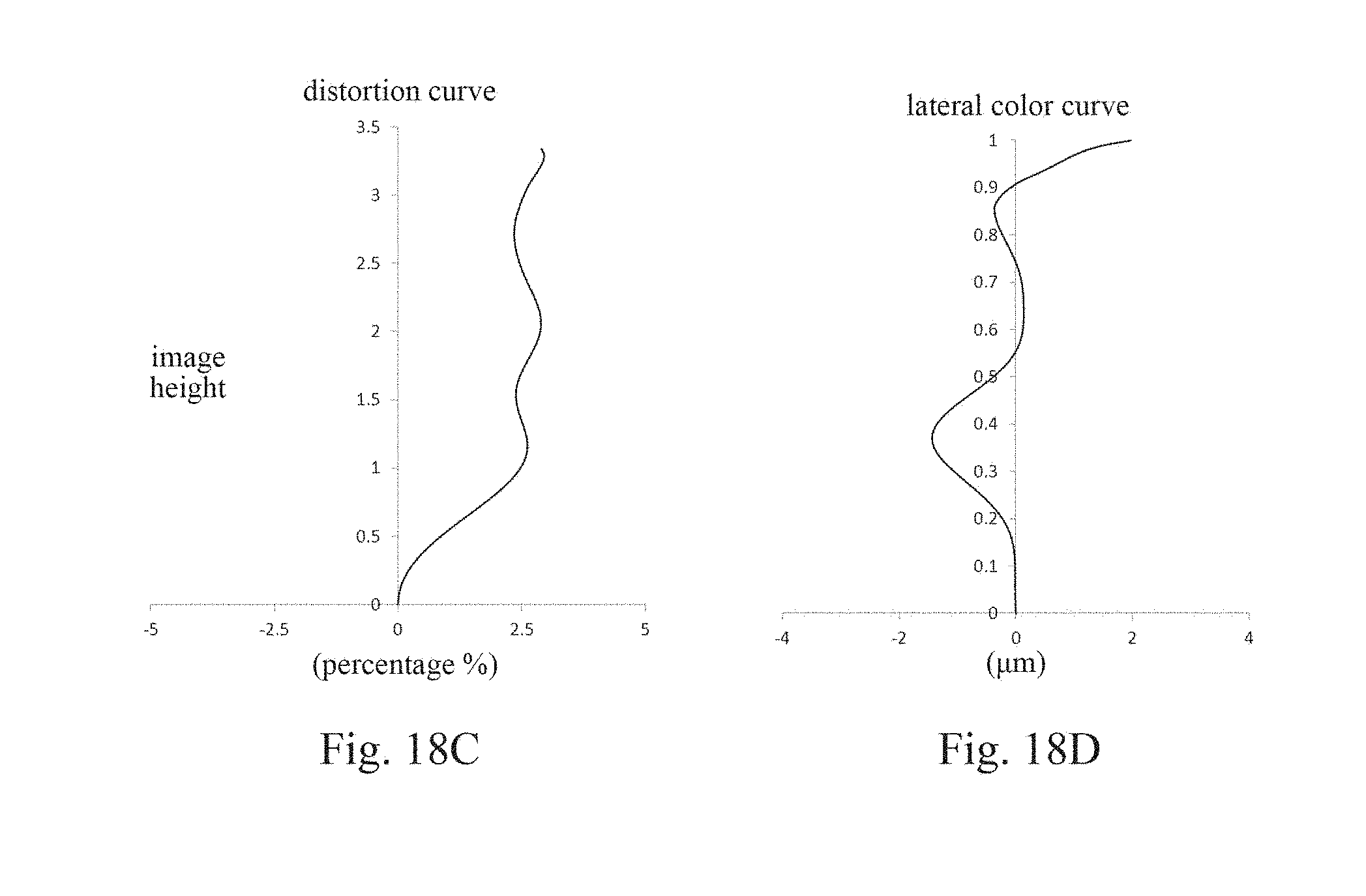
XML
uspto.report is an independent third-party trademark research tool that is not affiliated, endorsed, or sponsored by the United States Patent and Trademark Office (USPTO) or any other governmental organization. The information provided by uspto.report is based on publicly available data at the time of writing and is intended for informational purposes only.
While we strive to provide accurate and up-to-date information, we do not guarantee the accuracy, completeness, reliability, or suitability of the information displayed on this site. The use of this site is at your own risk. Any reliance you place on such information is therefore strictly at your own risk.
All official trademark data, including owner information, should be verified by visiting the official USPTO website at www.uspto.gov. This site is not intended to replace professional legal advice and should not be used as a substitute for consulting with a legal professional who is knowledgeable about trademark law.