Optical Imaging Lens Assembly
ZHOU; Xin ; et al.
U.S. patent application number 16/226954 was filed with the patent office on 2019-04-25 for optical imaging lens assembly. The applicant listed for this patent is ZHEJIANG SUNNY OPTICAL CO., LTD.. Invention is credited to Jianke WENREN, Jian YANG, Xin ZHOU.
| Application Number | 20190121098 16/226954 |
| Document ID | / |
| Family ID | 66170536 |
| Filed Date | 2019-04-25 |


View All Diagrams
| United States Patent Application | 20190121098 |
| Kind Code | A1 |
| ZHOU; Xin ; et al. | April 25, 2019 |
OPTICAL IMAGING LENS ASSEMBLY
Abstract
The present disclosure discloses an optical imaging lens assembly. The optical imaging lens assembly includes, sequentially along an optical axis from an object side to an image side, a first lens having a refractive power; a second lens having a positive refractive power; a third lens having a refractive power; a fourth lens having a refractive power; a fifth lens having a refractive power; a sixth lens having a refractive power; a seventh lens having a refractive power, wherein an image-side surface of the seventh lens is a convex surface; and an eighth lens having a refractive power. There is an air spacing between any two adjacent lenses in the first to eighth lenses. A total effective focal length f of the optical imaging lens assembly and an entrance pupil diameter EPD of the optical imaging lens assembly satisfy: f/EPD.ltoreq.2.0.
| Inventors: | ZHOU; Xin; (Ningbo City, CN) ; YANG; Jian; (Ningbo City, CN) ; WENREN; Jianke; (Ningbo City, CN) | ||||||||||
| Applicant: |
|
||||||||||
|---|---|---|---|---|---|---|---|---|---|---|---|
| Family ID: | 66170536 | ||||||||||
| Appl. No.: | 16/226954 | ||||||||||
| Filed: | December 20, 2018 |
Related U.S. Patent Documents
| Application Number | Filing Date | Patent Number | ||
|---|---|---|---|---|
| PCT/CN2018/092874 | Jun 26, 2018 | |||
| 16226954 | ||||
| Current U.S. Class: | 1/1 |
| Current CPC Class: | G02B 9/64 20130101; G02B 13/0045 20130101 |
| International Class: | G02B 13/00 20060101 G02B013/00; G02B 9/64 20060101 G02B009/64 |
Foreign Application Data
| Date | Code | Application Number |
|---|---|---|
| Oct 24, 2017 | CN | 201711000982.4 |
| Oct 24, 2017 | CN | 201721377058.3 |
Claims
1. An optical imaging lens assembly comprising, sequentially along an optical axis from an object side to an image side, a first lens having a refractive power; a second lens having a positive refractive power; a third lens having a refractive power; a fourth lens having a refractive power; a fifth lens having a refractive power; a sixth lens having a refractive power; a seventh lens having a refractive power, wherein an image-side surface of the seventh lens is a convex surface; and an eighth lens having a refractive power; wherein there is an air spacing between any two adjacent lenses in the first to eighth lenses, and a total effective focal length f of the optical imaging lens assembly and an entrance pupil diameter EPD of the optical imaging lens assembly satisfy: f/EPD.ltoreq.2.0.
2. The optical imaging lens assembly according to claim 1, wherein the total effective focal length f of the optical imaging lens assembly and an effective focal length f2 of the second lens satisfy: 1.0<f/f2<1.5.
3. The optical imaging lens assembly according to claim 2, wherein the effective focal length f2 of the second lens and a center thickness CT2 of the second lens on the optical axis satisfy: 5.5.ltoreq.f2/CT2<6.5.
4. The optical imaging lens assembly according to claim 1, wherein an object-side surface of the first lens is a convex surface, and the total effective focal length f of the optical imaging lens assembly and a radius of curvature R1 of the object-side surface of the first lens satisfy: 2<f/R1<2.5.
5. The optical imaging lens assembly according to claim 1, wherein an image-side surface of the eighth lens is a concave surface, and the total effective focal length f of the optical imaging lens assembly and a radius of curvature R16 of the image-side surface of the eighth lens satisfy: 1.5<f/R16<3.0.
6. The optical imaging lens assembly according to claim 5, wherein the radius of curvature R16 of the image-side surface of the eighth lens and a radius of curvature R14 of the image-side surface of the seventh lens satisfy: 1.0<|R16/R14|<1.5.
7. The optical imaging lens assembly according to claim 1, wherein an effective focal length f8 of the eighth lens and a center thickness CT8 of the eighth lens on the optical axis satisfy: -11<f8/CT8<-7.
8. The optical imaging lens assembly according to claim 7, wherein a sagittal height SAG82 of an image-side surface of the eighth lens at a maximum effective semi-diameter, and the center thickness CT8 of the eighth lens on the optical axis satisfy: -3.0<SAG82/CT8<-1.5.
9. The optical imaging lens assembly according to claim 1, wherein a total track length TTL of the optical imaging lens assembly and half of a diagonal length ImgH of an effective pixel area on an image plane of the optical imaging lens assembly satisfy: TTL/ImgH.ltoreq.1.50.
10. The optical imaging lens assembly according to claim 9, wherein the center thickness CT2 of the second lens on the optical axis and a center thickness CT3 of the third lens on the optical axis satisfy: 2.5<CT2/CT3<3.5.
11. An optical imaging lens assembly comprising, sequentially along an optical axis from an object side to an image side, a first lens having a refractive power, wherein an object-side surface of the first lens is a convex surface; a second lens having a positive refractive power, wherein an object-side surface of the second lens is a convex surface; a third lens having a refractive power; a fourth lens having a refractive power; a fifth lens having a refractive power; a sixth lens having a refractive power; a seventh lens having a refractive power, wherein an image-side surface of the seventh lens is a convex surface; and an eighth lens having a refractive power, wherein an image-side surface of the eighth lens is a concave surface; wherein a total effective focal length f of the optical imaging lens assembly, an effective focal length fl of the first lens, and an effective focal length f2 of the second lens satisfy: 1.0<|f/f1|+|f/f2|<1.5.
12. The optical imaging lens assembly according to claim 11, wherein the effective focal length f2 of the second lens and a center thickness CT2 of the second lens on the optical axis satisfy: 5.5.ltoreq.f2/CT2<6.5.
13. The optical imaging lens assembly according to claim 11, wherein the total effective focal length f of the optical imaging lens assembly and the effective focal length f2 of the second lens satisfy: 1.0<f/f2<1.5.
14. The optical imaging lens assembly according to claim 11, wherein an effective focal length f8 of the eighth lens and a center thickness CT8 of the eighth lens on the optical axis satisfy: -11<f8/CT8<-7.
15. The optical imaging lens assembly according to claim 11, wherein a sagittal height SAG82 of the image-side surface of the eighth lens at a maximum effective semi-diameter, and the center thickness CT8 of the eighth lens on the optical axis satisfy: -3.0<SAG82/CT8<-1.5.
16. The optical imaging lens assembly according to claim 11, wherein the total effective focal length f of the optical imaging lens assembly and a radius of curvature R1 of the object-side surface of the first lens satisfy: 2<f/R1<2.5.
17. The optical imaging lens assembly according to claim 11, wherein the total effective focal length f of the optical imaging lens assembly and a radius of curvature R16 of the image-side surface of the eighth lens satisfy: 1.5<f/R16<3.0.
18. The optical imaging lens assembly according to claim 11, wherein a radius of curvature R16 of the image-side surface of the eighth lens and a radius of curvature R14 of the image-side surface of the seventh lens satisfy: 1.0<|R16/R14|<1.5.
19. The optical imaging lens assembly according to claim 11, wherein a center thickness CT2 of the second lens on the optical axis and a center thickness CT3 of the third lens on the optical axis satisfy: 2.5<CT2/CT3<3.5.
20. The optical imaging lens assembly according to claim 16, wherein a total track length TTL of the optical imaging lens assembly and half of a diagonal length ImgH of an effective pixel area on an image plane of the optical imaging lens assembly satisfy: TTL/ImgH.ltoreq.1.50.
Description
CROSS-REFERENCE TO RELATED APPLICATIONS
[0001] This application is a continuation of International Application No. PCT/CN2018/092874, filed on Jun. 26, 2018, which claims the priorities and rights to Chinese Patent Application No. 201711000982.4 and Chinese Patent Application No. 201721377058.3 filed with China National Intellectual Property Administration (CNIPA) on Oct. 24, 2017. All of the aforementioned applications are hereby incorporated by reference in their entireties.
TECHNICAL FIELD
[0002] The present disclosure relates to an optical imaging lens assembly, and more specifically to an optical imaging lens assembly including eight lenses.
BACKGROUND
[0003] With the improvement in performance and reduction in size of the chips such as CCDs (charge-coupled devices) or CMOS (complementary metal-oxide semiconductor) elements, corresponding requirements on miniaturization and high imaging quality of the counterpart optical imaging lens assemblies have been brought forward.
[0004] In addition, with the popularity of portable electronic devices such as cell phones or digital cameras, the range of applications of the portable electronic products has become more and more wide, and thus, corresponding requirements on large aperture and high resolution of the counterpart optical imaging lens assemblies have also been brought forward.
SUMMARY
[0005] The present disclosure provides an optical imaging lens assembly which may be applicable to portable electronic products and may at least or partially sovle at least one of the above disadvantages in the existing technology, for example, an imaging lens assembly having a large aperture.
[0006] According to an aspect, the present disclosure provides an optical imaging lens assembly. The optical imaging lens assembly includes, sequentially along an optical axis from an object side to an image side, a first lens having a refractive power; a second lens having a positive refractive power; a third lens having a refractive power; a fourth lens having a refractive power; a fifth lens having a refractive power; a sixth lens having a refractive power; a seventh lens having a refractive power, wherein an image-side surface of the seventh lens may be a convex surface; and an eighth lens having a refractive power. There is an air spacing between any two adjacent lenses in the first to eighth lenses. A total effective focal length f of the optical imaging lens assembly and an entrance pupil diameter EPD of the optical imaging lens assembly may satisfy: f/EPD.ltoreq.2.0.
[0007] In an implementation, the total effective focal length f of the optical imaging lens assembly and an effective focal length f2 of the second lens may satisfy: 1.0<f/f2<1.5.
[0008] In an implementation, the total effective focal length f of the optical imaging lens assembly, an effective focal length f1 of the first lens, and the effective focal length f2 of the second lens may satisfy: 1.0<|f/f1|+|f/f2|<1.5.
[0009] In an implementation, the effective focal length f2 of the second lens and a center thickness CT2 of the second lens on the optical axis may satisfy: 5.5.ltoreq.f2/CT2<6.5.
[0010] In an implementation, an object-side surface of the second lens may be a convex surface. The effective focal length f2 of the second lens and a radius of curvature R3 of the object-side surface of the second lens may satisfy: 1.5<f2/R3<2.5.
[0011] In an implementation, an object-side surface of the first lens may be a convex surface. The total effective focal length f of the optical imaging lens assembly and a radius of curvature R1 of the object-side surface of the first lens may satisfy: 2<f/R1<2.5.
[0012] In an implementation, an image-side surface of the eighth lens may be a concave surface. The total effective focal length f of the optical imaging lens assembly and a radius of curvature R16 of the image-side surface of the eighth lens may satisfy: 1.5<f/R16<3.0.
[0013] In an implementation, the radius of curvature R16 of the image-side surface of the eighth lens and a radius of curvature R14 of the image-side surface of the seventh lens may satisfy: 1.0<|R16/R14|<1.5.
[0014] In an implementation, a radius of curvature R13 of an object-side surface of the seventh lens and the radius of curvature R14 of the image-side surface of the seventh lens may satisfy: -33<(R13+R14)/(R13-R14)<1.
[0015] In an implementation, an effective focal length f8 of the eighth lens and a center thickness CT8 of the eighth lens on the optical axis may satisfy: -11<f8/CT8<-7.
[0016] In an implementation, a sagittal height SAG82 of the image-side surface of the eighth lens at a maximum effective semi-diameter, and the center thickness CT8 of the eighth lens on the optical axis may satisfy: -3.0<SAG82/CT8<-1.5.
[0017] In an implementation, a total track length TTL of the optical imaging lens assembly and half of a diagonal length ImgH of an effective pixel area on an image plane of the optical imaging lens assembly may satisfy: TTL/ImgH.ltoreq.1.50.
[0018] In an implementation, the center thickness CT2 of the second lens on the optical axis and a center thickness CT3 of the third lens on the optical axis may satisfy: 2.5<CT2/CT3<3.5.
[0019] In an implementation, a spacing distance T45 on the optical axis between the fourth lens and the fifth lens and a spacing distance T67 on the optical axis between the sixth lens and the seventh lens may satisfy: 1.0<T45/T67<4.5.
[0020] According to another aspect, the present disclosure provides an optical imaging lens assembly. The optical imaging lens assembly includes, sequentially along an optical axis from an object side to an image side, a first lens having a refractive power, wherein an object-side surface of the first lens may be a convex surface; a second lens having a positive refractive power, wherein an object-side surface of the second lens may be a convex surface; a third lens having a refractive power; a fourth lens having a refractive power; a fifth lens having a refractive power; a sixth lens having a refractive power; a seventh lens having a refractive power, wherein an image-side surface of the seventh lens may be a convex surface; and an eighth lens having a refractive power, wherein an image-side surface of the eighth lens may be a concave surface. A total effective focal length f of the optical imaging lens assembly, an effective focal length f1 of the first lens, and an effective focal length f2 of the second lens may satisfy: 1.0<|f/f1|+|f/f2|<1.5.
[0021] According to another aspect, the present disclosure provides an optical imaging lens assembly. The optical imaging lens assembly includes, sequentially along an optical axis from an object side to an image side, a first lens having a refractive power; a second lens having a positive refractive power; a third lens having a refractive power; a fourth lens having a refractive power; a fifth lens having a refractive power; a sixth lens having a refractive power; a seventh lens having a refractive power, wherein an image-side surface of the seventh lens may be a convex surface; and an eighth lens having a refractive power. A total effective focal length f of the optical imaging lens assembly and an effective focal length f2 of the second lens may satisfy: 1.0<f/f2<1.5.
[0022] According to another aspect, the present disclosure provides an optical imaging lens assembly. The optical imaging lens assembly includes, sequentially along an optical axis from an object side to an image side, a first lens having a refractive power; a second lens having a positive refractive power; a third lens having a refractive power; a fourth lens having a refractive power; a fifth lens having a refractive power; a sixth lens having a refractive power; a seventh lens having a refractive power, wherein an image-side surface of the seventh lens may be a convex surface; and an eighth lens having a refractive power. An effective focal length f2 of the second lens and a center thickness CT2 of the second lens on the optical axis may satisfy: 5.5.ltoreq.f2/CT2<6.5.
[0023] According to another aspect, the present disclosure provides an optical imaging lens assembly. The optical imaging lens assembly includes, sequentially along an optical axis from an object side to an image side, a first lens having a refractive power; a second lens having a positive refractive power; a third lens having a refractive power; a fourth lens having a refractive power; a fifth lens having a refractive power; a sixth lens having a refractive power; a seventh lens having a refractive power, wherein an image-side surface of the seventh lens may be a convex surface; and an eighth lens having a refractive power. An effective focal length f2 of the second lens and a radius of curvature R3 of an object-side surface of the second lens may satisfy: 1.5<f2/R3<2.5.
[0024] According to another aspect, the present disclosure provides an optical imaging lens assembly. The optical imaging lens assembly includes, sequentially along an optical axis from an object side to an image side, a first lens having a refractive power; a second lens having a positive refractive power; a third lens having a refractive power; a fourth lens having a refractive power; a fifth lens having a refractive power; a sixth lens having a refractive power; a seventh lens having a refractive power, wherein an image-side surface of the seventh lens may be a convex surface; and an eighth lens having a refractive power. A total effective focal length f of the optical imaging lens assembly and a radius of curvature R1 of an object-side surface of the first lens may satisfy: 2<f/R1<2.5.
[0025] According to another aspect, the present disclosure provides an optical imaging lens assembly. The optical imaging lens assembly includes, sequentially along an optical axis from an object side to an image side, a first lens having a refractive power; a second lens having a positive refractive power; a third lens having a refractive power; a fourth lens having a refractive power; a fifth lens having a refractive power; a sixth lens having a refractive power; a seventh lens having a refractive power, wherein an image-side surface of the seventh lens may be a convex surface; and an eighth lens having a refractive power. A total effective focal length f of the optical imaging lens assembly and a radius of curvature R16 of an image-side surface of the eighth lens may satisfy: 1.5<f/R16<3.0.
[0026] According to another aspect, the present disclosure provides an optical imaging lens assembly. The optical imaging lens assembly includes, sequentially along an optical axis from an object side to an image side, a first lens having a refractive power; a second lens having a positive refractive power; a third lens having a refractive power; a fourth lens having a refractive power; a fifth lens having a refractive power; a sixth lens having a refractive power; a seventh lens having a refractive power, wherein an image-side surface of the seventh lens may be a convex surface; and an eighth lens having a refractive power. A radius of curvature R16 of an image-side surface of the eighth lens and a radius of curvature R14 of the image-side surface of the seventh lens may satisfy: 1.0<|R16/R14|<1.5.
[0027] According to another aspect, the present disclosure provides an optical imaging lens assembly. The optical imaging lens assembly includes, sequentially along an optical axis from an object side to an image side, a first lens having a refractive power; a second lens having a positive refractive power; a third lens having a refractive power; a fourth lens having a refractive power; a fifth lens having a refractive power; a sixth lens having a refractive power; a seventh lens having a refractive power, wherein an image-side surface of the seventh lens may be a convex surface; and an eighth lens having a refractive power. A radius of curvature R13 of an object-side surface of the seventh lens and a radius of curvature R14 of the image-side surface of the seventh lens may satisfy: -33<(R13+R14)/(R13-R14)<1.
[0028] According to another aspect, the present disclosure provides an optical imaging lens assembly. The optical imaging lens assembly includes, sequentially along an optical axis from an object side to an image side, a first lens having a refractive power; a second lens having a positive refractive power; a third lens having a refractive power; a fourth lens having a refractive power; a fifth lens having a refractive power; a sixth lens having a refractive power; a seventh lens having a refractive power, wherein an image-side surface of the seventh lens may be a convex surface; and an eighth lens having a refractive power. An effective focal length f8 of the eighth lens and a center thickness CT8 of the eighth lens on the optical axis may satisfy: -11<f8/CT8<-7.
[0029] According to another aspect, the present disclosure provides an optical imaging lens assembly. The optical imaging lens assembly includes, sequentially along an optical axis from an object side to an image side, a first lens having a refractive power; a second lens having a positive refractive power; a third lens having a refractive power; a fourth lens having a refractive power; a fifth lens having a refractive power; a sixth lens having a refractive power; a seventh lens having a refractive power, wherein an image-side surface of the seventh lens may be a convex surface; and an eighth lens having a refractive power. A sagittal height SAG82 of an image-side surface of the eighth lens at a maximum effective semi-diameter, and a center thickness CT8 of the eighth lens on the optical axis may satisfy: -3.0<SAG82/CT8<-1.5.
[0030] According to another aspect, the present disclosure provides an optical imaging lens assembly. The optical imaging lens assembly includes, sequentially along an optical axis from an object side to an image side, a first lens having a refractive power; a second lens having a positive refractive power; a third lens having a refractive power; a fourth lens having a refractive power; a fifth lens having a refractive power; a sixth lens having a refractive power; a seventh lens having a refractive power, wherein an image-side surface of the seventh lens may be a convex surface; and an eighth lens having a refractive power. A total track length TTL of the optical imaging lens assembly and half of a diagonal length ImgH of an effective pixel area on an image plane of the optical imaging lens assembly may satisfy: TTL/ImgH.ltoreq.1.50.
[0031] According to another aspect, the present disclosure provides an optical imaging lens assembly. The optical imaging lens assembly includes, sequentially along an optical axis from an object side to an image side, a first lens having a refractive power; a second lens having a positive refractive power; a third lens having a refractive power; a fourth lens having a refractive power; a fifth lens having a refractive power; a sixth lens having a refractive power; a seventh lens having a refractive power, wherein an image-side surface of the seventh lens may be a convex surface; and an eighth lens having a refractive power. A center thickness CT2 of the second lens on the optical axis and a center thickness CT3 of the third lens on the optical axis may satisfy: 2.5<CT2/CT3<3.5.
[0032] According to another aspect, the present disclosure provides an optical imaging lens assembly. The optical imaging lens assembly includes, sequentially along an optical axis from an object side to an image side, a first lens having a refractive power; a second lens having a positive refractive power; a third lens having a refractive power; a fourth lens having a refractive power; a fifth lens having a refractive power; a sixth lens having a refractive power; a seventh lens having a refractive power, wherein an image-side surface of the seventh lens may be a convex surface; and an eighth lens having a refractive power. A spacing distance T45 on the optical axis between the fourth lens and the fifth lens and a spacing distance T67 on the optical axis between the sixth lens and the seventh lens may satisfy: 1.0<T45/T67<4.5.
[0033] The present disclose adopts a plurality of lenses (e.g., eight lenses). By reasonably allocating the refractive powers and the surface types of the lenses, the center thicknesses of the lenses, the spacing distances on the axis between the lenses, etc., the optical imaging lens assembly has at least one of the beneficial effects such as miniaturization, large aperture, low sensitivity, good processibility, and high imaging quality.
BRIEF DESCRIPTION OF THE DRAWINGS
[0034] By describing non-limiting implementations below in detail and in combination with the accompanying drawings, other features, objectives and advantages of the present disclosure will be more apparent. In the accompanying drawings:
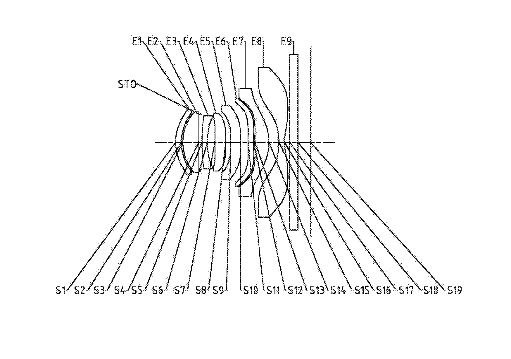
[0035] FIG. 1 is a schematic structural diagram illustrating an optical imaging lens assembly according to Embodiment 1 of the present disclosure;
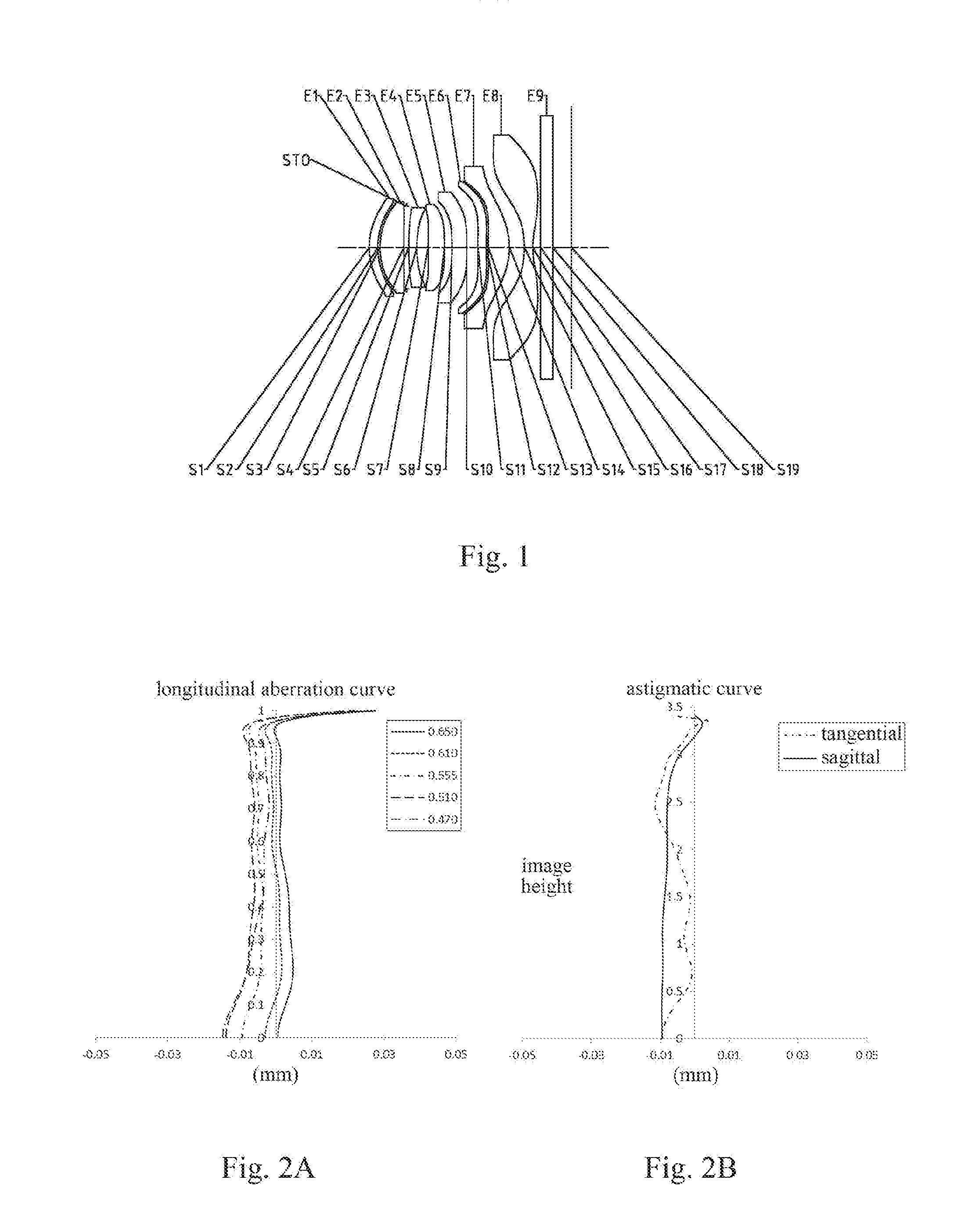
[0036] FIGS. 2A-2D respectively illustrate a longitudinal aberration curve, an astigmatic curve, a distortion curve, and a lateral color curve of the optical imaging lens assembly according to Embodiment 1;
[0037] FIG. 3 is a schematic structural diagram illustrating an optical imaging lens assembly according to Embodiment 2 of the present disclosure;
[0038] FIGS. 4A-4D respectively illustrate a longitudinal aberration curve, an astigmatic curve, a distortion curve, and a lateral color curve of the optical imaging lens assembly according to Embodiment 2;
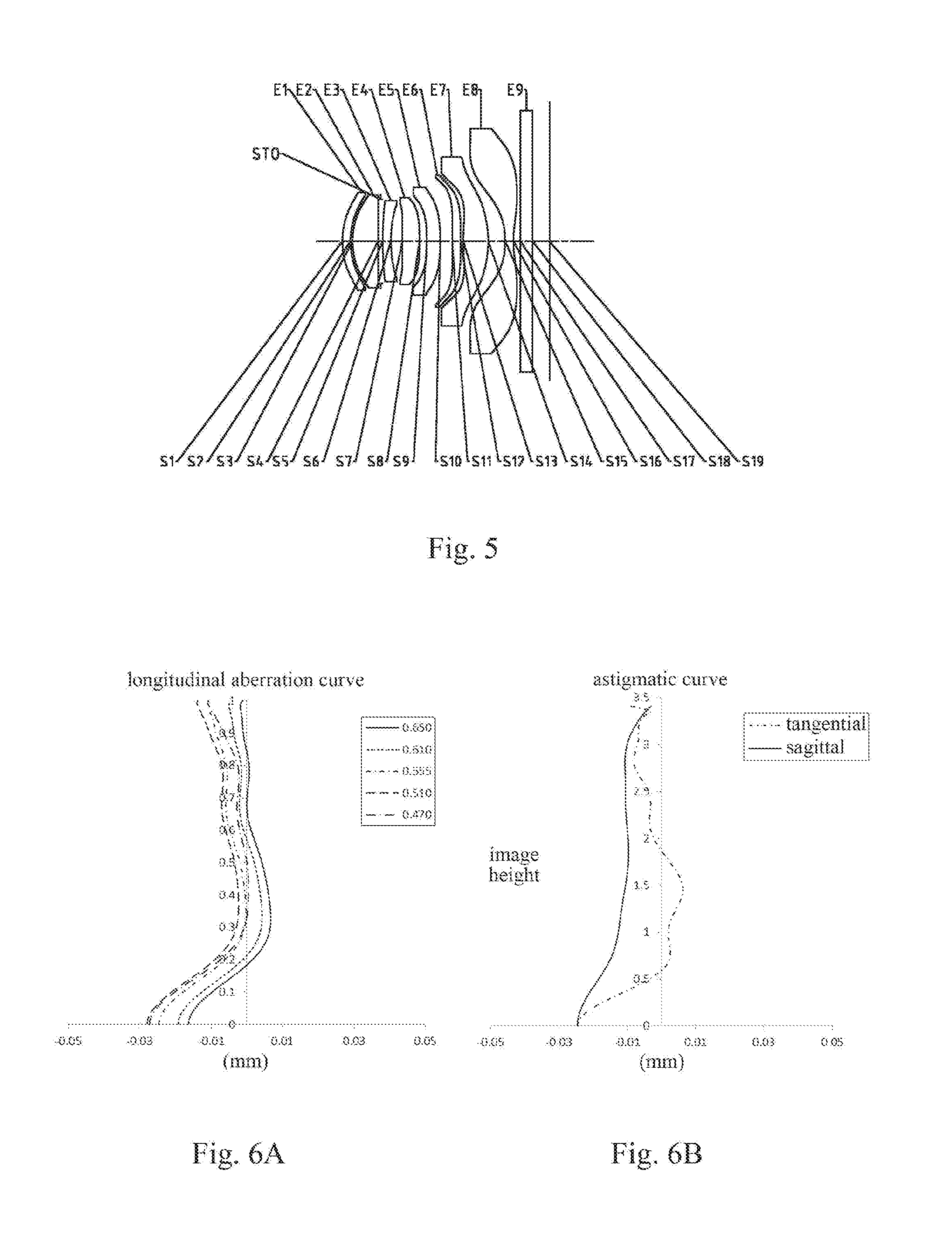
[0039] FIG. 5 is a schematic structural diagram illustrating an optical imaging lens assembly according to Embodiment 3 of the present disclosure;
[0040] FIGS. 6A-6D respectively illustrate a longitudinal aberration curve, an astigmatic curve, a distortion curve, and a lateral color curve of the optical imaging lens assembly according to Embodiment 3;
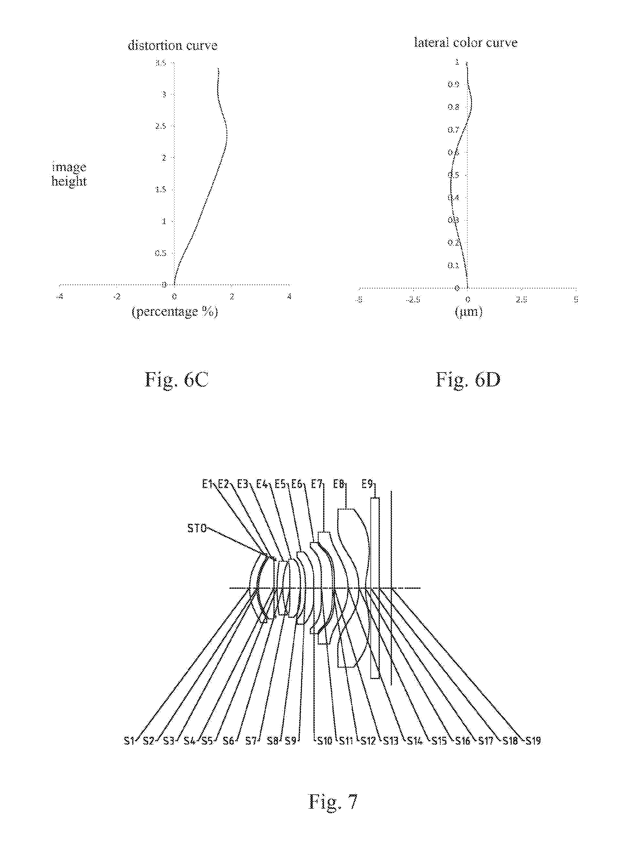
[0041] FIG. 7 is a schematic structural diagram illustrating an optical imaging lens assembly according to Embodiment 4 of the present disclosure;
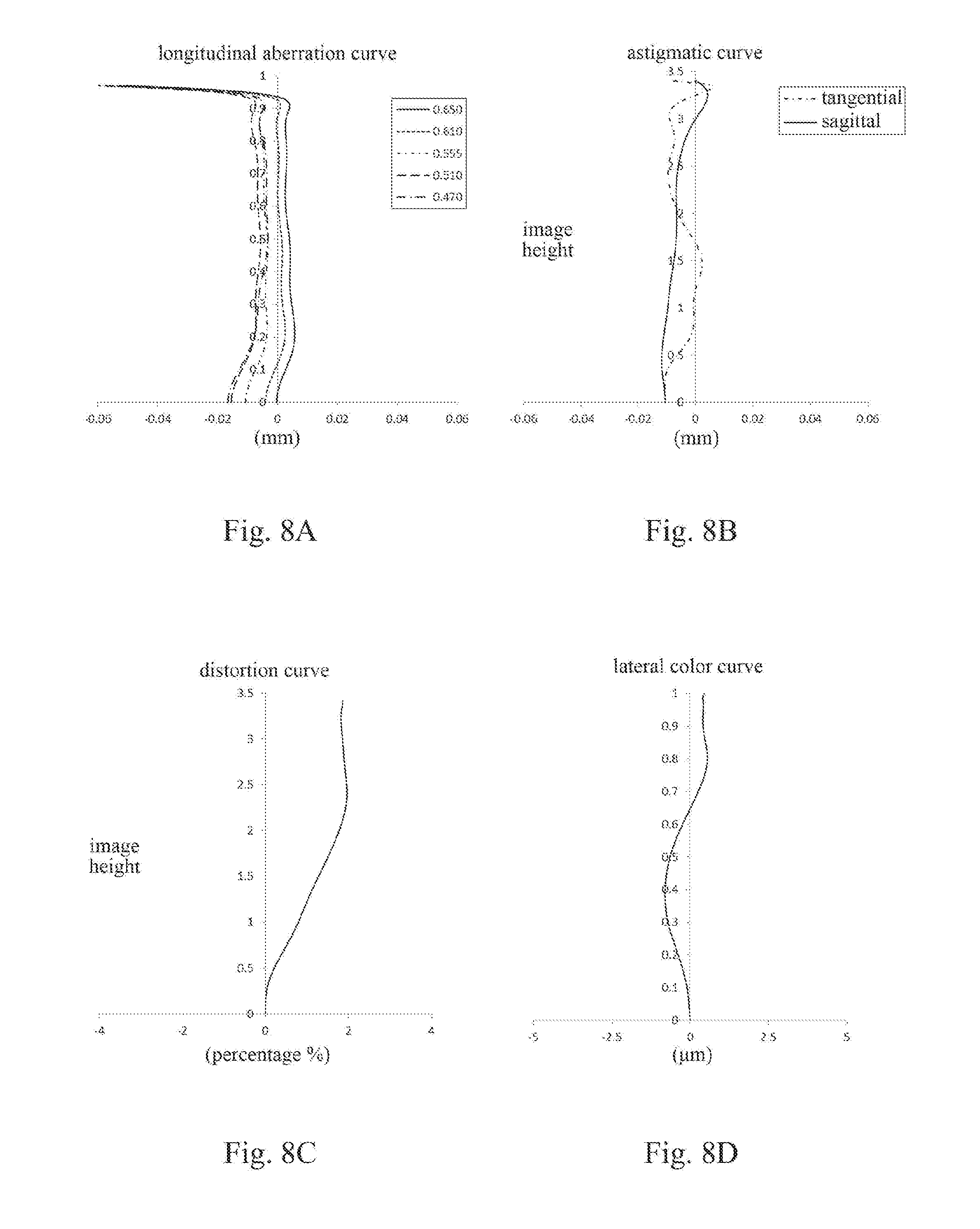
[0042] FIGS. 8A-8D respectively illustrate a longitudinal aberration curve, an astigmatic curve, a distortion curve, and a lateral color curve of the optical imaging lens assembly according to Embodiment 4;
[0043] FIG. 9 is a schematic structural diagram illustrating an optical imaging lens assembly according to Embodiment 5 of the present disclosure;
[0044] FIGS. 10A-10D respectively illustrate a longitudinal aberration curve, an astigmatic curve, a distortion curve, and a lateral color curve of the optical imaging lens assembly according to Embodiment 5;
[0045] FIG. 11 is a schematic structural diagram illustrating an optical imaging lens assembly according to Embodiment 6 of the present disclosure;
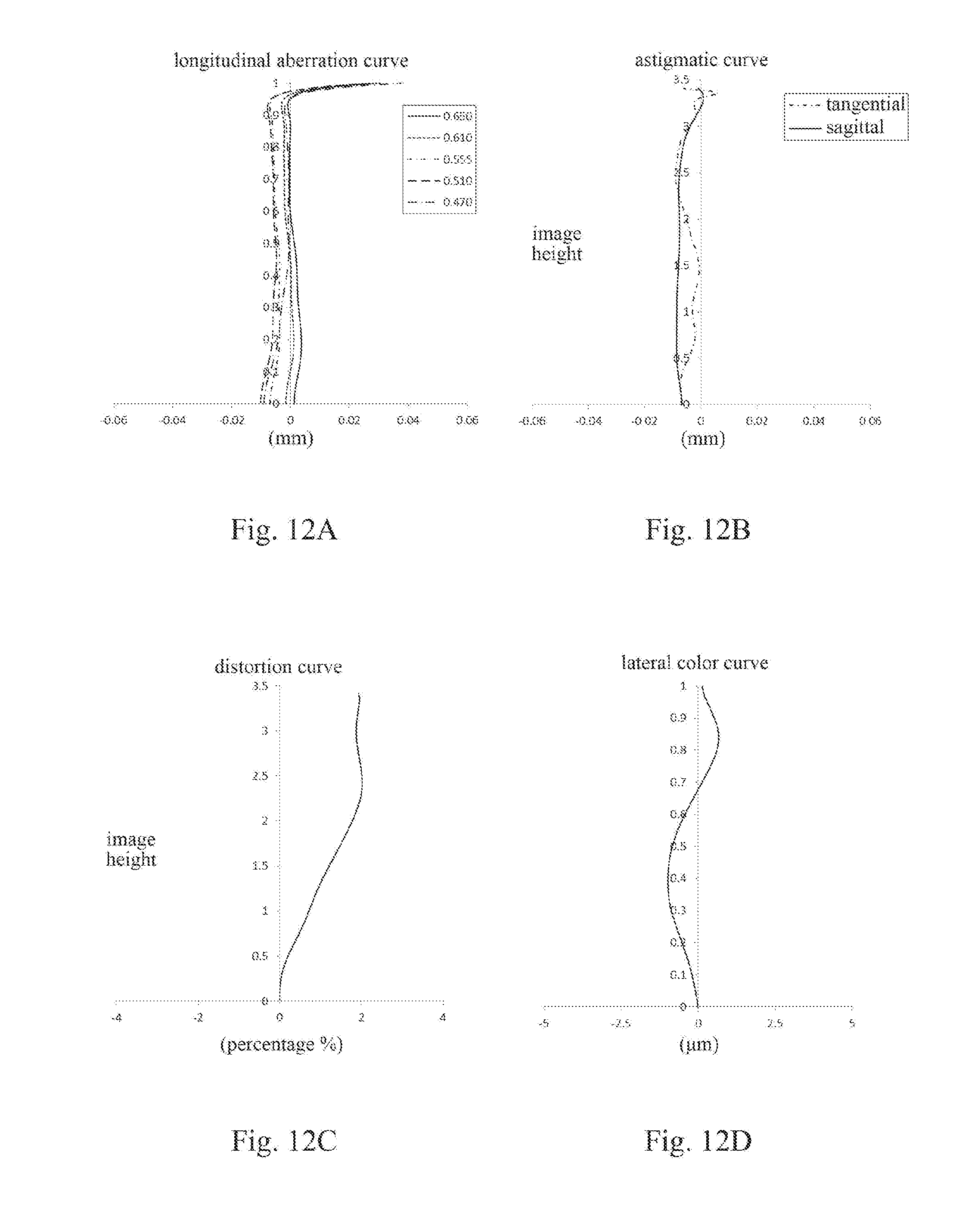
[0046] FIGS. 12A-12D respectively illustrate a longitudinal aberration curve, an astigmatic curve, a distortion curve, and a lateral color curve of the optical imaging lens assembly according to Embodiment 6;
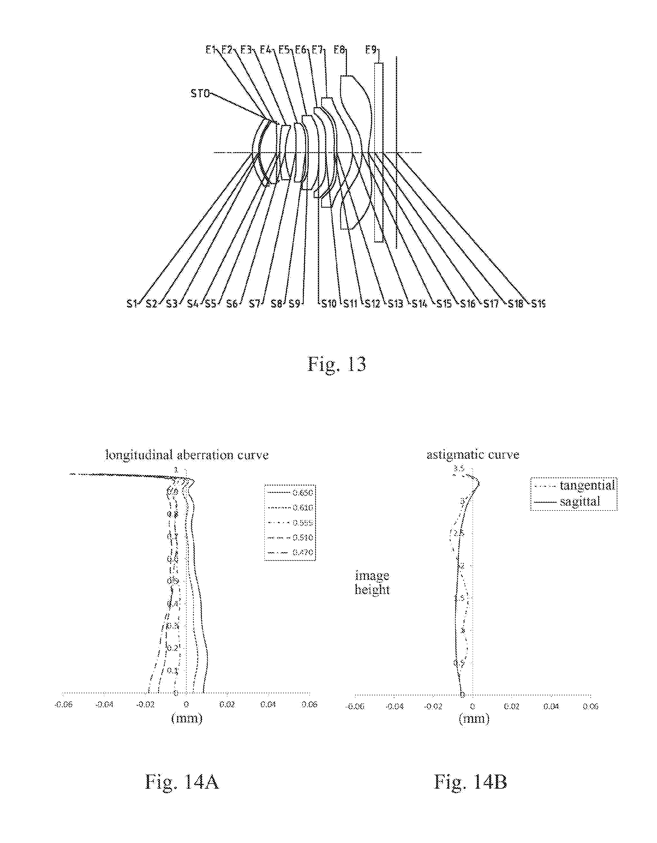
[0047] FIG. 13 is a schematic structural diagram illustrating an optical imaging lens assembly according to Embodiment 7 of the present disclosure;
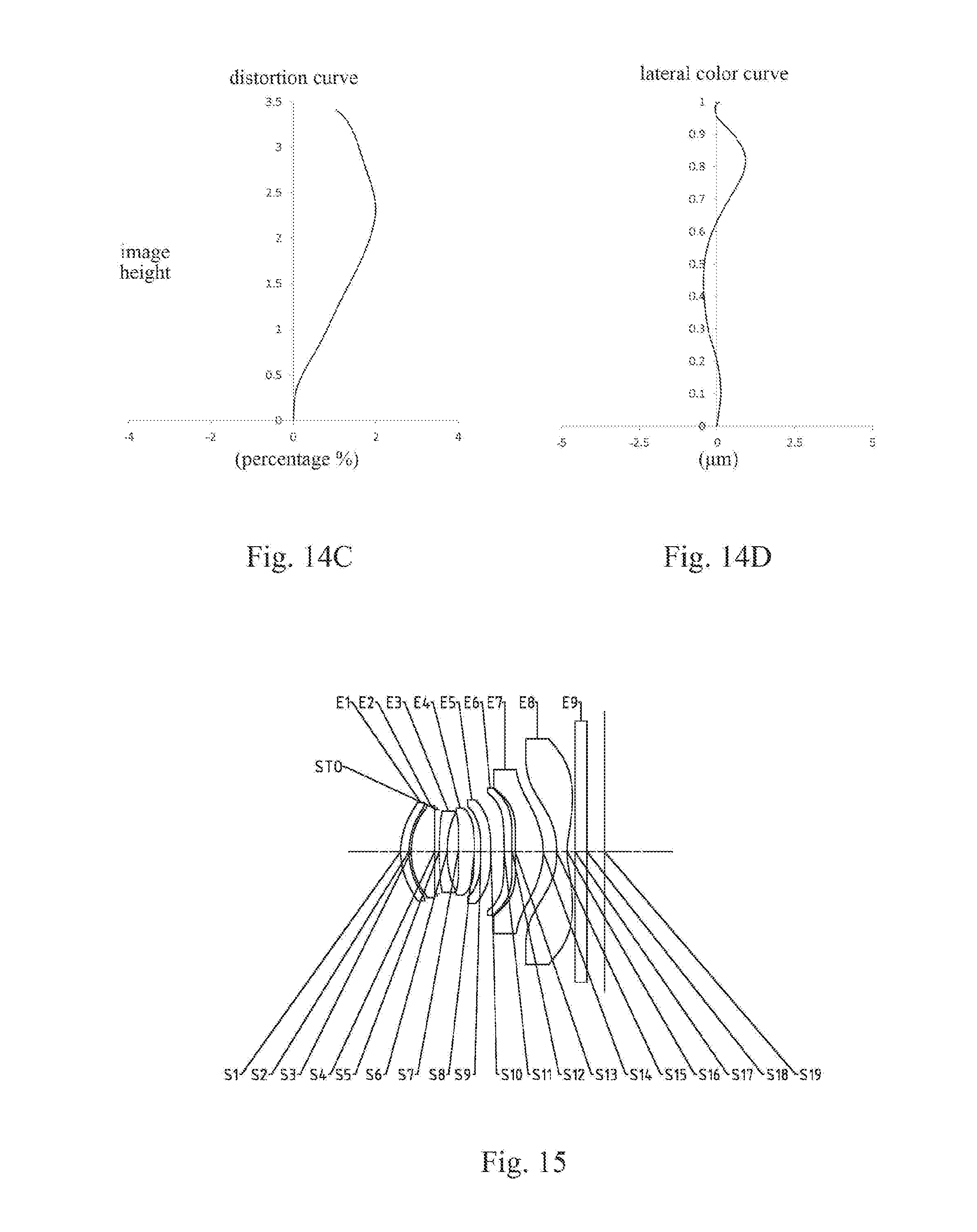
[0048] FIGS. 14A-14D respectively illustrate a longitudinal aberration curve, an astigmatic curve, a distortion curve, and a lateral color curve of the optical imaging lens assembly according to Embodiment 7;
[0049] FIG. 15 is a schematic structural diagram illustrating an optical imaging lens assembly according to Embodiment 8 of the present disclosure;
[0050] FIGS. 16A-16D respectively illustrate a longitudinal aberration curve, an astigmatic curve, a distortion curve, and a lateral color curve of the optical imaging lens assembly according to Embodiment 8;
[0051] FIG. 17 is a schematic structural diagram illustrating an optical imaging lens assembly according to Embodiment 9 of the present disclosure;
[0052] FIGS. 18A-18D respectively illustrate a longitudinal aberration curve, an astigmatic curve, a distortion curve, and a lateral color curve of the optical imaging lens assembly according to Embodiment 9;
[0053] FIG. 19 is a schematic structural diagram illustrating an optical imaging lens assembly according to Embodiment 10 of the present disclosure;
[0054] FIGS. 20A-20D respectively illustrate a longitudinal aberration curve, an astigmatic curve, a distortion curve, and a lateral color curve of the optical imaging lens assembly according to Embodiment 10;
[0055] FIG. 21 is a schematic structural diagram illustrating an optical imaging lens assembly according to Embodiment 11 of the present disclosure;
[0056] FIGS. 22A-22D respectively illustrate a longitudinal aberration curve, an astigmatic curve, a distortion curve, and a lateral color curve of the optical imaging lens assembly according to Embodiment 11;
[0057] FIG. 23 is a schematic structural diagram illustrating an optical imaging lens assembly according to Embodiment 12 of the present disclosure;
[0058] FIGS. 24A-24D respectively illustrate a longitudinal aberration curve, an astigmatic curve, a distortion curve, and a lateral color curve of the optical imaging lens assembly according to Embodiment 12;
[0059] FIG. 25 is a schematic structural diagram illustrating an optical imaging lens assembly according to Embodiment 13 of the present disclosure; and
[0060] FIGS. 26A-26D respectively illustrate a longitudinal aberration curve, an astigmatic curve, a distortion curve, and a lateral color curve of the optical imaging lens assembly according to Embodiment 13.
DETAILED DESCRIPTION
[0061] For a better understanding of the present disclosure, various aspects of the present disclosure will be described in more detail with reference to the accompanying drawings. It should be understood that the detailed description is merely an illustration for the exemplary implementations of the present disclosure rather than a limitation to the scope of the present disclosure in any way. Throughout the specification, the same reference numerals designate the same elements. The expression "and/or" includes any and all combinations of one or more of the associated listed items.
[0062] It should be noted that in the specification, the expressions, such as "first," "second," and "third" are only used to distinguish one feature from another, rather than represent any limitations to the features. Thus, the first lens discussed below may also be referred to as the second lens or the third lens without departing from the teachings of the present disclosure.
[0063] In the accompanying drawings, the thicknesses, sizes and shapes of the lenses have been slightly exaggerated for the convenience of explanation. Specifically, shapes of spherical surfaces or aspheric surfaces shown in the accompanying drawings are shown by examples. That is, the shapes of the spherical surfaces or the aspheric surfaces are not limited to the shapes of the spherical surfaces or the aspheric surfaces shown in the accompanying drawings. The accompanying drawings are merely illustrative and not strictly drawn to scale.
[0064] Herein, the paraxial area refers to an area near the optical axis. If a surface of a lens is a convex surface and a position of the convex surface is not defined, it indicates that the surface of the lens is a convex surface at least in the paraxial area; and if a surface of a lens is a concave surface and a position of the concave surface is not defined, it indicates that the surface of the lens is a concave surface at least in the paraxial area. The surface closest to the object in each lens is referred to as the object-side surface, and the surface closest to the image plane in each lens is referred to as the image-side surface.
[0065] It should be further understood that the terms "comprising," "including," "having" and variants thereof, when used in the specification, specify the presence of stated features, elements and/or components, but do not exclude the presence or addition of one or more other features, elements, components and/or combinations thereof. In addition, expressions such as "at least one of," when preceding a list of listed features, modify the entire list of features rather than an individual element in the list. Further, the use of "may," when describing the implementations of the present disclosure, relates to "one or more implementations of the present disclosure." Also, the term "exemplary" is intended to refer to an example or illustration.
[0066] Unless otherwise defined, all terms (including technical and scientific terms) used herein have the same meaning as commonly understood by those of ordinary skill in the art to which the present disclosure belongs. It should be further understood that terms (i.e., those defined in commonly used dictionaries) should be interpreted as having a meaning that is consistent with their meaning in the context of the relevant art and will not be interpreted in an idealized or overly formal sense unless expressly so defined herein.
[0067] It should also be noted that the embodiments in the present disclosure and the features in the embodiments may be combined with each other on a non-conflict basis. The present disclosure will be described below in detail with reference to the accompanying drawings and in combination with the embodiments.
[0068] Features, principles, and other aspects of the present disclosure are described below in detail.
[0069] The optical imaging lens assembly according to exemplary implementations of the present disclosure may include, for example, eight lenses (i.e., a first lens, a second lens, a third lens, a fourth lens, a fifth lens, a sixth lens, a seventh lens, and an eighth lens) having refractive powers. The eight lenses are arranged in sequence along an optical axis from an object side to an image side. There is an air spacing between any two adjacent lenses in the first to eighth lenses.
[0070] In the exemplary implementations, an object-side surface of the first lens may be a convex surface, and an image-side surface of the first lens may be a concave surface.
[0071] In the exemplary implementations, the second lens may have a positive refractive power. An object-side surface of the second lens may be a convex surface, and an image-side surface of the second lens may be a concave surface.
[0072] In the exemplary implementations, the third lens may have a negative refractive power. An object-side surface of the third lens may be a convex surface, and an image-side surface of the third lens may be a concave surface.
[0073] In the exemplary implementations, an image-side surface of the seventh lens may be a convex surface.
[0074] In the exemplary implementations, the eighth lens may have a negative refractive power. An object-side surface of the eighth lens may be a concave surface, and an image-side surface of the eighth lens may be a concave surface.
[0075] In the exemplary implementations, the optical imaging lens assembly of the present disclosure may satisfy the conditional expression f/EPD.ltoreq.2.0. Here, f is the total effective focal length of the optical imaging lens assembly, and EPD is the entrance pupil diameter of the optical imaging lens assembly. More specifically, f and EPD may further satisfy: 1.67.ltoreq.f/EPD.ltoreq.1.90. When the lens assembly is configured to satisfy the conditional expression f/EPD.ltoreq.2.0, the lens assembly may have the advantage of large aperture, to enhance the imaging effect of the lens assembly in an environment of insufficient light. At the same time, it is also conducive to reducing the aberration of the edge field.
[0076] In the exemplary implementations, the optical imaging lens assembly of the present disclosure may satisfy the conditional expression TTL/ImgH.ltoreq.1.50. Here, TTL is the total track length of the optical imaging lens assembly (i.e., the distance on the optical axis from the center of the object-side surface of the first lens to the image plane of the optical imaging lens assembly), and ImgH is the half of the diagonal length of the effective pixel area on the image plane. More specifically, TTL and ImgH may further satisfy: 1.44.ltoreq.TTL/ImgH.ltoreq.1.50. When the conditional expression TTL/ImgH.ltoreq.1.50 is satisfied, the size of the imaging system can be effectively compressed, which ensures that the imaging system has the characteristic of compact structure.
[0077] In the exemplary implementations, the optical imaging lens assembly of the present disclosure may satisfy the conditional expression 1.0<|f/f1|+|f/f2|<1.5. Here, f is the total effective focal length of the optical imaging lens assembly, and f1 is the effective focal length of the first lens, and f2 is the effective focal length of the second lens. More specifically, f, f1, and f2 may further satisfy: 1.1<|f/f1|+|f/f2|<1.3, for example, 1.18.ltoreq.|f/f1|+|f/f2|.ltoreq.1.28. Reasonably allocating the refractive power of the first lens and the refractive power of the second lens is conducive to reducing the deflection angle of the light, thereby reducing the sensitivity of the system.
[0078] In the exemplary implementations, the optical imaging lens assembly of the present disclosure may satisfy the conditional expression 1.0<f/f2<1.5. Here, f is the total effective focal length of the optical imaging lens assembly, and f2 is the effective focal length of the second lens. More specifically, f and f2 may further satisfy: 1.1<f/f2<1.3, for example, 1.15.ltoreq.f/f2.ltoreq.1.26. By reasonably the refractive power of the second lens, the imaging system may have a good capability to balance the field curvature.
[0079] In the exemplary implementations, the optical imaging lens assembly of the present disclosure may satisfy the conditional expression 1.5<f/R16<3.0. Here, f is the total effective focal length of the optical imaging lens assembly, and R16 is the radius of curvature of the image-side surface of the eighth lens. More specifically, f and R16 may further satisfy: 1.7<f/R16<2.6, for example, 1.72.ltoreq.f/R16.ltoreq.2.52. Reasonably arranging the radius of curvature of the image-side surface of the eighth lens is conducive to the matching between the imaging system and commonly used chips.
[0080] In the exemplary implementations, the optical imaging lens assembly of the present disclosure may satisfy the conditional expression 2.5<CT2/CT3<3.5. Here, CT2 is the center thickness of the second lens on the optical axis, and CT3 is the center thickness of the third lens on the optical axis. More specifically, CT2 and CT3 may further satisfy: 2.7<CT2/CT3<3.2, for example, 2.76.ltoreq.CT2/CT3.ltoreq.3.17. By reasonably the center thicknesses of the second lens and the third lens, the imaging system can have a good capability to balance the comatic aberration.
[0081] In the exemplary implementations, the optical imaging lens assembly of the present disclosure may satisfy the conditional expression -11<f8/CT8<-7. Here, f8 is the effective focal length of the eighth lens, and CT8 is the center thickness of the eighth lens on the optical axis. More specifically, f8 and CT8 may further satisfy: -10.13.ltoreq.f8/CT8.ltoreq.-7.44. By reasonably controlling the ratio of f8 to CT8, the size of the back end of the imaging system can be effectively reduced.
[0082] In the exemplary implementations, the optical imaging lens assembly of the present disclosure may satisfy the conditional expression 2<f/R1<2.5. Here, f is the total effective focal length of the optical imaging lens assembly, and R1 is the radius of curvature of the object-side surface of the first lens. More specifically, f and R1 may further satisfy: 2.1<f/R1<2.4, for example, 2.16.ltoreq.f/R1.ltoreq.2.38. By reasonably arranging the radius of curvature of the object-side surface of the first lens, the aberration of the imaging system can be effectively balanced, thereby improving the optical performance of the imaging system.
[0083] In the exemplary implementations, the optical imaging lens assembly of the present disclosure may satisfy the conditional expression 1.0<|R16/R14|<1.5. Here, R16 is the radius of curvature of the image-side surface of the eighth lens, and R14 is the radius of curvature of the image-side surface of the seventh lens. More specifically, R16 and R14 may further satisfy: 1.0<|R16/R14|<1.2, for example, 1.01.ltoreq.|R16/R14|.ltoreq.1.11. By reasonably arranging the radius of curvature of the seventh lens and the radius of curvature of the eighth lens, the field curvature and the distortion of the imaging system can be better balanced.
[0084] In the exemplary implementations, the optical imaging lens assembly of the present disclosure may satisfy the conditional expression -3.0<SAG82/CT8<-1.5. Here, SAG82 is the sagittal height of the image-side surface of the eighth lens at the maximum effective semi-diameter (i.e., the distance on the optical axis from the intersection of the image-side surface of the eighth lens and the optical axis to the vertex of the maximum effective semi-diameter of the image-side surface of the eighth lens). More specifically, SAG82 and CT8 may further satisfy: -2.8<SAG82/CT8<-1.6, for example, -2.71.ltoreq.SAG82/CT8.ltoreq.-1.66. By reasonably controlling the ratio of SAG82 to CT8, the chief ray angle of the system is reasonably adjusted, so that the relative brightness of the imaging system can be effectively improved, thereby improving the sharpness of the image plane.
[0085] In the exemplary implementations, the optical imaging lens assembly of the present disclosure may satisfy the conditional expression 5.5.ltoreq.f2/CT2<6.5. Here, f2 is the effective focal length of the second lens, and CT2 is the center thickness of the second lens on the optical axis. More specifically, f2 and CT2 may further satisfy: 5.51.ltoreq.f2/CT2.ltoreq.6.44. By reasonably controlling the ratio of f2 to CT2, the deflection of light can be effectively controlled, thereby reducing the size of the front end of the optical imaging system.
[0086] In the exemplary implementations, the optical imaging lens assembly of the present disclosure may satisfy the conditional expression 1.5<f2/R3<2.5. Here, f2 is the effective focal length of the second lens, and R3 is the radius of curvature of the object-side surface of the second lens. More specifically, f2 and R3 may further satisfy: 1.9<f2/R3<2.1, for example, 1.95.ltoreq.f2/R3.ltoreq.2.02. By reasonably arranging the radius of curvature of the object-side surface of the second lens, the imaging system can have a good capability to balance the astigmatism.
[0087] In the exemplary implementations, the optical imaging lens assembly of the present disclosure may satisfy the conditional expression 1.0<T45/T67<4.5. Here, T45 is the spacing distance on the optical axis between the fourth lens and the fifth lens, and T67 is the spacing distance on the optical axis between the sixth lens and the seventh lens. More specifically, T45 and T67 may further satisfy: 1.0<T45/T67<4.3, for example, 1.03.ltoreq.T45/T67.ltoreq.4.22. By reasonablly controlling the ratio of T45 to T67, the imaging system can have a good capability to balance the dispersion.
[0088] In the exemplary implementations, the optical imaging lens assembly of the present disclosure may satisfy the conditional expression -33<(R13+R14)/(R13-R14)<1. Here, R13 is the radius of curvature of the object-side surface of the seventh lens, R14 is the radius of curvature of the image-side surface of the seventh lens. More specifically, R13 and R14 may further satisfy: -32.33.ltoreq.(R13+R14)/(R13-R14).ltoreq.0.99. By reasonably arranging the radius of curvature of the object-side surface of the seventh lens and the radius of curvature of the image-side surface of the seventh lens, the imaging system can be better matched with the chief ray angle of the chip.
[0089] In the exemplary implementations, the optical imaging lens assembly may further include at least one diaphragm, to improve the imaging quality of the lens assembly. For example, the diaphragm may be disposed between the second lens and the third lens.
[0090] Alternatively, the optical imaging lens assembly described above may further include an optical filter for correcting color deviations and/or a protective glass for protecting a photosensitive element on the image plane.
[0091] The optical imaging lens assembly according to the above implementations of the present disclosure may use a plurality of lenses, for example, the eight lenses described above. By reasonably allocating the refractive powers and the surface types of the lenses, the center thicknesses of the lenses, the spacing distances on the axis between the lenses, etc., it is possible to effectively reduce the size of the lens assembly, reduce the sensitivity of the lens assembly and improve the processibility of the lens assembly, which makes the lens assembly more conducive to production and processing and can be applied to the portable electronic produt. At the same time, the optical imaging lens assembly with the above configurations further has characteristics of miniaturization, large aperture, and high imaging quality. When the optical imaging lens assembly is matched with the imaging chip having high resolution, the good imaging effect can be achieved.
[0092] In the implementations of the present disclosure, the surface of each lens is an aspheric surface. The aspheric lens is characterized in that the curvature continuously changes from the center of the lens to the periphery. Different from a spherical lens having a constant curvature from the center of the lens to the periphery, the aspheric lens has a better radius-of-curvature characteristic, and has advantages of improving the distortion aberration and the astigmatic aberration. The use of the aspheric lens can eliminate as much as possible the aberrations that occur during the imaging, thereby improving the imaging quality.
[0093] However, it should be understood by those skilled in the art that the various results and advantages described in the present specification may be obtained by changing the number of the lenses constituting the optical imaging lens assembly without departing from the technical solution claimed by the present disclosure. For example, although the optical imaging lens assembly having eight lenses is described as an example in the implementations, the optical imaging lens assembly is not limited to include eight lenses. If desired, the optical imaging lens assembly may also include other numbers of lenses.
[0094] Specific embodiments of the optical imaging lens assembly that may be applied to the above implementations are further described below with reference to the accompanying drawings.
Embodiment 1
[0095] An optical imaging lens assembly according to Embodiment 1 of the present disclosure is described below with reference to FIGS. 1-2D. FIG. 1 is a schematic structural diagram illustrating the optical imaging lens assembly according to Embodiment 1 of the present disclosure.
[0096] As shown in FIG. 1, the optical imaging lens assembly according to the exemplary implementations of the present disclosure includes, sequentially along an optical axis from an object side to an image side, a first lens E1, a second lens E2, a diaphragm STO, a third lens E3, a fourth lens E4, a fifth lens E5, a sixth lens E6, a seventh lens E7, an eighth lens E8, an optical filter E9, and an image plane S19.
[0097] The first lens E1 has a positive refractive power, an object-side surface S1 of the first lens E1 is a convex surface, and an image-side surface S2 of the first lens E1 is a concave surface. The second lens E2 has a positive refractive power, an object-side surface S3 of the second lens E2 is a convex surface, and an image-side surface S4 of the second lens E2 is a concave surface. The third lens E3 has a negative refractive power, an object-side surface S5 of the third lens E3 is a convex surface, and an image-side surface S6 of the third lens E3 is a concave surface. The fourth lens E4 has a positive refractive power, an object-side surface S7 of the fourth lens E4 is a convex surface, and an image-side surface S8 of the fourth lens E4 is a convex surface. The fifth lens E5 has a negative refractive power, an object-side surface S9 of the fifth lens E5 is a concave surface, and an image-side surface S10 of the fifth lens E5 is a convex surface. The sixth lens E6 has a negative refractive power, an object-side surface S11 of the sixth lens E6 is a convex surface, and an image-side surface S12 of the sixth lens E6 is a concave surface. The seventh lens E7 has a positive refractive power, an object-side surface S13 of the seventh lens E7 is a convex surface, and an image-side surface S14 of the seventh lens E7 is a convex surface. The eighth lens E8 has a negative refractive power, an object-side surface S15 of the eighth lens E8 is a concave surface, and an image-side surface S16 of the eighth lens E8 is a concave surface. The optical filter E9 has an object-side surface S17 and an image-side surface S18. Light from an object sequentially passes through the surfaces S1-S18 and finally forms an image on the image plane S19.
[0098] Table 1 shows the surface type, the radius of curvature, the thickness, the material and the conic coefficient of each lens of the optical imaging lens assembly in Embodiment 1. The radius of curvature and the thickness are both shown in millimeters (mm).
TABLE-US-00001 TABLE 1 material radius of refractive abbe conic surfaces number surface type curvature thickness index number coefficient OBJ spherical infinite infinite S1 aspheric 1.7514 0.2085 1.55 64.1 -0.0870 S2 aspheric 1.7298 0.0500 -0.0484 S3 aspheric 1.6853 0.5803 1.55 64.1 0.0223 S4 aspheric 15.7406 0.0663 71.3048 STO spherical infinite 0.0500 S5 aspheric 4.9354 0.2000 1.67 20.4 5.0469 S6 aspheric 2.4564 0.2762 0.0534 S7 aspheric 18.7304 0.3945 1.55 64.1 99.0000 S8 aspheric -11.8642 0.1853 93.6685 S9 aspheric -9.6203 0.3586 1.67 20.4 -86.9214 S10 aspheric -32.6361 0.2707 99.0000 S11 aspheric 14.5602 0.2045 1.55 64.1 -99.0000 S12 aspheric 12.5442 0.0500 -68.4873 S13 aspheric 11.8368 0.5112 1.55 64.1 -90.9432 S14 aspheric -1.5924 0.3626 -7.4261 S15 aspheric -2.8760 0.2023 1.54 55.7 -2.2684 S16 aspheric 1.6619 0.1917 -11.6039 S17 spherical infinite 0.3000 1.52 64.2 S18 spherical infinite 0.4493 S19 spherical infinite
[0099] As may be obtained from Table 1, the object-side surface and the image-side surface of any lens in the first to eighth lenses E1-E8 are both aspheric surfaces. In this embodiment, the surface type x of each aspheric surface may be defined using, but not limited to, the following formula:
x = ch 2 1 + 1 - ( k + 1 ) c 2 h 2 + Aih i . ( 1 ) ##EQU00001##
[0100] Here, x is the sag-the axis-component of the displacement of the surface from the aspheric vertex, when the surface is at height h from the optical axis; c is the paraxial curvature of the aspheric surface, and c=1/R (i.e., the paraxial curvature c is the reciprocal of the radius of curvature R in Table 1 above); k is the conic coefficient (given in Table 1); and Ai is the correction coefficient of the i.sup.th order of the aspheric surface. Table 2 below shows the high-order coefficients A.sub.4, A.sub.6, A.sub.8, A.sub.10, A.sub.12, A.sub.14, A.sub.16, A.sub.18, and A.sub.20 applicable to the aspheric surfaces S1-S16 in Embodiment 1.
TABLE-US-00002 TABLE 2 surface number A4 A6 A8 A10 A12 S1 -2.8757E-03 -2.6715E-02 7.0465E-02 -9.4968E-02 5.7426E-02 S2 -2.2838E-03 -1.8213E-01 9.4190E-01 -2.6138E+00 4.7822E+00 S3 -8.2854E-03 -9.6483E-02 4.7157E-01 -1.1060E+00 1.6421E+00 S4 -7.0370E-02 9.3251E-02 -3.0568E-02 -3.8895E-01 1.3450E+00 S5 -1.4159E-01 2.6893E-01 -2.2207E-01 -2.1377E-01 1.3725E+00 S6 -9.0205E-02 1.8492E-01 1.7001E-01 -1.9054E+00 6.7992E+00 S7 -7.6478E-02 -3.8747E-02 4.3032E-01 -2.8152E+00 9.6268E+00 S8 -1.3540E-01 1.0858E-01 -4.4991E-01 1.0751E+00 -1.9829E+00 S9 -2.4491E-01 2.6719E-01 -8.0746E-01 2.0135E+00 -3.5877E+00 S10 -2.1414E-01 1.6899E-01 -2.8003E-01 4.9096E-01 -6.4260E-01 S11 -9.6204E-02 -1.3289E-02 -9.0648E-02 3.0570E-01 -4.2358E-01 S12 -9.5969E-02 1.3525E-02 -1.5051E-01 3.7645E-01 -4.7731E-01 S13 -1.0827E-01 5.1696E-02 -1.5786E-01 3.0429E-01 -3.5620E-01 S14 -7.8363E-02 4.5589E-02 -4.7405E-02 5.6774E-02 -3.9560E-02 S15 -2.0315E-01 1.5775E-01 -7.5563E-02 2.9300E-02 -8.4139E-03 S16 -1.3032E-01 1.0120E-01 -5.6012E-02 2.1259E-02 -5.5486E-03 surface number A14 A16 A18 A20 S1 5.6138E-03 -3.8444E-02 2.3434E-02 -4.6951E-03 S2 -5.7128E+00 4.2255E+00 -1.7542E+00 3.0995E-01 S3 -1.4981E+00 7.2660E-01 -1.0704E-01 -2.7156E-02 S4 -2.3179E+00 2.2832E+00 -1.2018E+00 2.5745E-01 S5 -2.9645E+00 3.5857E+00 -2.3315E+00 6.2558E-01 S6 -1.4244E+01 1.7988E+01 -1.2531E+01 3.6982E+00 S7 -1.9848E+01 2.4443E+01 -1.6568E+01 4.7635E+00 S8 2.4051E+00 -1.7362E+00 6.7712E-01 -1.1701E-01 S9 4.0526E+00 -2.6395E+00 8.8949E-01 -1.2006E-01 S10 5.4312E-01 -2.6854E-01 6.9301E-02 -7.0717E-03 S11 3.2724E-01 -1.4923E-01 3.7584E-02 -4.0009E-03 S12 3.5450E-01 -1.5689E-01 3.8229E-02 -3.9186E-03 S13 2.5463E-01 -1.0980E-01 2.6191E-02 -2.6315E-03 S14 1.6183E-02 -3.8799E-03 5.0395E-04 -2.7350E-05 S15 1.6247E-03 -1.9723E-04 1.3613E-05 -4.0881E-07 S16 9.7033E-04 -1.0824E-04 6.9500E-06 -1.9499E-07
[0101] In Embodiment 1, the total effective focal length f of the optical imaging lens assembly satisfies: f=3.99 mm. The effective focal length f1 of the first lens E1 satisfies: f1=106.47 mm. The effective focal length f2 of the second lens E2 satisfies: f2=3.41 mm. The effective focal length f3 of the third lens E3 satisfies: f3=-7.59 mm. The effective focal length f4 of the fourth lens E4 satisfies: f4=13.37 mm. The effective focal length f5 of the fifth lens E5 satisfies: f5=-20.62 mm. The effective focal length f6 of the sixth lens E6 satisfies: f6=-172.11 mm. The effective focal length f7 of the seventh lens E7 satisfies: f7=2.61 mm. The effective focal length f8 of the eighth lens E8 satisfies: f8=-1.93 mm. The total track length TTL (i.e., the distance on the optical axis from the center of the object-side surface S1 of the first lens E1 to the image plane S19) of the optical imaging lens assembly satisfies: TTL=4.91 mm. The half of the diagonal length ImgH of the effective pixel area on the image plane S19 of the optical imaging lens assembly satisfies: ImgH=3.41 mm.
[0102] The optical imaging lens assembly in Embodiment 1 satisfies:
[0103] f/EPD=1.80, wherein f is the total effective focal length of the optical imaging lens assembly, and EPD is the entrance pupil diameter of the optical imaging lens assembly;
[0104] TTL/ImgH=1.44, wherein TTL is the total track length of the optical imaging lens assembly, and ImgH is the half of the diagonal length of the effective pixel area on the image plane S19;
[0105] |f/f1|+|f/f2|=1.21, wherein f is the total effective focal length of the optical imaging lens assembly, f1 is the effective focal length of the first lens E1, and f2 is the effective focal length of the second lens E2;
[0106] f/f2=1.17, wherein f is the total effective focal length of the optical imaging lens assembly, and f2 is the effective focal length of the second lens E2;
[0107] f/R16=2.40, wherein f is the total effective focal length of the optical imaging lens assembly, and R16 is the radius of curvature of the image-side surface S16 of the eighth lens E8;
[0108] CT2/CT3=2.90, wherein CT2 is the center thickness of the second lens E2 on the optical axis, and CT3 is the center thickness of the third lens E3 on the optical axis;
[0109] f8/CT8=-9.55, wherein f8 is the effective focal length of the eighth lens E8, and CT8 is the center thickness of the eighth lens E8 on the optical axis;
[0110] f/R1=2.28, wherein f is the total effective focal length of the optical imaging lens assembly, and R1 is the radius of curvature of the object-side surface S1 of the first lens E1;
[0111] |R16/R14|=1.04, wherein R16 is the radius of curvature of the image-side surface S16 of the eighth lens E8, and R14 is the radius of curvature of the image-side surface S14 of the seventh lens E7;
[0112] SAG82/CT8=-2.63, wherein SAG82 is the sagittal height SAG82 of the image-side surface S16 of the eighth lens E8 at the maximum effective semi-diameter, and CT8 is the center thickness of the eighth lens on the optical axis;
[0113] f2/CT2=5.87, wherein f2 is the effective focal length of the second lens E2, and CT2 is the center thickness of the second lens E2 on the optical axis;
[0114] f2/R3=2.02, wherein f2 is the effective focal length of the second lens E2, and R3 is the radius of curvature of the object-side surface S3 of the second lens E2;
[0115] T45/T67=3.71, wherein T45 is the spacing distance on the optical axis between the fourth lens E4 and the fifth lens E5, and T67 is the spacing distance on the optical axis between the sixth lens E6 and the seventh lens E7; and
[0116] (R13+R14)/(R13-R14)=0.76, wherein R13 is the radius of curvature of the object-side surface S13 of the seventh lens E7, and R14 is the radius of curvature of the image-side surface S14 of the seventh lens E7.
[0117] FIG. 2A illustrates the longitudinal aberration curve of the optical imaging lens assembly according to Embodiment 1, representing deviations of focal points of light of different wavelengths converged after passing through the lens assembly. FIG. 2B illustrates the astigmatic curve of the optical imaging lens assembly according to Embodiment 1, representing a curvature of the tangential image plane and a curvature of the sagittal image plane. FIG. 2C illustrates the distortion curve of the optical imaging lens assembly according to Embodiment 1, representing amounts of distortion at different viewing angles. FIG. 2D illustrates the lateral color curve of the optical imaging lens assembly according to Embodiment 1, representing deviations of different image heights on the image plane after light passes through the lens assembly. It can be seen from FIGS. 2A-2D that the optical imaging lens assembly according to Embodiment 1 can achieve a good imaging quality.
Embodiment 2
[0118] An optical imaging lens assembly according to Embodiment 2 of the present disclosure is described below with reference to FIGS. 3-4D. In this embodiment and the following embodiments, for the purpose of brevity, the description of parts similar to those in Embodiment 1 will be omitted. FIG. 3 is a schematic structural diagram illustrating the optical imaging lens assembly according to Embodiment 2 of the present disclosure.
[0119] As shown in FIG. 3, the optical imaging lens assembly according to the exemplary implementations of the present disclosure includes, sequentially along an optical axis from an object side to an image side, a first lens E1, a second lens E2, a diaphragm STO, a third lens E3, a fourth lens E4, a fifth lens E5, a sixth lens E6, a seventh lens E7, an eighth lens E8, an optical filter E9, and an image plane S19.
[0120] The first lens E1 has a positive refractive power, an object-side surface S1 of the first lens E1 is a convex surface, and an image-side surface S2 of the first lens E1 is a concave surface. The second lens E2 has a positive refractive power, an object-side surface S3 of the second lens E2 is a convex surface, and an image-side surface S4 of the second lens E2 is a concave surface. The third lens E3 has a negative refractive power, an object-side surface S5 of the third lens E3 is a convex surface, and an image-side surface S6 of the third lens E3 is a concave surface. The fourth lens E4 has a positive refractive power, an object-side surface S7 of the fourth lens E4 is a convex surface, and an image-side surface S8 of the fourth lens E4 is a convex surface. The fifth lens E5 has a negative refractive power, an object-side surface S9 of the fifth lens E5 is a concave surface, and an image-side surface S10 of the fifth lens E5 is a convex surface. The sixth lens E6 has a negative refractive power, an object-side surface S11 of the sixth lens E6 is a convex surface, and an image-side surface S12 of the sixth lens E6 is a concave surface. The seventh lens E7 has a positive refractive power, an object-side surface S13 of the seventh lens E7 is a convex surface, and an image-side surface S14 of the seventh lens E7 is a convex surface. The eighth lens E8 has a negative refractive power, an object-side surface S15 of the eighth lens E8 is a concave surface, and an image-side surface S16 of the eighth lens E8 is a concave surface. The optical filter E9 has an object-side surface S17 and an image-side surface S18. Light from an object sequentially passes through the surfaces S1-S18 and finally forms an image on the image plane S19.
[0121] Table 3 shows the surface type, the radius of curvature, the thickness, the material and the conic coefficient of each lens of the optical imaging lens assembly in Embodiment 2. The radius of curvature and the thickness are both shown in millimeters (mm).
TABLE-US-00003 TABLE 3 material radius of refractive abbe conic surface number surface type curvature thickness index number coefficient OBJ spherical infinite infinite S1 aspheric 1.8772 0.2000 1.55 64.1 -0.0525 S2 aspheric 1.8441 0.0500 -0.0570 S3 aspheric 1.7967 0.6333 1.55 64.1 0.0605 S4 aspheric 25.6286 0.0644 90.6150 STO spherical infinite 0.0500 S5 aspheric 7.6179 0.2000 1.67 20.4 14.0413 S6 aspheric 3.0067 0.2945 -0.5490 S7 aspheric 20.0582 0.4218 1.55 64.1 99.0000 S8 aspheric -9.7419 0.1737 58.5639 S9 aspheric -6.9938 0.3254 1.67 20.4 -99.0000 S10 aspheric -13.2191 0.3031 -96.9382 S11 aspheric 16.3734 0.2000 1.55 64.1 94.1609 S12 aspheric 14.5954 0.0721 35.8418 S13 aspheric 4.9064 0.6047 1.55 64.1 -48.1315 S14 aspheric -2.3021 0.4184 -12.8717 S15 aspheric -2.0651 0.2000 1.54 55.7 -2.4160 S16 aspheric 2.3660 0.1719 -17.3050 S17 spherical infinite 0.3000 1.52 64.2 S18 spherical infinite 0.4167 S19 spherical infinite
[0122] As may be obtained from Table 3, in Embodiment 2, the object-side surface and the image-side surface of any lens in the first to eighth lenses E1-E8 are both aspheric surfaces. Table 4 shows the high-order coefficients applicable to each aspheric surface in Embodiment 2. The surface type of each aspheric surface may be defined by the formula (1) given in Embodiment 1.
TABLE-US-00004 TABLE 4 surface number A4 A6 A8 A10 A12 S1 -1.0986E-02 1.3416E-02 -5.9978E-02 1.7564E-01 -3.1039E-01 S2 -2.5269E-02 3.3919E-02 -4.5690E-02 1.7371E-01 -4.2270E-01 S3 -2.1968E-02 5.6931E-02 -1.5586E-01 4.2150E-01 -7.6254E-01 S4 -3.7321E-02 3.5651E-02 5.8630E-02 -4.0803E-01 9.5364E-01 S5 -9.3311E-02 1.5849E-01 -7.0679E-02 -3.5459E-01 1.1719E+00 S6 -6.1789E-02 1.1253E-01 7.9954E-02 -7.7033E-01 2.1120E+00 S7 -8.0342E-02 8.2776E-02 -4.8266E-01 1.1733E+00 -1.7006E+00 S8 -1.0771E-01 6.2642E-02 -3.3207E-01 8.0573E-01 -1.5634E+00 S9 -2.3470E-01 2.1313E-01 -4.6656E-01 7.4924E-01 -9.0053E-01 S10 -1.7715E-01 6.8830E-02 7.4420E-02 -3.7404E-01 6.3665E-01 S11 -7.4997E-02 8.0128E-03 2.2727E-02 -3.7437E-02 -2.7954E-03 S12 -1.3713E-01 4.9404E-02 -8.5346E-02 2.2264E-01 -3.2583E-01 S13 -7.4819E-02 8.6327E-03 -1.5165E-01 3.1120E-01 -3.3514E-01 S14 -2.0690E-02 2.1127E-03 -6.9187E-02 8.5820E-02 -4.9790E-02 S15 -1.2986E-01 6.2864E-02 -3.4212E-02 2.6119E-02 -1.1544E-02 S16 -1.0110E-01 6.9683E-02 -3.5212E-02 1.2681E-02 -3.2228E-03 surface number A14 A16 A18 A20 S1 3.2128E-01 -1.9534E-01 6.3553E-02 -8.5205E-03 S2 5.4675E-01 -3.8975E-01 1.4006E-01 -1.9655E-02 S3 8.5567E-01 -5.7584E-01 2.1305E-01 -3.3807E-02 S4 -1.2397E+00 9.4403E-01 -3.8996E-01 6.6732E-02 S5 -1.8007E+00 1.5731E+00 -7.4328E-01 1.4651E-01 S6 -3.2753E+00 3.0702E+00 -1.6086E+00 3.6416E-01 S7 1.1826E+00 -9.6908E-03 -4.5907E-01 1.8287E-01 S8 2.0668E+00 -1.6573E+00 7.3560E-01 -1.4325E-01 S9 6.7043E-01 -1.4052E-01 -1.2098E-01 5.5998E-02 S10 -5.9936E-01 3.3553E-01 -1.0617E-01 1.4776E-02 S11 3.7185E-02 -2.9448E-02 9.4035E-03 -1.0876E-03 S12 2.6496E-01 -1.2339E-01 3.0807E-02 -3.1780E-03 S13 2.1794E-01 -8.7105E-02 1.9678E-02 -1.8983E-03 S14 1.7027E-02 -3.5128E-03 4.0268E-04 -1.9622E-05 S15 2.8272E-03 -3.9418E-04 2.9615E-05 -9.3691E-07 S16 5.5360E-04 -6.0727E-05 3.8340E-06 -1.0578E-07
[0123] In Embodiment 2, the total effective focal length f of the optical imaging lens assembly satisfies: f=4.06 mm. The effective focal length f1 of the first lens E1 satisfies: f1=169.37 mm. The effective focal length f2 of the second lens E2 satisfies: f2=3.51 mm. The effective focal length f3 of the third lens E3 satisfies: f3=-7.58 mm. The effective focal length f4 of the fourth lens E4 satisfies: f4=12.07 mm. The effective focal length f5 of the fifth lens E5 satisfies: f5=-22.74 mm. The effective focal length f6 of the sixth lens E6 satisfies: f6=-256.41 mm. The effective focal length f7 of the seventh lens E7 satisfies: f7=2.96 mm. The effective focal length f8 of the eighth lens E8 satisfies: f8=-2.02 mm. The total track length TTL (i.e., the distance on the optical axis from the center of the object-side surface S1 of the first lens E1 to the image plane S19) of the optical imaging lens assembly satisfies: TTL=5.10 mm. The half of the diagonal length ImgH of the effective pixel area on the image plane S19 of the optical imaging lens assembly satisfies: ImgH=3.41 mm.
[0124] FIG. 4A illustrates the longitudinal aberration curve of the optical imaging lens assembly according to Embodiment 2, representing deviations of focal points of light of different wavelengths converged after passing through the lens assembly. FIG. 4B illustrates the astigmatic curve of the optical imaging lens assembly according to Embodiment 2, representing a curvature of the tangential image plane and a curvature of the sagittal image plane. FIG. 4C illustrates the distortion curve of the optical imaging lens assembly according to Embodiment 2, representing amounts of distortion at different viewing angles. FIG. 4D illustrates the lateral color curve of the optical imaging lens assembly according to Embodiment 2, representing deviations of different image heights on the image plane after light passes through the lens assembly. It can be seen from FIGS. 4A-4D that the optical imaging lens assembly according to Embodiment 2 can achieve a good imaging quality.
Embodiment 3
[0125] An optical imaging lens assembly according to Embodiment 3 of the present disclosure is described below with reference to FIGS. 5-6D. FIG. 5 is a schematic structural diagram illustrating the optical imaging lens assembly according to Embodiment 3 of the present disclosure.
[0126] As shown in FIG. 5, the optical imaging lens assembly according to the exemplary implementations of the present disclosure includes, sequentially along an optical axis from an object side to an image side, a first lens E1, a second lens E2, a diaphragm STO, a third lens E3, a fourth lens E4, a fifth lens E5, a sixth lens E6, a seventh lens E7, an eighth lens E8, an optical filter E9, and an image plane S19.
[0127] The first lens E1 has a positive refractive power, an object-side surface S1 of the first lens E1 is a convex surface, and an image-side surface S2 of the first lens E1 is a concave surface. The second lens E2 has a positive refractive power, an object-side surface S3 of the second lens E2 is a convex surface, and an image-side surface S4 of the second lens E2 is a concave surface. The third lens E3 has a negative refractive power, an object-side surface S5 of the third lens E3 is a convex surface, and an image-side surface S6 of the third lens E3 is a concave surface. The fourth lens E4 has a positive refractive power, an object-side surface S7 of the fourth lens E4 is a convex surface, and an image-side surface S8 of the fourth lens E4 is a convex surface. The fifth lens E5 has a negative refractive power, an object-side surface S9 of the fifth lens E5 is a concave surface, and an image-side surface S10 of the fifth lens E5 is a convex surface. The sixth lens E6 has a negative refractive power, an object-side surface S11 of the sixth lens E6 is a convex surface, and an image-side surface S12 of the sixth lens E6 is a concave surface. The seventh lens E7 has a positive refractive power, an object-side surface S13 of the seventh lens E7 is a convex surface, and an image-side surface S14 of the seventh lens E7 is a convex surface. The eighth lens E8 has a negative refractive power, an object-side surface S15 of the eighth lens E8 is a concave surface, and an image-side surface S16 of the eighth lens E8 is a concave surface. The optical filter E9 has an object-side surface S17 and an image-side surface S18. Light from an object sequentially passes through the surfaces S1-S18 and finally forms an image on the image plane S19.
[0128] Table 5 shows the surface type, the radius of curvature, the thickness, the material and the conic coefficient of each lens of the optical imaging lens assembly in Embodiment 3. The radius of curvature and the thickness are both shown in millimeters (mm).
TABLE-US-00005 TABLE 5 material radius of refractive abbe conic surface number surface type curvature thickness index number coefficient OBJ spherical infinite infinite S1 aspheric 1.8785 0.2000 1.55 64.1 -0.0528 S2 aspheric 1.8379 0.0500 -0.0598 S3 aspheric 1.7854 0.6310 1.55 64.1 0.0481 S4 aspheric 26.5489 0.0638 99.0000 STO spherical infinite 0.0500 S5 aspheric 7.3900 0.2000 1.67 20.4 15.1874 S6 aspheric 2.9466 0.2855 -0.4210 S7 aspheric 20.8163 0.4199 1.55 64.1 99.0000 S8 aspheric -9.4228 0.1796 57.4896 S9 aspheric -6.8574 0.3253 1.67 20.4 -97.4379 S10 aspheric -12.9211 0.2999 -99.0000 S11 aspheric 16.5027 0.2000 1.55 64.1 95.1716 S12 aspheric 14.5006 0.0739 35.1163 S13 aspheric 4.9880 0.6135 1.55 64.1 -48.0500 S14 aspheric -2.2795 0.4178 -12.5594 S15 aspheric -2.0879 0.2000 1.54 55.7 -2.3948 S16 aspheric 2.3461 0.1724 -17.1188 S17 spherical infinite 0.3000 1.52 64.2 S18 spherical infinite 0.4173 S19 spherical infinite
[0129] As may be obtained from Table 5, in Embodiment 3, the object-side surface and the image-side surface of any lens in the first to eighth lenses E1-E8 are both aspheric surfaces. Table 6 shows the high-order coefficients applicable to each aspheric surface in Embodiment 3. The surface type of each aspheric surface may be defined by the formula (1) given in Embodiment 1.
TABLE-US-00006 TABLE 6 Surface number A4 A6 A8 A10 A12 S1 -1.0724E-02 1.1720E-02 -4.9906E-02 1.4832E-01 -2.6819E-01 S2 -2.5359E-02 3.2063E-02 -2.9240E-02 1.2901E-01 -3.5495E-01 S3 -2.3209E-02 6.0228E-02 -1.5941E-01 4.2262E-01 -7.6659E-01 S4 -3.7630E-02 3.4484E-02 8.0420E-02 -5.0923E-01 1.1938E+00 S5 -9.4811E-02 1.7316E-01 -1.3406E-01 -1.5833E-01 7.4666E-01 S6 -6.1583E-02 1.0437E-01 1.7748E-01 -1.2358E+00 3.3682E+00 S7 -8.2319E-02 8.6318E-02 -4.7441E-01 1.0190E+00 -1.0350E+00 S8 -1.0685E-01 6.2083E-02 -3.8852E-01 1.1274E+00 -2.3941E+00 S9 -2.3805E-01 2.2190E-01 -4.9431E-01 7.8738E-01 -8.7300E-01 S10 -1.7713E-01 6.2414E-02 1.0177E-01 -4.3694E-01 7.2889E-01 S11 -7.8279E-02 1.4357E-02 1.1917E-02 -2.1918E-02 -1.8049E-02 S12 -1.3670E-01 4.8877E-02 -8.6033E-02 2.2618E-01 -3.3175E-01 S13 -7.4964E-02 9.9214E-03 -1.5158E-01 3.0863E-01 -3.3146E-01 S14 -2.0912E-02 2.2085E-03 -6.6556E-02 8.1504E-02 -4.6421E-02 S15 -1.2918E-01 6.1548E-02 -3.2958E-02 2.5396E-02 -1.1309E-02 S16 -1.0013E-01 6.7645E-02 -3.3516E-02 1.1824E-02 -2.9467E-03 Surface number A14 A16 A18 A20 S1 2.8244E-01 -1.7456E-01 5.7589E-02 -7.8140E-03 S2 4.8201E-01 -3.5022E-01 1.2537E-01 -1.7157E-02 S3 8.6887E-01 -5.9258E-01 2.2310E-01 -3.6315E-02 S4 -1.5697E+00 1.2094E+00 -5.0536E-01 8.7466E-02 S5 -1.1937E+00 1.0393E+00 -4.8280E-01 9.2474E-02 S6 -5.3306E+00 5.0917E+00 -2.7082E+00 6.1853E-01 S7 -2.7069E-01 1.7415E+00 -1.5699E+00 4.7266E-01 S8 3.2954E+00 -2.7195E+00 1.2338E+00 -2.4145E-01 S9 5.4937E-01 -8.8404E-03 -1.8800E-01 6.9668E-02 S10 -6.8289E-01 3.8093E-01 -1.1983E-01 1.6524E-02 S11 4.6642E-02 -3.3011E-02 1.0153E-02 -1.1549E-03 S12 2.7017E-01 -1.2604E-01 3.1545E-02 -3.2638E-03 S13 2.1538E-01 -8.6053E-02 1.9429E-02 -1.8728E-03 S14 1.5553E-02 -3.1479E-03 3.5508E-04 -1.7082E-05 S15 2.7841E-03 -3.8990E-04 2.9417E-05 -9.3444E-07 S16 4.9702E-04 -5.3638E-05 3.3407E-06 -9.1224E-08
[0130] In Embodiment 3, the total effective focal length f of the optical imaging lens assembly satisfies: f=4.06 mm. The effective focal length f1 of the first lens E1 satisfies: f1=210.66 mm. The effective focal length f2 of the second lens E2 satisfies: f2=3.48 mm. The effective focal length f3 of the third lens E3 satisfies: f3=-7.48 mm. The effective focal length f4 of the fourth lens E4 satisfies: f4=11.94 mm. The effective focal length f5 of the fifth lens E5 satisfies: f5=-22.39 mm. The effective focal length f6 of the sixth lens E6 satisfies: f6=-226.96 mm. The effective focal length f7 of the seventh lens E7 satisfies: f7=2.95 mm. The effective focal length f8 of the eighth lens E8 satisfies: f8=-2.03 mm. The total track length TTL (i.e., the distance on the optical axis from the center of the object-side surface S1 of the first lens E1 to the image plane S19) of the optical imaging lens assembly satisfies: TTL=5.10 mm. The half of the diagonal length ImgH of the effective pixel area on the image plane S19 of the optical imaging lens assembly satisfies: ImgH=3.41 mm.
[0131] FIG. 6A illustrates the longitudinal aberration curve of the optical imaging lens assembly according to Embodiment 3, representing deviations of focal points of light of different wavelengths converged after passing through the lens assembly. FIG. 6B illustrates the astigmatic curve of the optical imaging lens assembly according to Embodiment 3, representing a curvature of the tangential image plane and a curvature of the sagittal image plane. FIG. 6C illustrates the distortion curve of the optical imaging lens assembly according to Embodiment 3, representing amounts of distortion at different viewing angles. FIG. 6D illustrates the lateral color curve of the optical imaging lens assembly according to Embodiment 3, representing deviations of different image heights on the image plane after light passes through the lens assembly. It can be seen from FIGS. 6A-6D that the optical imaging lens assembly according to Embodiment 3 can achieve a good imaging quality.
Embodiment 4
[0132] An optical imaging lens assembly according to Embodiment 4 of the present disclosure is described below with reference to FIGS. 7-8D. FIG. 7 is a schematic structural diagram illustrating the optical imaging lens assembly according to Embodiment 4 of the present disclosure.
[0133] As shown in FIG. 7, the optical imaging lens assembly according to the exemplary implementations of the present disclosure includes, sequentially along an optical axis from an object side to an image side, a first lens E1, a second lens E2, a diaphragm STO, a third lens E3, a fourth lens E4, a fifth lens E5, a sixth lens E6, a seventh lens E7, an eighth lens E8, an optical filter E9, and an image plane S19.
[0134] The first lens E1 has a positive refractive power, an object-side surface S1 of the first lens E1 is a convex surface, and an image-side surface S2 of the first lens E1 is a concave surface. The second lens E2 has a positive refractive power, an object-side surface S3 of the second lens E2 is a convex surface, and an image-side surface S4 of the second lens E2 is a concave surface. The third lens E3 has a negative refractive power, an object-side surface S5 of the third lens E3 is a convex surface, and an image-side surface S6 of the third lens E3 is a concave surface. The fourth lens E4 has a positive refractive power, an object-side surface S7 of the fourth lens E4 is a convex surface, and an image-side surface S8 of the fourth lens E4 is a convex surface. The fifth lens E5 has a negative refractive power, an object-side surface S9 of the fifth lens E5 is a concave surface, and an image-side surface S10 of the fifth lens E5 is a convex surface. The sixth lens E6 has a positive refractive power, an object-side surface S11 of the sixth lens E6 is a convex surface, and an image-side surface S12 of the sixth lens E6 is a convex surface. The seventh lens E7 has a positive refractive power, an object-side surface S13 of the seventh lens E7 is a convex surface, and an image-side surface S14 of the seventh lens E7 is a convex surface. The eighth lens E8 has a negative refractive power, an object-side surface S15 of the eighth lens E8 is a concave surface, and an image-side surface S16 of the eighth lens E8 is a concave surface. The optical filter E9 has an object-side surface S17 and an image-side surface S18. Light from an object sequentially passes through the surfaces S1-S18 and finally forms an image on the image plane S19.
[0135] Table 7 shows the surface type, the radius of curvature, the thickness, the material and the conic coefficient of each lens of the optical imaging lens assembly in Embodiment 4. The radius of curvature and the thickness are both shown in millimeters (mm).
TABLE-US-00007 TABLE 7 material radius of refractive abbe conic surface number surface type curvature thickness index number coefficient OBJ spherical infinite infinite S1 aspheric 1.8200 0.2654 1.55 64.1 -0.0977 S2 aspheric 1.8238 0.0500 -0.0441 S3 aspheric 1.7870 0.5525 1.55 64.1 0.0411 S4 aspheric 19.8177 0.0630 74.4507 STO spherical infinite 0.0500 S5 aspheric 4.8398 0.2000 1.67 20.4 5.0325 S6 aspheric 2.4608 0.2598 0.0265 S7 aspheric 22.7846 0.3789 1.55 64.1 99.0000 S8 aspheric -11.9944 0.1780 94.3557 S9 aspheric -9.6585 0.3005 1.67 20.4 -86.5394 S10 aspheric -24.1364 0.2600 91.1083 S11 aspheric 16.6803 0.3958 1.55 64.1 65.3395 S12 aspheric -79.3095 0.0696 -99.0000 S13 aspheric 245.6637 0.4949 1.55 64.1 -99.0000 S14 aspheric -1.6863 0.3797 -7.0572 S15 aspheric -2.8890 0.2305 1.54 55.7 -2.3598 S16 aspheric 1.7138 0.1961 -11.5979 S17 spherical infinite 0.3000 1.52 64.2 S18 spherical infinite 0.4403 S19 spherical infinite
[0136] As may be obtained from Table 7, in Embodiment 4, the object-side surface and the image-side surface of any lens in the first to eighth lenses E1-E8 are both aspheric surfaces. Table 8 shows the high-order coefficients applicable to each aspheric surface in Embodiment 4. The surface type of each aspheric surface may be defined by the formula (1) given in Embodiment 1.
TABLE-US-00008 TABLE 8 surface number A4 A6 A8 A10 A12 S1 -1.1533E-02 3.1170E-02 -1.2612E-01 3.1584E-01 -5.0242E-01 S2 -3.0787E-02 5.1476E-02 3.6245E-02 -3.7721E-01 1.1854E+00 S3 -3.3210E-02 9.3265E-02 -2.6687E-01 7.2154E-01 -1.2672E+00 S4 -7.4928E-02 1.2154E-01 -2.2441E-01 4.4768E-01 -8.5984E-01 S5 -1.3432E-01 2.5135E-01 -1.8487E-01 -3.7184E-01 1.8769E+00 S6 -8.2457E-02 1.7849E-01 8.7396E-02 -1.5655E+00 6.0354E+00 S7 -7.7137E-02 6.2936E-02 -4.9079E-01 1.8172E+00 -4.8462E+00 S8 -1.3508E-01 1.9068E-01 -9.6645E-01 2.8631E+00 -5.9531E+00 S9 -2.3486E-01 1.4788E-01 -1.6731E-01 6.2126E-02 1.2570E-01 S10 -2.0890E-01 5.6420E-02 1.4968E-01 -3.8462E-01 4.5707E-01 S11 -8.4236E-02 -1.4184E-01 3.4006E-01 -4.4069E-01 3.5360E-01 S12 -7.3155E-02 -7.9573E-02 1.4445E-01 -1.3725E-01 6.6653E-02 S13 -1.0624E-01 3.9437E-02 -8.9113E-02 1.3939E-01 -1.3728E-01 S14 -7.4556E-02 5.5139E-02 -8.0791E-02 9.6396E-02 -6.5147E-02 S15 -1.9481E-01 1.4992E-01 -7.2975E-02 2.8996E-02 -8.4317E-03 S16 -1.1794E-01 8.8818E-02 -4.7317E-02 1.7298E-02 -4.3334E-03 surface number A14 A16 A18 A20 S1 4.8896E-01 -2.8916E-01 9.4321E-02 -1.3002E-02 S2 -2.0794E+00 2.0419E+00 -1.0526E+00 2.1933E-01 S3 1.3839E+00 -9.5328E-01 4.0952E-01 -8.9960E-02 S4 1.2330E+00 -1.1135E+00 5.7429E-01 -1.3387E-01 S5 -3.9651E+00 4.8281E+00 -3.2108E+00 8.8993E-01 S6 -1.3260E+01 1.7437E+01 -1.2621E+01 3.8607E+00 S7 8.3279E+00 -8.6870E+00 4.9438E+00 -1.1469E+00 S8 7.9883E+00 -6.5192E+00 2.9673E+00 -5.8983E-01 S9 -4.7388E-01 8.1735E-01 -6.1531E-01 1.6366E-01 S10 -3.2105E-01 1.4577E-01 -4.2647E-02 6.1526E-03 S11 -1.7123E-01 4.2762E-02 -3.0880E-03 -3.6535E-04 S12 -7.7247E-03 -7.9014E-03 3.6325E-03 -4.6245E-04 S13 8.4747E-02 -3.2984E-02 7.4272E-03 -7.1832E-04 S14 2.5853E-02 -6.0045E-03 7.5546E-04 -3.9771E-05 S15 1.6299E-03 -1.9673E-04 1.3449E-05 -3.9923E-07 S16 7.2392E-04 -7.6633E-05 4.6342E-06 -1.2162E-07
[0137] In Embodiment 4, the total effective focal length f of the optical imaging lens assembly satisfies: f=4.09 mm. The effective focal length f1 of the first lens E1 satisfies: f1=62.33 mm. The effective focal length f2 of the second lens E2 satisfies: f2=3.56 mm. The effective focal length f3 of the third lens E3 satisfies: f3=-7.77 mm. The effective focal length f4 of the fourth lens E4 satisfies: f4=14.45 mm. The effective focal length f5 of the fifth lens E5 satisfies: f5=-24.35 mm. The effective focal length f6 of the sixth lens E6 satisfies: f6=25.28 mm. The effective focal length f7 of the seventh lens E7 satisfies:
[0138] f7=3.07 mm. The effective focal length f8 of the eighth lens E8 satisfies: f8=-1.97 mm. The total track length TTL (i.e., the distance on the optical axis from the center of the object-side surface S1 of the first lens E1 to the image plane S19) of the optical imaging lens assembly satisfies: TTL=5.07 mm. The half of the diagonal length ImgH of the effective pixel area on the image plane S19 of the optical imaging lens assembly satisfies: ImgH=3.41 mm.
[0139] FIG. 8A illustrates the longitudinal aberration curve of the optical imaging lens assembly according to Embodiment 4, representing deviations of focal points of light of different wavelengths converged after passing through the lens assembly. FIG. 8B illustrates the astigmatic curve of the lens assembly according to Embodiment 4, representing a curvature of the tangential image plane and a curvature of the sagittal image plane. FIG. 8C illustrates the distortion curve of the optical imaging lens assembly according to Embodiment 4, representing amounts of distortion at different viewing angles. FIG. 8D illustrates the lateral color curve of the lens assembly according to Embodiment 4, representing deviations of different image heights on the image plane after light passes through the lens assembly. It can be seen from FIGS. 8A-8D that the optical imaging lens assembly according to Embodiment 4 can achieve a good imaging quality.
Embodiment 5
[0140] An optical imaging lens assembly according to Embodiment 5 of the present disclosure is described below with reference to FIGS. 9-10D. FIG. 9 is a schematic structural diagram illustrating the optical imaging lens assembly according to Embodiment 5 of the present disclosure.
[0141] As shown in FIG. 9, the optical imaging lens assembly according to the exemplary implementations of the present disclosure includes, sequentially along an optical axis from an object side to an image side, a first lens E1, a second lens E2, a diaphragm STO, a third lens E3, a fourth lens E4, a fifth lens E5, a sixth lens E6, a seventh lens E7, an eighth lens E8, an optical filter E9, and an image plane S19.
[0142] The first lens E1 has a positive refractive power, an object-side surface S1 of the first lens E1 is a convex surface, and an image-side surface S2 of the first lens E1 is a concave surface. The second lens E2 has a positive refractive power, an object-side surface S3 of the second lens E2 is a convex surface, and an image-side surface S4 of the second lens E2 is a concave surface. The third lens E3 has a negative refractive power, an object-side surface S5 of the third lens E3 is a convex surface, and an image-side surface S6 of the third lens E3 is a concave surface. The fourth lens E4 has a positive refractive power, an object-side surface S7 of the fourth lens E4 is a convex surface, and an image-side surface S8 of the fourth lens E4 is a convex surface. The fifth lens E5 has a negative refractive power, an object-side surface S9 of the fifth lens E5 is a concave surface, and an image-side surface S10 of the fifth lens E5 is a convex surface. The sixth lens E6 has a positive refractive power, an object-side surface S11 of the sixth lens E6 is a convex surface, and an image-side surface S12 of the sixth lens E6 is a concave surface. The seventh lens E7 has a positive refractive power, an object-side surface S13 of the seventh lens E7 is a convex surface, and an image-side surface S14 of the seventh lens E7 is a convex surface. The eighth lens E8 has a negative refractive power, an object-side surface S15 of the eighth lens E8 is a concave surface, and an image-side surface S16 of the eighth lens E8 is a concave surface. The optical filter E9 has an object-side surface S17 and an image-side surface S18. Light from an object sequentially passes through the surfaces S1-S18 and finally forms an image on the image plane S19.
[0143] Table 9 shows the surface type, the radius of curvature, the thickness, the material and the conic coefficient of each lens of the optical imaging lens assembly in Embodiment 5. The radius of curvature and the thickness are both shown in millimeters (mm).
TABLE-US-00009 TABLE 9 material radius of refractive abbe conic surface number surface type curvature thickness index number coefficient OBJ spherical infinite infinite S1 aspheric 1.7620 0.2000 1.55 64.1 -0.0752 S2 aspheric 1.7024 0.0500 -0.0552 S3 aspheric 1.6677 0.5979 1.55 64.1 0.0154 S4 aspheric 16.2485 0.0665 91.6707 STO spherical infinite 0.0500 S5 aspheric 4.9747 0.2000 1.67 20.4 5.2899 S6 aspheric 2.4666 0.2739 0.0297 S7 aspheric 16.3972 0.4014 1.55 64.1 97.8827 S8 aspheric -12.1270 0.1818 94.4900 S9 aspheric -9.0091 0.3482 1.67 20.4 -79.6849 S10 aspheric -37.2635 0.2483 15.4787 S11 aspheric 13.3014 0.2000 1.55 64.1 0.7338 S12 aspheric 14.0601 0.0500 -36.9280 S13 aspheric 12.9777 0.5972 1.55 64.1 -61.1370 S14 aspheric -1.5794 0.3585 -7.1035 S15 aspheric -2.7435 0.2323 1.54 55.7 -2.2845 S16 aspheric 1.6527 0.1882 -12.0166 S17 spherical infinite 0.3000 1.52 64.2 S18 spherical infinite 0.4404 S19 spherical infinite
[0144] As may be obtained from Table 9, in Embodiment 5, the object-side surface and the image-side surface of any lens in the first to eighth lenses E1-E8 are both aspheric surfaces. Table 10 shows the high-order coefficients applicable to each aspheric surface in Embodiment 5. The surface type of each aspheric surface may be defined by the formula (1) given in Embodiment 1.
TABLE-US-00010 TABLE 10 Surface number A4 A6 A8 A10 A12 S1 -7.8028E-03 4.4916E-03 -3.2446E-02 1.3448E-01 -2.8066E-01 S2 -1.8233E-02 -5.2813E-02 4.1561E-01 -1.2097E+00 2.2927E+00 S3 -1.9617E-02 -3.3731E-03 1.0278E-01 -1.8240E-01 1.3936E-01 S4 -6.5829E-02 8.1194E-02 2.5716E-02 -5.9664E-01 1.7879E+00 S5 -1.3511E-01 2.5992E-01 -2.3192E-01 -1.5742E-01 1.1646E+00 S6 -8.6052E-02 1.6446E-01 3.3150E-01 -2.8902E+00 1.0181E+01 S7 -7.8428E-02 3.1224E-02 -1.1923E-01 -2.2855E-01 2.0217E+00 S8 -1.3021E-01 7.6995E-02 -2.5405E-01 3.1331E-01 -1.5360E-01 S9 -2.3739E-01 1.8260E-01 -3.9655E-01 7.6198E-01 -1.0961E+00 S10 -2.0576E-01 1.1058E-01 -1.0325E-01 1.4953E-01 -1.9374E-01 S11 -8.6880E-02 -5.4044E-02 1.2476E-02 1.3233E-01 -2.3289E-01 S12 -9.6945E-02 1.4911E-02 -1.4213E-01 3.5224E-01 -4.4654E-01 S13 -1.0546E-01 4.9200E-02 -1.5120E-01 2.9043E-01 -3.3538E-01 S14 -6.6994E-02 2.8398E-02 -3.1897E-02 4.6006E-02 -3.4071E-02 S15 -2.0321E-01 1.5670E-01 -7.3698E-02 2.7936E-02 -7.8540E-03 S16 -1.2753E-01 9.8025E-02 -5.2745E-02 1.9325E-02 -4.8528E-03 Surface number A14 A16 A18 A20 S1 3.2047E-01 -2.1406E-01 7.6616E-02 -1.1374E-02 S2 -2.8870E+00 2.2672E+00 -1.0005E+00 1.8670E-01 S3 1.7039E-02 -1.5270E-01 1.4324E-01 -4.7990E-02 S4 -2.8643E+00 2.6629E+00 -1.3346E+00 2.7491E-01 S5 -2.4252E+00 2.7921E+00 -1.7339E+00 4.4596E-01 S6 -2.1109E+01 2.6210E+01 -1.7907E+01 5.1756E+00 S7 -5.7672E+00 8.4992E+00 -6.4890E+00 2.0398E+00 S8 -3.2634E-01 7.0394E-01 -5.0821E-01 1.2330E-01 S9 8.5040E-01 -1.1427E-01 -2.1039E-01 8.1147E-02 S10 1.5111E-01 -5.3759E-02 3.0202E-03 1.6664E-03 S11 1.9243E-01 -9.0337E-02 2.3106E-02 -2.4686E-03 S12 3.3226E-01 -1.4734E-01 3.5955E-02 -3.6888E-03 S13 2.3587E-01 -1.0006E-01 2.3505E-02 -2.3286E-03 S14 1.4168E-02 -3.3827E-03 4.3278E-04 -2.2996E-05 S15 1.4869E-03 -1.7693E-04 1.1957E-05 -3.5098E-07 S16 8.1547E-04 -8.7481E-05 5.4151E-06 -1.4691E-07
[0145] In Embodiment 5, the total effective focal length f of the optical imaging lens assembly satisfies: f=4.03 mm. The effective focal length f1 of the first lens E1 satisfies: f1=500.00 mm. The effective focal length f2 of the second lens E2 satisfies: f2=3.36 mm. The effective focal length f3 of the third lens E3 satisfies: f3=-7.58 mm. The effective focal length f4 of the fourth lens E4 satisfies: f4=12.83 mm. The effective focal length f5 of the fifth lens E5 satisfies: f5=-17.90 mm. The effective focal length f6 of the sixth lens E6 satisfies: f6=413.11 mm. The effective focal length f7 of the seventh lens E7 satisfies: f7=2.62 mm. The effective focal length f8 of the eighth lens E8 satisfies: f8=-1.89 mm. The total track length TTL (i.e., the distance on the optical axis from the center of the object-side surface S1 of the first lens E1 to the image plane S19) of the optical imaging lens assembly satisfies: TTL=4.98 mm. The half of the diagonal length ImgH of the effective pixel area on the image plane S19 of the optical imaging lens assembly satisfies: ImgH=3.41 mm.
[0146] FIG. 10A illustrates the longitudinal aberration curve of the optical imaging lens assembly according to Embodiment 5, representing deviations of focal points of light of different wavelengths converged after passing through the lens assembly. FIG. 10B illustrates the astigmatic curve of the optical imaging lens assembly according to Embodiment 5, representing a curvature of the tangential image plane and a curvature of the sagittal image plane. FIG. 10C illustrates the distortion curve of the optical imaging lens assembly according to Embodiment 5, representing amounts of distortion at different viewing angles. FIG. 10D illustrates the lateral color curve of the optical imaging lens assembly according to Embodiment 5, representing deviations of different image heights on the image plane after light passes through the lens assembly. It can be seen from FIGS. 10A-10D that the optical imaging lens assembly according to Embodiment 5 can achieve a good imaging quality.
Embodiment 6
[0147] An optical imaging lens assembly according to Embodiment 6 of the present disclosure is described below with reference to FIGS. 11-12D. FIG. 11 is a schematic structural diagram illustrating the optical imaging lens assembly according to Embodiment 6 of the present disclosure.
[0148] As shown in FIG. 11, the optical imaging lens assembly according to the exemplary implementations of the present disclosure includes, sequentially along an optical axis from an object side to an image side, a first lens E1, a second lens E2, a diaphragm STO, a third lens E3, a fourth lens E4, a fifth lens E5, a sixth lens E6, a seventh lens E7, an eighth lens E8, an optical filter E9, and an image plane S19.
[0149] The first lens E1 has a negative refractive power, an object-side surface S1 of the first lens E1 is a convex surface, and an image-side surface S2 of the first lens E1 is a concave surface. The second lens E2 has a positive refractive power, an object-side surface S3 of the second lens E2 is a convex surface, and an image-side surface S4 of the second lens E2 is a concave surface. The third lens E3 has a negative refractive power, an object-side surface S5 of the third lens E3 is a convex surface, and an image-side surface S6 of the third lens E3 is a concave surface. The fourth lens E4 has a positive refractive power, an object-side surface S7 of the fourth lens E4 is a convex surface, and an image-side surface S8 of the fourth lens E4 is a convex surface. The fifth lens E5 has a negative refractive power, an object-side surface S9 of the fifth lens E5 is a concave surface, and an image-side surface S10 of the fifth lens E5 is a convex surface. The sixth lens E6 has a negative refractive power, an object-side surface S11 of the sixth lens E6 is a convex surface, and an image-side surface S12 of the sixth lens E6 is a concave surface. The seventh lens E7 has a positive refractive power, an object-side surface S13 of the seventh lens E7 is a convex surface, and an image-side surface S14 of the seventh lens E7 is a convex surface. The eighth lens E8 has a negative refractive power, an object-side surface S15 of the eighth lens E8 is a concave surface, and an image-side surface S16 of the eighth lens E8 is a concave surface. The optical filter E9 has an object-side surface S17 and an image-side surface S18. Light from an object sequentially passes through the surfaces S1-S18 and finally forms an image on the image plane S19.
[0150] Table 11 shows the surface type, the radius of curvature, the thickness, the material and the conic coefficient of each lens of the optical imaging lens assembly in Embodiment 6. The radius of curvature and the thickness are both shown in millimeters (mm).
TABLE-US-00011 TABLE 11 material radius of refractive abbe conic surface number surface type curvature thickness index number coefficient OBJ spherical infinite infinite S1 aspheric 1.7700 0.2000 1.55 64.1 -0.0549 S2 aspheric 1.6933 0.0500 -0.0620 S3 aspheric 1.6611 0.5984 1.55 64.1 0.0035 S4 aspheric 17.1436 0.0666 99.0000 STO spherical infinite 0.0500 S5 aspheric 5.1128 0.2000 1.67 20.4 5.7475 S6 aspheric 2.4729 0.2753 -0.0571 S7 aspheric 14.9149 0.4023 1.55 64.1 99.0000 S8 aspheric -12.4234 0.1934 84.3477 S9 aspheric -7.9612 0.3478 1.67 20.4 -90.4591 S10 aspheric -26.7346 0.2424 -99.0000 S11 aspheric 13.6062 0.2586 1.55 64.1 22.9709 S12 aspheric 9.5124 0.0500 -9.4741 S13 aspheric 8.4957 0.6114 1.55 64.1 -35.3826 S14 aspheric -1.6247 0.3518 -6.6769 S15 aspheric -2.7689 0.2427 1.54 55.7 -2.2712 S16 aspheric 1.6893 0.1913 -11.9467 S17 spherical infinite 0.3000 1.52 64.2 S18 spherical infinite 0.4410 S19 spherical infinite
[0151] As may be obtained from Table 11, in Embodiment 6, the object-side surface and the image-side surface of any lens in the first to eighth lenses E1-E8 are both aspheric surfaces. Table 12 shows the high-order coefficients applicable to each aspheric surface in Embodiment 6. The surface type of each aspheric surface may be defined by the formula (1) given in Embodiment 1.
TABLE-US-00012 TABLE 12 Surface number A4 A6 A8 A10 A12 S1 -7.6417E-03 -1.7043E-03 2.7390E-02 -5.7375E-02 5.3084E-02 S2 -2.7363E-02 -1.3982E-02 3.8157E-01 -1.3188E+00 2.6396E+00 S3 -2.6338E-02 1.6629E-02 1.3546E-01 -4.8063E-01 8.8924E-01 S4 -6.3051E-02 9.1650E-02 -5.0828E-02 -2.9438E-01 1.0513E+00 S5 -1.3118E-01 2.5102E-01 -1.8531E-01 -4.2169E-01 1.9700E+00 S6 -8.5710E-02 1.8512E-01 9.5673E-02 -1.6084E+00 5.8464E+00 S7 -7.5607E-02 2.3350E-02 -1.2638E-01 -8.8638E-03 9.4410E-01 S8 -1.2194E-01 8.8359E-02 -4.1538E-01 1.0051E+00 -1.8327E+00 S9 -2.3527E-01 1.7869E-01 -3.6300E-01 6.1876E-01 -7.6204E-01 S10 -2.0779E-01 1.2214E-01 -1.3388E-01 2.0190E-01 -2.4581E-01 S11 -9.3463E-02 -4.9934E-02 5.3353E-02 6.4190E-03 -5.1870E-02 S12 -9.5375E-02 1.3310E-02 -1.1281E-01 2.8083E-01 -3.5738E-01 S13 -1.0404E-01 5.0396E-02 -1.6245E-01 3.1402E-01 -3.5903E-01 S14 -5.5756E-02 4.3995E-03 -8.0585E-03 2.9007E-02 -2.5054E-02 S15 -1.9892E-01 1.5262E-01 -7.2451E-02 2.8084E-02 -8.1137E-03 S16 -1.2295E-01 9.4489E-02 -5.0586E-02 1.8414E-02 -4.5805E-03 Surface number A14 A16 A18 A20 S1 -2.8019E-02 4.0052E-03 1.4282E-03 -3.9785E-04 S2 -3.3337E+00 2.5679E+00 -1.1014E+00 1.9969E-01 S3 -9.9882E-01 6.4405E-01 -2.0014E-01 1.5991E-02 S4 -1.7504E+00 1.6478E+00 -8.2597E-01 1.6815E-01 S5 -3.8227E+00 4.1966E+00 -2.4975E+00 6.2070E-01 S6 -1.1951E+01 1.4557E+01 -9.7650E+00 2.7777E+00 S7 -3.0641E+00 4.7136E+00 -3.6658E+00 1.1621E+00 S8 2.1620E+00 -1.5150E+00 5.8229E-01 -1.0289E-01 S9 4.1971E-01 1.9414E-01 -3.2951E-01 1.0175E-01 S10 1.8753E-01 -7.3792E-02 9.9345E-03 7.0249E-04 S11 4.8352E-02 -2.4443E-02 6.6366E-03 -7.0971E-04 S12 2.6646E-01 -1.1809E-01 2.8699E-02 -2.9219E-03 S13 2.4903E-01 -1.0426E-01 2.4226E-02 -2.3809E-03 S14 1.0876E-02 -2.6256E-03 3.3542E-04 -1.7685E-05 S15 1.5838E-03 -1.9511E-04 1.3707E-05 -4.1969E-07 S16 7.6035E-04 -8.0286E-05 4.8718E-06 -1.2912E-07
[0152] In Embodiment 6, the total effective focal length f of the optical imaging lens assembly satisfies: f=4.11 mm. The effective focal length f1 of the first lens E1 satisfies: f1=-900.00 mm. The effective focal length f2 of the second lens E2 satisfies: f2=3.32 mm. The effective focal length f3 of the third lens E3 satisfies: f3=-7.41 mm. The effective focal length f4 of the fourth lens E4 satisfies: f4=12.48 mm. The effective focal length f5 of the fifth lens E5 satisfies: f5=-17.13 mm. The effective focal length f6 of the sixth lens E6 satisfies: f6=-59.24 mm. The effective focal length f7 of the seventh lens E7 satisfies: f7=2.55 mm. The effective focal length f8 of the eighth lens E8 satisfies: f8=-1.92 mm. The total track length TTL (i.e., the distance on the optical axis from the center of the object-side surface S1 of the first lens E1 to the image plane S19) of the optical imaging lens assembly satisfies: TTL=5.07 mm. The half of the diagonal length ImgH of the effective pixel area on the image plane S19 of the optical imaging lens assembly satisfies: ImgH=3.41 mm.
[0153] FIG. 12A illustrates the longitudinal aberration curve of the optical imaging lens assembly according to Embodiment 6, representing deviations of focal points of light of different wavelengths converged after passing through the lens assembly. FIG. 12B illustrates the astigmatic curve of the optical imaging lens assembly according to Embodiment 6, representing a curvature of the tangential image plane and a curvature of the sagittal image plane. FIG. 12C illustrates the distortion curve of the optical imaging lens assembly according to Embodiment 6, representing amounts of distortion at different viewing angles. FIG. 12D illustrates the lateral color curve of the optical imaging lens assembly according to Embodiment 6, representing deviations of different image heights on the image plane after light passes through the lens assembly. It can be seen from FIGS. 12A-12D that the optical imaging lens assembly according to Embodiment 6 can achieve a good imaging quality.
Embodiment 7
[0154] An optical imaging lens assembly according to Embodiment 7 of the present disclosure is described below with reference to FIGS. 13-14D. FIG. 13 is a schematic structural diagram illustrating the optical imaging lens assembly according to Embodiment 7 of the present disclosure.
[0155] As shown in FIG. 13, the optical imaging lens assembly according to the exemplary implementations of the present disclosure includes, sequentially along an optical axis from an object side to an image side, a first lens E1, a second lens E2, a diaphragm STO, a third lens E3, a fourth lens E4, a fifth lens E5, a sixth lens E6, a seventh lens E7, an eighth lens E8, an optical filter E9, and an image plane S19.
[0156] The first lens E1 has a positive refractive power, an object-side surface S1 of the first lens E1 is a convex surface, and an image-side surface S2 of the first lens E1 is a concave surface. The second lens E2 has a positive refractive power, an object-side surface S3 of the second lens E2 is a convex surface, and an image-side surface S4 of the second lens E2 is a concave surface. The third lens E3 has a negative refractive power, an object-side surface S5 of the third lens E3 is a convex surface, and an image-side surface S6 of the third lens E3 is a concave surface. The fourth lens E4 has a negative refractive power, an object-side surface S7 of the fourth lens E4 is a convex surface, and an image-side surface S8 of the fourth lens E4 is a concave surface. The fifth lens E5 has a negative refractive power, an object-side surface S9 of the fifth lens E5 is a convex surface, and an image-side surface S10 of the fifth lens E5 is a concave surface. The sixth lens E6 has a positive refractive power, an object-side surface S11 of the sixth lens E6 is a convex surface, and an image-side surface S12 of the sixth lens E6 is a concave surface. The seventh lens E7 has a positive refractive power, an object-side surface S13 of the seventh lens E7 is a convex surface, and an image-side surface S14 of the seventh lens E7 is a convex surface. The eighth lens E8 has a negative refractive power, an object-side surface S15 of the eighth lens E8 is a concave surface, and an image-side surface S16 of the eighth lens E8 is a concave surface. The optical filter E9 has an object-side surface S17 and an image-side surface S18. Light from an object sequentially passes through the surfaces S1-S18 and finally forms an image on the image plane S19.
[0157] Table 13 shows the surface type, the radius of curvature, the thickness, the material and the conic coefficient of each lens of the optical imaging lens assembly in Embodiment 7. The radius of curvature and the thickness are both shown in millimeters (mm).
TABLE-US-00013 TABLE 13 material radius of refractive abbe conic surface number surface type curvature thickness index number coefficient OBJ spherical infinite infinite S1 aspheric 1.7738 0.2165 1.55 64.1 -0.0945 S2 aspheric 1.7307 0.0500 -0.0567 S3 aspheric 1.6843 0.5885 1.55 64.1 0.0210 S4 aspheric 19.0238 0.0636 85.4888 STO spherical infinite 0.0500 S5 aspheric 5.0112 0.2000 1.67 20.4 6.5316 S6 aspheric 2.5406 0.3723 0.3443 S7 aspheric 19.3405 0.3449 1.55 64.1 99.0000 S8 aspheric 17.9446 0.0981 -99.0000 S9 aspheric 20.7784 0.3647 1.67 20.4 68.1536 S10 aspheric 16.1918 0.2433 66.5864 S11 aspheric 11.4594 0.3020 1.55 64.1 42.1702 S12 aspheric 13.9886 0.0953 -1.9797 S13 aspheric 15.9201 0.5568 1.55 64.1 50.2895 S14 aspheric -1.5083 0.3325 -6.3136 S15 aspheric -2.8521 0.2243 1.54 55.7 -2.2898 S16 aspheric 1.6669 0.2226 -12.4247 S17 spherical infinite 0.3000 1.52 64.2 0.0000 S18 spherical infinite 0.4747 0.0000 S19 spherical infinite
[0158] As may be obtained from Table 13, in Embodiment 7, the object-side surface and the image-side surface of any lens in the first to eighth lenses E1-E8 are both aspheric surfaces. Table 14 shows the high-order coefficients applicable to each aspheric surface in Embodiment 7. The surface type of each aspheric surface may be defined by the formula (1) given in Embodiment 1.
TABLE-US-00014 TABLE 14 Surface number A4 A6 A8 A10 A12 S1 -5.0044E-03 -1.6592E-02 6.3917E-02 -1.2022E-01 1.3047E-01 S2 -1.4885E-02 -1.1101E-01 7.5130E-01 -2.1917E+00 4.0543E+00 S3 -1.8316E-02 -5.1240E-02 3.6656E-01 -8.9132E-01 1.2734E+00 S4 -7.1361E-02 9.8524E-02 -8.5063E-02 -9.6052E-02 4.7830E-01 S5 -1.2883E-01 2.5204E-01 -3.3047E-01 5.9638E-01 -1.4010E+00 S6 -7.2988E-02 1.4239E-01 2.3170E-01 -1.8759E+00 6.1003E+00 S7 -6.3715E-02 -3.9632E-02 3.1393E-01 -1.5789E+00 4.1535E+00 S8 -1.8721E-01 1.7396E-01 -2.9843E-01 2.0742E-01 5.3991E-02 S9 -2.5553E-01 1.8945E-01 -1.3046E-01 -1.5690E-01 7.6560E-01 S10 -1.9456E-01 5.8015E-02 7.7195E-02 -1.7565E-01 1.7403E-01 S11 -9.8842E-02 -6.4019E-02 3.5778E-02 1.3352E-01 -2.9222E-01 S12 -9.3474E-02 1.1315E-02 -1.1250E-01 2.8130E-01 -3.5175E-01 S13 -9.3322E-02 3.9237E-02 -1.1838E-01 2.1770E-01 -2.3966E-01 S14 -6.1167E-02 1.2508E-02 -5.3938E-03 2.0178E-02 -1.9465E-02 S15 -1.9424E-01 1.4657E-01 -6.7526E-02 2.5092E-02 -6.9109E-03 S16 -1.2790E-01 9.6197E-02 -5.1378E-02 1.8707E-02 -4.6547E-03 Surface number A14 A16 A18 A20 S1 -9.9866E-02 4.8578E-02 -1.4158E-02 1.9083E-03 S2 -4.9174E+00 3.7175E+00 -1.5783E+00 2.8420E-01 S3 -1.1017E+00 4.9418E-01 -4.3300E-02 -3.1614E-02 S4 -8.2175E-01 7.8154E-01 -3.8777E-01 7.3483E-02 S5 2.4960E+00 -2.6465E+00 1.4936E+00 -3.5080E-01 S6 -1.1999E+01 1.4519E+01 -9.8391E+00 2.8386E+00 S7 -6.5953E+00 6.1746E+00 -3.0847E+00 6.0677E-01 S8 -6.2416E-01 1.0342E+00 -6.8969E-01 1.5589E-01 S9 -1.7814E+00 2.2726E+00 -1.4097E+00 3.3128E-01 S10 -1.2991E-01 8.7146E-02 -3.8171E-02 6.9020E-03 S11 2.7767E-01 -1.4968E-01 4.4366E-02 -5.5434E-03 S12 2.5691E-01 -1.1174E-01 2.6732E-02 -2.6865E-03 S13 1.6040E-01 -6.4718E-02 1.4451E-02 -1.3597E-03 S14 9.1225E-03 -2.3169E-03 3.0586E-04 -1.6484E-05 S15 1.2798E-03 -1.4865E-04 9.7827E-06 -2.7889E-07 S16 7.7152E-04 -8.1177E-05 4.9032E-06 -1.2941E-07
[0159] In Embodiment 7, the total effective focal length f of the optical imaging lens assembly satisfies: f=4.21 mm. The effective focal length f1 of the first lens E1 satisfies: f1=169.02 mm. The effective focal length f2 of the second lens E2 satisfies: f2=3.35 mm. The effective focal length f3 of the third lens E3 satisfies: f3=-7.99 mm. The effective focal length f4 of the fourth lens E4 satisfies: f4=-499.00 mm. The effective focal length f5 of the fifth lens E5 satisfies: f5=-113.60 mm. The effective focal length f6 of the sixth lens E6 satisfies: f6=111.41 mm. The effective focal length f7 of the seventh lens E7 satisfies: f7=2.55 mm. The effective focal length f8 of the eighth lens E8 satisfies: f8=-1.93 mm. The total track length TTL (i.e., the distance on the optical axis from the center of the object-side surface S1 of the first lens E1 to the image plane S19) of the optical imaging lens assembly satisfies: TTL=5.10 mm. The half of the diagonal length ImgH of the effective pixel area on the image plane S19 of the optical imaging lens assembly satisfies: ImgH=3.41 mm.
[0160] FIG. 14A illustrates the longitudinal aberration curve of the optical imaging lens assembly according to Embodiment 7, representing deviations of focal points of light of different wavelengths converged after passing through the lens assembly. FIG. 14B illustrates the astigmatic curve of the optical imaging lens assembly according to Embodiment 7, representing a curvature of the tangential image plane and a curvature of the sagittal image plane. FIG. 14C illustrates the distortion curve of the optical imaging lens assembly according to Embodiment 7, representing amounts of distortion at different viewing angles. FIG. 14D illustrates the lateral color curve of the optical imaging lens assembly according to Embodiment 7, representing deviations of different image heights on the image plane after light passes through the lens assembly. It can be seen from FIGS. 14A-14D that the optical imaging lens assembly according to Embodiment 7 can achieve a good imaging quality.
Embodiment 8
[0161] An optical imaging lens assembly according to Embodiment 8 of the present disclosure is described below with reference to FIGS. 15-16D. FIG. 15 is a schematic structural diagram illustrating the optical imaging lens assembly according to Embodiment 8 of the present disclosure.
[0162] As shown in FIG. 15, the optical imaging lens assembly according to the exemplary implementations of the present disclosure includes, sequentially along an optical axis from an object side to an image side, a first lens E1, a second lens E2, a diaphragm STO, a third lens E3, a fourth lens E4, a fifth lens E5, a sixth lens E6, a seventh lens E7, an eighth lens E8, an optical filter E9, and an image plane S19.
[0163] The first lens E1 has a positive refractive power, an object-side surface S1 of the first lens E1 is a convex surface, and an image-side surface S2 of the first lens E1 is a concave surface. The second lens E2 has a positive refractive power, an object-side surface S3 of the second lens E2 is a convex surface, and an image-side surface S4 of the second lens E2 is a concave surface. The third lens E3 has a negative refractive power, an object-side surface S5 of the third lens E3 is a convex surface, and an image-side surface S6 of the third lens E3 is a concave surface. The fourth lens E4 has a positive refractive power, an object-side surface S7 of the fourth lens E4 is a convex surface, and an image-side surface S8 of the fourth lens E4 is a convex surface. The fifth lens E5 has a positive refractive power, an object-side surface S9 of the fifth lens E5 is a concave surface, and an image-side surface S10 of the fifth lens E5 is a convex surface. The sixth lens E6 has a negative refractive power, an object-side surface S11 of the sixth lens E6 is a convex surface, and an image-side surface S12 of the sixth lens E6 is a concave surface. The seventh lens E7 has a positive refractive power, an object-side surface S13 of the seventh lens E7 is a convex surface, and an image-side surface S14 of the seventh lens E7 is a convex surface. The eighth lens E8 has a negative refractive power, an object-side surface S15 of the eighth lens E8 is a concave surface, and an image-side surface S16 of the eighth lens E8 is a concave surface. The optical filter E9 has an object-side surface S17 and an image-side surface S18. Light from an object sequentially passes through the surfaces S1-S18 and finally forms an image on the image plane S19.
[0164] Table 15 shows the surface type, the radius of curvature, the thickness, the material and the conic coefficient of each lens of the optical imaging lens assembly in Embodiment 8. The radius of curvature and the thickness are both shown in millimeters (mm).
TABLE-US-00015 TABLE 15 material radius of refractive abbe conic surface number surface type curvature thickness index number coefficient OBJ spherical infinite infinite S1 aspheric 1.7808 0.2080 1.55 64.1 -0.0696 S2 aspheric 1.7490 0.0500 -0.0604 S3 aspheric 1.7142 0.5852 1.55 64.1 0.0303 S4 aspheric 20.4252 0.0642 99.0000 STO spherical infinite 0.0500 S5 aspheric 5.6292 0.2000 1.67 20.4 6.5766 S6 aspheric 2.4452 0.2735 0.0231 S7 aspheric 15.3755 0.4005 1.55 64.1 98.3454 S8 aspheric -13.1324 0.1570 74.9744 S9 aspheric -10.2387 0.2528 1.67 20.4 -97.8714 S10 aspheric -10.1449 0.3294 25.6392 S11 aspheric 171.7591 0.2000 1.55 64.1 99.0000 S12 aspheric 18.4505 0.0795 97.6607 S13 aspheric 15.5861 0.6923 1.55 64.1 -99.0000 S14 aspheric -1.7088 0.3330 -7.9274 S15 aspheric -2.7455 0.2608 1.54 55.7 -2.5859 S16 aspheric 1.7447 0.1968 -11.8602 S17 spherical infinite 0.3000 1.52 64.2 S18 spherical infinite 0.4386 S19 spherical infinite
[0165] As may be obtained from Table 15, in Embodiment 8, the object-side surface and the image-side surface of any lens in the first to eighth lenses E1-E8 are both aspheric surfaces. Table 16 shows the high-order coefficients applicable to each aspheric surface in Embodiment 8. The surface type of each aspheric surface may be defined by the formula (1) given in Embodiment 1.
TABLE-US-00016 TABLE 16 Surface number A4 A6 A8 A10 A12 S1 -8.5128E-03 -7.0011E-03 5.1068E-02 -1.2080E-01 1.6052E-01 S2 -2.8084E-02 -1.2943E-02 3.8081E-01 -1.2998E+00 2.5582E+00 S3 -2.5139E-02 1.8013E-02 1.3690E-01 -4.7441E-01 8.3585E-01 S4 -6.1793E-02 1.0060E-01 -9.0912E-02 -1.6481E-01 7.5157E-01 S5 -1.3407E-01 2.7224E-01 -2.6728E-01 -1.4123E-01 1.2062E+00 S6 -8.8184E-02 2.0895E-01 -4.8857E-02 -8.9730E-01 3.4959E+00 S7 -6.8906E-02 -1.1623E-02 1.0777E-01 -1.0762E+00 3.9576E+00 S8 -1.2137E-01 9.9026E-02 -5.7825E-01 1.7243E+00 -3.6677E+00 S9 -2.2192E-01 1.2659E-01 -3.3084E-01 8.0432E-01 -1.5400E+00 S10 -1.7543E-01 5.5148E-02 -1.0545E-02 -3.1566E-02 6.4923E-02 S11 -7.1430E-02 -2.3944E-02 2.2316E-02 -1.7007E-02 -2.1786E-02 S12 -1.0041E-01 -8.6677E-03 2.1778E-02 1.0563E-02 -7.3682E-02 S13 -9.5131E-02 -1.0958E-02 -3.9009E-02 1.4594E-01 -1.9615E-01 S14 -5.5902E-02 1.2405E-02 -3.9290E-02 6.7148E-02 -4.8666E-02 S15 -1.6542E-01 1.0633E-01 -3.9299E-02 1.3200E-02 -3.7724E-03 S16 -1.1541E-01 8.7190E-02 -4.6520E-02 1.6914E-02 -4.1951E-03 Surface number A14 A16 A18 A20 S1 -1.4308E-01 8.0284E-02 -2.6999E-02 4.1126E-03 S2 -3.1939E+00 2.4490E+00 -1.0511E+00 1.9130E-01 S3 -8.9484E-01 5.5157E-01 -1.6118E-01 1.0105E-02 S4 -1.2939E+00 1.2206E+00 -6.0390E-01 1.1943E-01 S5 -2.4117E+00 2.6006E+00 -1.5071E+00 3.6286E-01 S6 -7.0708E+00 8.4908E+00 -5.6455E+00 1.6023E+00 S7 -8.3267E+00 1.0262E+01 -6.9036E+00 1.9668E+00 S8 5.0821E+00 -4.3094E+00 2.0408E+00 -4.2100E-01 S9 2.0464E+00 -1.6080E+00 6.5964E-01 -1.1030E-01 S10 -1.3697E-02 -3.9798E-02 2.7866E-02 -5.2913E-03 S11 7.1693E-02 -6.5811E-02 2.5333E-02 -3.5325E-03 S12 9.3798E-02 -5.6747E-02 1.6902E-02 -1.9766E-03 S13 1.4324E-01 -6.2216E-02 1.5190E-02 -1.5856E-03 S14 1.9235E-02 -4.3437E-03 5.2660E-04 -2.6617E-05 S15 7.6351E-04 -9.8454E-05 7.2628E-06 -2.3429E-07 S16 6.9162E-04 -7.2162E-05 4.3019E-06 -1.1137E-07
[0166] In Embodiment 8, the total effective focal length f of the optical imaging lens assembly satisfies: f=4.17 mm. The effective focal length f1 of the first lens E1 satisfies: f1=136.91 mm. The effective focal length f2 of the second lens E2 satisfies: f2=3.39 mm. The effective focal length f3 of the third lens E3 satisfies: f3=-6.65 mm. The effective focal length f4 of the fourth lens E4 satisfies: f4=13.04 mm. The effective focal length f5 of the fifth lens E5 satisfies: f5=799.00 mm. The effective focal length f6 of the sixth lens E6 satisfies: f6=-37.89 mm. The effective focal length f7 of the seventh lens E7 satisfies: f7=2.86 mm. The effective focal length f8 of the eighth lens E8 satisfies: f8=-1.95 mm. The total track length TTL (i.e., the distance on the optical axis from the center of the object-side surface S1 of the first lens E1 to the image plane S19) of the optical imaging lens assembly satisfies: TTL=5.07 mm. The half of the diagonal length ImgH of the effective pixel area on the image plane S19 of the optical imaging lens assembly satisfies: ImgH=3.41 mm.
[0167] FIG. 16A illustrates the longitudinal aberration curve of the optical imaging lens assembly according to Embodiment 8, representing deviations of focal points of light of different wavelengths converged after passing through the lens assembly. FIG. 16B illustrates the astigmatic curve of the optical imaging lens assembly according to Embodiment 8, representing a curvature of the tangential image plane and a curvature of the sagittal image plane. FIG. 16C illustrates the distortion curve of the optical imaging lens assembly according to Embodiment 8, representing amounts of distortion at different viewing angles. FIG. 16D illustrates the lateral color curve of the optical imaging lens assembly according to Embodiment 8, representing deviations of different image heights on the image plane after light passes through the lens assembly. It can be seen from FIGS. 16A-16D that the optical imaging lens assembly according to Embodiment 8 can achieve a good imaging quality.
[0168] Embodiment 9
[0169] An optical imaging lens assembly according to Embodiment 9 of the present disclosure is described below with reference to FIGS. 17-18D. FIG. 17 is a schematic structural diagram illustrating the optical imaging lens assembly according to Embodiment 9 of the present disclosure.
[0170] As shown in FIG. 17, the optical imaging lens assembly according to the exemplary implementations of the present disclosure includes, sequentially along an optical axis from an object side to an image side, a first lens E1, a second lens E2, a diaphragm STO, a third lens E3, a fourth lens E4, a fifth lens E5, a sixth lens E6, a seventh lens E7, an eighth lens E8, an optical filter E9, and an image plane S19.
[0171] The first lens E1 has a positive refractive power, an object-side surface S1 of the first lens E1 is a convex surface, and an image-side surface S2 of the first lens E1 is a concave surface. The second lens E2 has a positive refractive power, an object-side surface S3 of the second lens E2 is a convex surface, and an image-side surface S4 of the second lens E2 is a concave surface. The third lens E3 has a negative refractive power, an object-side surface S5 of the third lens E3 is a convex surface, and an image-side surface S6 of the third lens E3 is a concave surface. The fourth lens E4 has a positive refractive power, an object-side surface S7 of the fourth lens E4 is a convex surface, and an image-side surface S8 of the fourth lens E4 is a convex surface. The fifth lens E5 has a negative refractive power, an object-side surface S9 of the fifth lens E5 is a concave surface, and an image-side surface S10 of the fifth lens E5 is a convex surface. The sixth lens E6 has a positive refractive power, an object-side surface S11 of the sixth lens E6 is a convex surface, and an image-side surface S12 of the sixth lens E6 is a concave surface. The seventh lens E7 has a positive refractive power, an object-side surface S13 of the seventh lens E7 is a convex surface, and an image-side surface S14 of the seventh lens E7 is a convex surface. The eighth lens E8 has a negative refractive power, an object-side surface S15 of the eighth lens E8 is a concave surface, and an image-side surface S16 of the eighth lens E8 is a concave surface. The optical filter E9 has an object-side surface S17 and an image-side surface S18. Light from an object sequentially passes through the surfaces S1-S18 and finally forms an image on the image plane S19.
[0172] Table 17 shows the surface type, the radius of curvature, the thickness, the material and the conic coefficient of each lens of the optical imaging lens assembly in Embodiment 9. The radius of curvature and the thickness are both shown in millimeters (mm).
TABLE-US-00017 TABLE 17 material radius of refractive abbe conic surface number surface type curvature thickness index number coefficient OBJ spherical infinite infinite S1 aspheric 1.7762 0.2061 1.55 64.1 -0.0627 S2 aspheric 1.7430 0.0503 -0.0543 S3 aspheric 1.7069 0.5858 1.55 64.1 0.0157 S4 aspheric 17.8791 0.0658 99.0000 STO spherical infinite 0.0500 S5 aspheric 5.0934 0.2000 1.67 20.4 5.7415 S6 aspheric 2.4674 0.2785 -0.0795 S7 aspheric 15.2804 0.4018 1.55 64.1 99.0000 S8 aspheric -12.3607 0.1945 79.3765 S9 aspheric -8.1872 0.3310 1.67 20.4 -98.6857 S10 aspheric -23.9715 0.2442 29.4471 S11 aspheric 14.0502 0.3247 1.55 64.1 26.3521 S12 aspheric 15.4113 0.0544 69.2577 S13 aspheric 14.0897 0.5702 1.55 64.1 0.5464 S14 aspheric -1.6111 0.3480 -6.6194 S15 aspheric -2.7567 0.2296 1.54 55.7 -2.2497 S16 aspheric 1.6734 0.1914 -11.9584 S17 spherical infinite 0.3000 1.52 64.2 S18 spherical infinite 0.4404 S19 spherical infinite
[0173] As may be obtained from Table 17, in Embodiment 9, the object-side surface and the image-side surface of any lens in the first to eighth lenses E1-E8 are both aspheric surfaces. Table 18 shows the high-order coefficients applicable to each aspheric surface in Embodiment 9. The surface type of each aspheric surface may be defined by the formula (1) given in Embodiment 1.
TABLE-US-00018 TABLE 18 Surface number A4 A6 A8 A10 A12 S1 -7.6648E-03 -6.9500E-04 1.7788E-02 -2.9720E-02 7.0366E-03 S2 -2.6127E-02 -2.1729E-02 4.1641E-01 -1.4328E+00 2.8799E+00 S3 -2.5635E-02 1.1796E-02 1.6038E-01 -5.5944E-01 1.0459E+00 S4 -6.3416E-02 9.6005E-02 -6.2621E-02 -2.7825E-01 1.0504E+00 S5 -1.3124E-01 2.5495E-01 -1.9371E-01 -4.3532E-01 2.0669E+00 S6 -8.5701E-02 1.8852E-01 7.0437E-02 -1.4898E+00 5.4373E+00 S7 -7.5344E-02 1.8735E-02 -1.1846E-01 3.1969E-02 6.8286E-01 S8 -1.1940E-01 9.4580E-02 -5.3987E-01 1.5689E+00 -3.2296E+00 S9 -2.2613E-01 1.6879E-01 -4.2148E-01 9.2256E-01 -1.5053E+00 S10 -1.9878E-01 1.0202E-01 -1.0051E-01 1.6004E-01 -2.1529E-01 S11 -9.7394E-02 -4.1693E-02 4.9839E-02 -2.5352E-03 -3.5172E-02 S12 -9.6851E-02 1.9596E-02 -1.2108E-01 2.8521E-01 -3.5597E-01 S13 -1.0494E-01 4.7429E-02 -1.5888E-01 3.1433E-01 -3.6433E-01 S14 -5.3538E-02 -2.6443E-03 3.6251E-03 1.8348E-02 -1.9628E-02 S15 -2.0007E-01 1.5376E-01 -7.3407E-02 2.8791E-02 -8.4532E-03 S16 -1.2482E-01 9.6648E-02 -5.2244E-02 1.9255E-02 -4.8559E-03 Surface number A14 A16 A18 A20 S1 2.1093E-02 -2.8886E-02 1.3876E-02 -2.4257E-03 S2 -3.6415E+00 2.8004E+00 -1.1967E+00 2.1595E-01 S3 -1.1866E+00 7.7385E-01 -2.4616E-01 2.2018E-02 S4 -1.7810E+00 1.6914E+00 -8.5050E-01 1.7288E-01 S5 -4.0218E+00 4.3988E+00 -2.5984E+00 6.3955E-01 S6 -1.1023E+01 1.3266E+01 -8.7791E+00 2.4601E+00 S7 -2.3478E+00 3.6338E+00 -2.8005E+00 8.7237E-01 S8 4.2787E+00 -3.4567E+00 1.5711E+00 -3.1744E-01 S9 1.5107E+00 -7.6934E-01 1.3991E-01 5.2139E-03 S10 1.8170E-01 -8.1592E-02 1.5557E-02 -4.3577E-04 S11 3.4920E-02 -1.8774E-02 5.4492E-03 -6.1459E-04 S12 2.6263E-01 -1.1551E-01 2.7884E-02 -2.8213E-03 S13 2.5519E-01 -1.0773E-01 2.5223E-02 -2.4955E-03 S14 9.2916E-03 -2.3635E-03 3.1279E-04 -1.6908E-05 S15 1.6815E-03 -2.1153E-04 1.5194E-05 -4.7595E-07 S16 8.1725E-04 -8.7417E-05 5.3659E-06 -1.4364E-07
[0174] In Embodiment 9, the total effective focal length f of the optical imaging lens assembly satisfies: f=4.12 mm. The effective focal length f1 of the first lens E1 satisfies: f1=143.26 mm. The effective focal length f2 of the second lens E2 satisfies: f2=3.41 mm. The effective focal length f3 of the third lens E3 satisfies: f3=-7.40 mm. The effective focal length f4 of the fourth lens E4 satisfies: f4=12.58 mm. The effective focal length f5 of the fifth lens E5 satisfies: f5=-18.80 mm. The effective focal length f6 of the sixth lens E6 satisfies: f6=268.81 mm. The effective focal length f7 of the seventh lens E7 satisfies: f7=2.68 mm. The effective focal length f8 of the eighth lens E8 satisfies: f8=-1.91 mm. The total track length TTL (i.e., the distance on the optical axis from the center of the object-side surface S1 of the first lens E1 to the image plane S19) of the optical imaging lens assembly satisfies: TTL=5.07 mm. The half of the diagonal length ImgH of the effective pixel area on the image plane S19 of the optical imaging lens assembly satisfies: ImgH=3.41 mm.
[0175] FIG. 18A illustrates the longitudinal aberration curve of the optical imaging lens assembly according to Embodiment 9, representing deviations of focal points of light of different wavelengths converged after passing through the lens assembly. FIG. 18B illustrates the astigmatic curve of the optical imaging lens assembly according to Embodiment 9, representing a curvature of the tangential image plane and a curvature of the sagittal image plane. FIG. 18C illustrates the distortion curve of the optical imaging lens assembly according to Embodiment 9, representing amounts of distortion at different viewing angles. FIG. 18D illustrates the lateral color curve of the optical imaging lens assembly according to Embodiment 9, representing deviations of different image heights on the image plane after light passes through the lens assembly. It can be seen from FIGS. 18A-18D that the optical imaging lens assembly according to Embodiment 9 can achieve a good imaging quality.
Embodiment 10
[0176] An optical imaging lens assembly according to Embodiment 10 of the present disclosure is described below with reference to FIGS. 19-20D. FIG. 19 is a schematic structural diagram illustrating the optical imaging lens assembly according to Embodiment 10 of the present disclosure.
[0177] As shown in FIG. 19, the optical imaging lens assembly according to the exemplary implementations of the present disclosure includes, sequentially along an optical axis from an object side to an image side, a first lens E1, a second lens E2, a diaphragm STO, a third lens E3, a fourth lens E4, a fifth lens E5, a sixth lens E6, a seventh lens E7, an eighth lens E8, an optical filter E9, and an image plane S19.
[0178] The first lens E1 has a positive refractive power, an object-side surface S1 of the first lens E1 is a convex surface, and an image-side surface S2 of the first lens E1 is a concave surface. The second lens E2 has a positive refractive power, an object-side surface S3 of the second lens E2 is a convex surface, and an image-side surface S4 of the second lens E2 is a concave surface. The third lens E3 has a negative refractive power, an object-side surface S5 of the third lens E3 is a convex surface, and an image-side surface S6 of the third lens E3 is a concave surface. The fourth lens E4 has a positive refractive power, an object-side surface S7 of the fourth lens E4 is a concave surface, and an image-side surface S8 of the fourth lens E4 is a convex surface. The fifth lens E5 has a negative refractive power, an object-side surface S9 of the fifth lens E5 is a concave surface, and an image-side surface S10 of the fifth lens E5 is a convex surface. The sixth lens E6 has a positive refractive power, an object-side surface S11 of the sixth lens E6 is a convex surface, and an image-side surface S12 of the sixth lens E6 is a concave surface. The seventh lens E7 has a positive refractive power, an object-side surface S13 of the seventh lens E7 is a convex surface, and an image-side surface S14 of the seventh lens E7 is a convex surface. The eighth lens E8 has a negative refractive power, an object-side surface S15 of the eighth lens E8 is a concave surface, and an image-side surface S16 of the eighth lens E8 is a concave surface. The optical filter E9 has an object-side surface S17 and an image-side surface S18. Light from an object sequentially passes through the surfaces S1-S18 and finally forms an image on the image plane S19.
[0179] Table 19 shows the surface type, the radius of curvature, the thickness, the material and the conic coefficient of each lens of the optical imaging lens assembly in Embodiment 10. The radius of curvature and the thickness are both shown in millimeters (mm).
TABLE-US-00019 TABLE 19 material radius of refractive abbe conic surface number surface type curvature thickness index number coefficient OBJ spherical infinite infinite S1 aspheric 1.7689 0.2038 1.55 64.1 -0.0581 S2 aspheric 1.7601 0.0500 -0.0675 S3 aspheric 1.7128 0.5602 1.55 64.1 0.0115 S4 aspheric 17.6833 0.0656 99.0000 STO spherical infinite 0.0500 S5 aspheric 5.1013 0.2000 1.67 20.4 5.6790 S6 aspheric 2.5067 0.3446 0.1137 S7 aspheric -500.0000 0.3839 1.55 64.1 74.2500 S8 aspheric -10.5326 0.1596 79.1909 S9 aspheric -10.3754 0.3715 1.67 20.4 -73.4435 S10 aspheric -30.4900 0.3022 40.9350 S11 aspheric 14.9963 0.2139 1.55 64.1 64.2164 S12 aspheric 15.0111 0.0500 -23.7754 S13 aspheric 13.9566 0.5044 1.55 64.1 -62.5966 S14 aspheric -1.6826 0.3961 -7.2484 S15 aspheric -3.0476 0.2556 1.54 55.7 -2.2456 S16 aspheric 1.7386 0.2157 -12.0585 S17 spherical infinite 0.3000 1.52 64.2 S18 spherical infinite 0.4730 S19 spherical infinite
[0180] As may be obtained from Table 19, in Embodiment 10, the object-side surface and the image-side surface of any lens in the first to eighth lenses E1-E8 are both aspheric surfaces. Table 20 shows the high-order coefficients applicable to each aspheric surface in Embodiment 10. The surface type of each aspheric surface may be defined by the formula (1) given in Embodiment 1.
TABLE-US-00020 TABLE 20 Surface number A4 A6 A8 A10 A12 S1 -7.5939E-03 -1.5620E-03 4.1373E-02 -1.2403E-01 2.0563E-01 S2 -3.2417E-02 1.7106E-02 2.8467E-01 -1.1699E+00 2.6249E+00 S3 -3.0245E-02 4.0885E-02 5.1687E-02 -2.9704E-01 6.5400E-01 S4 -6.5033E-02 9.7241E-02 -7.8264E-02 -1.9851E-01 8.7668E-01 S5 -1.2888E-01 2.3872E-01 -1.7744E-01 -3.5562E-01 1.7691E+00 S6 -7.9534E-02 1.7440E-01 4.8223E-02 -1.2475E+00 4.7280E+00 S7 -7.5321E-02 -1.3155E-02 1.0146E-01 -8.2857E-01 2.6545E+00 S8 -1.5058E-01 1.0081E-01 -2.0321E-01 1.1401E-01 1.9249E-01 S9 -2.4373E-01 1.5236E-01 -1.1339E-01 -1.0912E-01 5.4519E-01 S10 -1.9766E-01 8.5895E-02 -6.3566E-03 -4.1289E-02 4.1509E-02 S11 -7.3754E-02 -9.3252E-02 1.3365E-01 -1.0583E-01 6.2682E-02 S12 -9.5812E-02 1.3972E-02 -1.2660E-01 3.1394E-01 -3.9472E-01 S13 -1.0499E-01 4.8221E-02 -1.5047E-01 2.8818E-01 -3.3116E-01 S14 -6.3157E-02 1.6749E-02 -1.6581E-02 2.6957E-02 -1.9063E-02 S15 -1.9954E-01 1.5708E-01 -7.9219E-02 3.2743E-02 -9.8968E-03 S16 -1.2520E-01 9.4655E-02 -5.0480E-02 1.8399E-02 -4.5929E-03 Surface number A14 A16 A18 A20 S1 -2.2441E-01 1.4861E-01 -5.5964E-02 9.1102E-03 S2 -3.6351E+00 3.0198E+00 -1.3794E+00 2.6388E-01 S3 -8.3070E-01 5.8023E-01 -1.8139E-01 9.0032E-03 S4 -1.5950E+00 1.6123E+00 -8.5992E-01 1.8421E-01 S5 -3.5826E+00 4.1210E+00 -2.5768E+00 6.7229E-01 S6 -9.9696E+00 1.2530E+01 -8.6659E+00 2.5349E+00 S7 -5.0746E+00 5.8358E+00 -3.7303E+00 1.0267E+00 S8 -7.0988E-01 9.9228E-01 -6.4410E-01 1.5556E-01 S9 -1.1423E+00 1.3589E+00 -8.1119E-01 1.8616E-01 S10 -3.7198E-02 3.6202E-02 -1.9376E-02 3.8296E-03 S11 -3.3321E-02 1.3556E-02 -3.2803E-03 3.4694E-04 S12 2.9004E-01 -1.2673E-01 3.0428E-02 -3.0676E-03 S13 2.3201E-01 -9.8231E-02 2.3062E-02 -2.2839E-03 S14 7.6494E-03 -1.8345E-03 2.4307E-04 -1.3593E-05 S15 1.9865E-03 -2.4858E-04 1.7574E-05 -5.3744E-07 S16 7.6614E-04 -8.1347E-05 4.9662E-06 -1.3254E-07
[0181] In Embodiment 10, the total effective focal length f of the optical imaging lens assembly satisfies: f=4.21 mm. The effective focal length f1 of the first lens E1 satisfies: f1=90.38 mm. The effective focal length f2 of the second lens E2 satisfies: f2=3.43 mm. The effective focal length f3 of the third lens E3 satisfies: f3=-7.63 mm.
[0182] The effective focal length f4 of the fourth lens E4 satisfies: f4=19.70 mm. The effective focal length f5 of the fifth lens E5 satisfies: f5=-23.76 mm. The effective focal length f6 of the sixth lens E6 satisfies: f6=4564.87 mm. The effective focal length f7 of the seventh lens E7 satisfies: f7=2.78 mm. The effective focal length f8 of the eighth lens E8 satisfies: f8=-2.02 mm. The total track length TTL (i.e., the distance on the optical axis from the center of the object-side surface S1 of the first lens E1 to the image plane S19) of the optical imaging lens assembly satisfies: TTL=5.10 mm. The half of the diagonal length ImgH of the effective pixel area on the image plane S19 of the optical imaging lens assembly satisfies: ImgH=3.41 mm.
[0183] FIG. 20A illustrates the longitudinal aberration curve of the optical imaging lens assembly according to Embodiment 10, representing deviations of focal points of light of different wavelengths converged after passing through the lens assembly. FIG. 20B illustrates the astigmatic curve of the optical imaging lens assembly according to Embodiment 10, representing a curvature of the tangential image plane and a curvature of the sagittal image plane. FIG. 20C illustrates the distortion curve of the optical imaging lens assembly according to Embodiment 10, representing amounts of distortion at different viewing angles. FIG. 20D illustrates the lateral color curve of the optical imaging lens assembly according to Embodiment 10, representing deviations of different image heights on the image plane after light passes through the lens assembly. It can be seen from FIGS. 20A-20D that the optical imaging lens assembly according to Embodiment 10 can achieve a good imaging quality.
Embodiment 11
[0184] An optical imaging lens assembly according to Embodiment 11 of the present disclosure is described below with reference to FIGS. 21-22D. FIG. 21 is a schematic structural diagram illustrating the optical imaging lens assembly according to Embodiment 11 of the present disclosure.
[0185] As shown in FIG. 21, the optical imaging lens assembly according to the exemplary implementations of the present disclosure includes, sequentially along an optical axis from an object side to an image side, a first lens E1, a second lens E2, a diaphragm STO, a third lens E3, a fourth lens E4, a fifth lens E5, a sixth lens E6, a seventh lens E7, an eighth lens E8, an optical filter E9, and an image plane S19.
[0186] The first lens E1 has a positive refractive power, an object-side surface S1 of the first lens E1 is a convex surface, and an image-side surface S2 of the first lens E1 is a concave surface. The second lens E2 has a positive refractive power, an object-side surface S3 of the second lens E2 is a convex surface, and an image-side surface S4 of the second lens E2 is a concave surface. The third lens E3 has a negative refractive power, an object-side surface S5 of the third lens E3 is a convex surface, and an image-side surface S6 of the third lens E3 is a concave surface. The fourth lens E4 has a positive refractive power, an object-side surface S7 of the fourth lens E4 is a convex surface, and an image-side surface S8 of the fourth lens E4 is a convex surface. The fifth lens E5 has a negative refractive power, an object-side surface S9 of the fifth lens E5 is a concave surface, and an image-side surface S10 of the fifth lens E5 is a concave surface. The sixth lens E6 has a negative refractive power, an object-side surface S11 of the sixth lens E6 is a convex surface, and an image-side surface S12 of the sixth lens E6 is a concave surface. The seventh lens E7 has a positive refractive power, an object-side surface S13 of the seventh lens E7 is a convex surface, and an image-side surface S14 of the seventh lens E7 is a convex surface. The eighth lens E8 has a negative refractive power, an object-side surface S15 of the eighth lens E8 is a concave surface, and an image-side surface S16 of the eighth lens E8 is a concave surface. The optical filter E9 has an object-side surface S17 and an image-side surface S18. Light from an object sequentially passes through the surfaces S1-S18 and finally forms an image on the image plane S19.
[0187] Table 21 shows the surface type, the radius of curvature, the thickness, the material and the conic coefficient of each lens of the optical imaging lens assembly in Embodiment 11. The radius of curvature and the thickness are both shown in millimeters (mm).
TABLE-US-00021 TABLE 21 material radius of refractive abbe conic surface number surface type curvature thickness index number coefficient OBJ spherical infinite infinite S1 aspheric 1.7594 0.2077 1.55 64.1 -0.0793 S2 aspheric 1.7336 0.0527 -0.0550 S3 aspheric 1.6890 0.5610 1.55 64.1 0.0196 S4 aspheric 16.1595 0.0666 90.3198 STO spherical infinite 0.0500 S5 aspheric 4.9357 0.2000 1.67 20.4 5.5720 S6 aspheric 2.4549 0.2869 0.0630 S7 aspheric 17.5367 0.3912 1.55 64.1 99.0000 S8 aspheric -12.9680 0.1952 86.3201 S9 aspheric -10.0411 0.3739 1.67 20.4 -99.0000 S10 aspheric 500.0000 0.2393 99.0000 S11 aspheric 11.2142 0.2096 1.55 64.1 -99.0000 S12 aspheric 11.0721 0.0500 19.2592 S13 aspheric 10.4637 0.5658 1.55 64.1 7.3877 S14 aspheric -1.6744 0.3813 -6.7291 S15 aspheric -2.8245 0.2665 1.54 55.7 -2.2983 S16 aspheric 1.7625 0.1854 -12.0649 S17 spherical infinite 0.3000 1.52 64.2 S18 spherical infinite 0.4402 S19 spherical infinite
[0188] As may be obtained from Table 21, in Embodiment 11, the object-side surface and the image-side surface of any lens in the first to eighth lenses E1-E8 are both aspheric surfaces. Table 22 shows the high-order coefficients applicable to each aspheric surface in Embodiment 11. The surface type of each aspheric surface may be defined by the formula (1) given in Embodiment 1.
TABLE-US-00022 TABLE 22 surface number A4 A6 A8 A10 A12 S1 -7.7994E-03 -6.9172E-03 5.8674E-02 -1.5310E-01 2.2235E-01 S2 -2.9490E-02 -1.5191E-02 4.5414E-01 -1.6530E+00 3.4466E+00 S3 -2.7659E-02 1.5065E-02 1.8825E-01 -6.8538E-01 1.3009E+00 S4 -6.9048E-02 1.0908E-01 -1.2607E-01 -4.0372E-02 4.9584E-01 S5 -1.3496E-01 2.6276E-01 -2.2339E-01 -3.2235E-01 1.8962E+00 S6 -8.6471E-02 2.0053E-01 -1.5688E-02 -1.0861E+00 4.3743E+00 S7 -7.6081E-02 1.7673E-02 -3.1945E-02 -4.9226E-01 2.2271E+00 S8 -1.3355E-01 1.1681E-01 -4.6434E-01 1.1589E+00 -2.3435E+00 S9 -2.3853E-01 1.9566E-01 -3.5566E-01 6.0689E-01 -8.3689E-01 S10 -2.2003E-01 1.3468E-01 -1.1397E-01 1.4833E-01 -1.8969E-01 S11 -8.7259E-02 -6.6469E-02 6.7134E-02 2.4686E-02 -8.3335E-02 S12 -9.5884E-02 1.5377E-02 -1.4772E-01 3.6202E-01 -4.5407E-01 S13 -1.0805E-01 4.9954E-02 -1.5333E-01 2.9680E-01 -3.4658E-01 S14 -6.0352E-02 9.6833E-03 -9.8298E-03 3.0086E-02 -2.6517E-02 S15 -2.0133E-01 1.5698E-01 -7.6891E-02 3.0850E-02 -9.1703E-03 S16 -1.2388E-01 9.5690E-02 -5.2141E-02 1.9385E-02 -4.9238E-03 surface number A14 A16 A18 A20 S1 -2.1219E-01 1.2495E-01 -4.2623E-02 6.4211E-03 S2 -4.5059E+00 3.5886E+00 -1.5881E+00 2.9634E-01 S3 -1.4791E+00 9.5764E-01 -2.9201E-01 1.9193E-02 S4 -1.0017E+00 1.0533E+00 -5.7190E-01 1.2192E-01 S5 -4.0980E+00 4.9666E+00 -3.2547E+00 8.8833E-01 S6 -9.4338E+00 1.2045E+01 -8.4393E+00 2.4957E+00 S7 -4.9976E+00 6.3008E+00 -4.2427E+00 1.1938E+00 S8 3.1367E+00 -2.5477E+00 1.1649E+00 -2.4052E-01 S9 5.4232E-01 1.3443E-01 -3.2325E-01 1.0243E-01 S10 1.3840E-01 -3.8164E-02 -4.5352E-03 2.9599E-03 S11 5.7093E-02 -1.6818E-02 1.5599E-03 1.3088E-04 S12 3.3478E-01 -1.4741E-01 3.5783E-02 -3.6565E-03 S13 2.4639E-01 -1.0555E-01 2.5009E-02 -2.4957E-03 S14 1.1947E-02 -3.0195E-03 4.0608E-04 -2.2610E-05 S15 1.8308E-03 -2.2967E-04 1.6374E-05 -5.0745E-07 S16 8.3353E-04 -8.9652E-05 5.5361E-06 -1.4919E-07
[0189] In Embodiment 11, the total effective focal length f of the optical imaging lens assembly satisfies: f=4.10 mm. The effective focal length f1 of the first lens E1 satisfies: f1=117.69 mm. The effective focal length f2 of the second lens E2 satisfies: f2=3.41 mm. The effective focal length f3 of the third lens E3 satisfies: f3=-7.57 mm. The effective focal length f4 of the fourth lens E4 satisfies: f4=13.72 mm. The effective focal length f5 of the fifth lens E5 satisfies: f5=-14.76 mm. The effective focal length f6 of the sixth lens E6 satisfies: f6=-3340.96 mm. The effective focal length f7 of the seventh lens E7 satisfies: f7=2.69 mm. The effective focal length f8 of the eighth lens E8 satisfies: f8=-1.98 mm. The total track length TTL (i.e., the distance on the optical axis from the center of the object-side surface S1 of the first lens E1 to the image plane S19) of the optical imaging lens assembly satisfies: TTL=5.02 mm. The half of the diagonal length ImgH of the effective pixel area on the image plane S19 of the optical imaging lens assembly satisfies: ImgH=3.41 mm.
[0190] FIG. 22A illustrates the longitudinal aberration curve of the optical imaging lens assembly according to Embodiment 11, representing deviations of focal points of light of different wavelengths converged after passing through the lens assembly. FIG. 22B illustrates the astigmatic curve of the optical imaging lens assembly according to Embodiment 11, representing a curvature of the tangential image plane and a curvature of the sagittal image plane. FIG. 22C illustrates the distortion curve of the optical imaging lens assembly according to Embodiment 11, representing amounts of distortion at different viewing angles. FIG. 22D illustrates the lateral color curve of the optical imaging lens assembly according to Embodiment 11, representing deviations of different image heights on the image plane after light passes through the lens assembly. It can be seen from FIGS. 22A-22D that the optical imaging lens assembly according to Embodiment 11 can achieve a good imaging quality.
Embodiment 12
[0191] An optical imaging lens assembly according to Embodiment 12 of the present disclosure is described below with reference to FIGS. 23-24D. FIG. 23 is a schematic structural diagram illustrating the optical imaging lens assembly according to Embodiment 12 of the present disclosure.
[0192] As shown in FIG. 23, the optical imaging lens assembly according to the exemplary implementations of the present disclosure includes, sequentially along an optical axis from an object side to an image side, a first lens E1, a second lens E2, a diaphragm STO, a third lens E3, a fourth lens E4, a fifth lens E5, a sixth lens E6, a seventh lens E7, an eighth lens E8, an optical filter E9, and an image plane S19.
[0193] The first lens E1 has a positive refractive power, an object-side surface S1 of the first lens E1 is a convex surface, and an image-side surface S2 of the first lens E1 is a concave surface. The second lens E2 has a positive refractive power, an object-side surface S3 of the second lens E2 is a convex surface, and an image-side surface S4 of the second lens E2 is a concave surface. The third lens E3 has a negative refractive power, an object-side surface S5 of the third lens E3 is a convex surface, and an image-side surface S6 of the third lens E3 is a concave surface. The fourth lens E4 has a positive refractive power, an object-side surface S7 of the fourth lens E4 is a convex surface, and an image-side surface S8 of the fourth lens E4 is a convex surface. The fifth lens E5 has a negative refractive power, an object-side surface S9 of the fifth lens E5 is a concave surface, and an image-side surface S10 of the fifth lens E5 is a convex surface. The sixth lens E6 has a negative refractive power, an object-side surface S11 of the sixth lens E6 is a concave surface, and an image-side surface S12 of the sixth lens E6 is a concave surface. The seventh lens E7 has a positive refractive power, an object-side surface S13 of the seventh lens E7 is a convex surface, and an image-side surface S14 of the seventh lens E7 is a convex surface. The eighth lens E8 has a negative refractive power, an object-side surface S15 of the eighth lens E8 is a concave surface, and an image-side surface S16 of the eighth lens E8 is a concave surface. The optical filter E9 has an object-side surface S17 and an image-side surface S18. Light from an object sequentially passes through the surfaces S1-S18 and finally forms an image on the image plane S19.
[0194] Table 23 shows the surface type, the radius of curvature, the thickness, the material and the conic coefficient of each lens of the optical imaging lens assembly in Embodiment 12. The radius of curvature and the thickness are both shown in millimeters (mm).
TABLE-US-00023 TABLE 23 material radius of refractive abbe conic surface number surface type curvature thickness index number coefficient OBJ spherical infinite infinite S1 aspheric 1.7793 0.2244 1.55 64.1 -0.0604 S2 aspheric 1.7371 0.0500 -0.0665 S3 aspheric 1.6984 0.5721 1.55 64.1 0.0191 S4 aspheric 21.3959 0.0642 98.7495 STO spherical infinite 0.0500 S5 aspheric 5.7021 0.2000 1.67 20.4 8.0219 S6 aspheric 2.5662 0.3054 0.1035 S7 aspheric 18.9991 0.3873 1.55 64.1 70.1254 S8 aspheric -10.8082 0.2112 74.3551 S9 aspheric -6.8633 0.3417 1.67 20.4 -87.8758 S10 aspheric -13.6114 0.2565 -94.7243 S11 aspheric -500.0000 0.2000 1.55 64.1 99.0000 S12 aspheric 23.4649 0.0500 99.0000 S13 aspheric 9.2040 0.6101 1.55 64.1 -75.0119 S14 aspheric -1.8288 0.3967 -7.2838 S15 aspheric -2.8381 0.2592 1.54 55.7 -2.2222 S16 aspheric 1.8494 0.1857 -12.5334 S17 spherical infinite 0.3000 1.52 64.2 S18 spherical infinite 0.4356 S19 spherical infinite
[0195] As may be obtained from Table 23, in Embodiment 12, the object-side surface and the image-side surface of any lens in the first to eighth lenses E1-E8 are both aspheric surfaces. Table 24 shows the high-order coefficients applicable to each aspheric surface in Embodiment 12. The surface type of each aspheric surface may be defined by the formula (1) given in Embodiment 1.
TABLE-US-00024 TABLE 24 surface number A4 A6 A8 A10 A12 S1 -7.3297E-03 -5.1919E-03 3.7373E-02 -8.5491E-02 1.0807E-01 S2 -2.8331E-02 -1.2888E-04 3.0141E-01 -1.0920E+00 2.2942E+00 S3 -2.6126E-02 2.2198E-02 1.0825E-01 -4.1286E-01 8.2650E-01 S4 -5.6455E-02 8.2575E-02 -3.9511E-02 -2.7835E-01 9.6512E-01 S5 -1.2074E-01 2.3127E-01 -1.7132E-01 -3.6986E-01 1.7409E+00 S6 -7.8980E-02 1.8633E-01 -6.0054E-02 -7.1492E-01 3.0265E+00 S7 -7.9087E-02 4.2650E-02 -3.0161E-01 8.7400E-01 -1.8010E+00 S8 -1.1791E-01 6.1124E-02 -2.6166E-01 4.5370E-01 -5.2320E-01 S9 -2.3086E-01 1.3372E-01 -1.7440E-01 1.6117E-01 -4.3107E-02 S10 -1.9140E-01 6.6853E-02 1.9703E-02 -1.1833E-01 2.0180E-01 S11 -7.7124E-02 -6.9030E-02 1.1975E-01 -1.3143E-01 8.2010E-02 S12 -1.0412E-01 1.7874E-02 -9.3696E-02 2.5261E-01 -3.5260E-01 S13 -9.9714E-02 4.0385E-02 -1.7030E-01 3.4781E-01 -3.9642E-01 S14 -3.7073E-02 -1.1660E-02 -1.4712E-02 4.3820E-02 -3.5183E-02 S15 -1.8130E-01 1.3044E-01 -5.9857E-02 2.3615E-02 -7.0257E-03 S16 -1.1911E-01 8.9871E-02 -4.7710E-02 1.7295E-02 -4.2878E-03 surface number A14 A16 A18 A20 S1 -9.3605E-02 5.0296E-02 -1.6240E-02 2.4039E-03 S2 -3.0556E+00 2.4777E+00 -1.1157E+00 2.1169E-01 S3 -1.0248E+00 7.4321E-01 -2.7291E-01 3.3310E-02 S4 -1.6143E+00 1.5509E+00 -8.0102E-01 1.6893E-01 S5 -3.4085E+00 3.8118E+00 -2.3279E+00 5.9646E-01 S6 -6.5842E+00 8.4936E+00 -6.0398E+00 1.8247E+00 S7 2.2536E+00 -1.4966E+00 3.2482E-01 8.4217E-02 S8 2.2602E-01 2.2173E-01 -2.9816E-01 9.4233E-02 S9 -2.1076E-01 4.3407E-01 -3.2952E-01 8.6742E-02 S10 -1.9912E-01 1.2266E-01 -4.4221E-02 7.0160E-03 S11 -8.7063E-03 -2.1728E-02 1.1801E-02 -1.8284E-03 S12 2.8369E-01 -1.3352E-01 3.3996E-02 -3.5888E-03 S13 2.6982E-01 -1.1045E-01 2.5132E-02 -2.4264E-03 S14 1.4849E-02 -3.5503E-03 4.5276E-04 -2.3915E-05 S15 1.3974E-03 -1.7333E-04 1.2148E-05 -3.6857E-07 S16 7.0867E-04 -7.4338E-05 4.4670E-06 -1.1687E-07
[0196] In Embodiment 12, the total effective focal length f of the optical imaging lens assembly satisfies: f=4.20 mm. The effective focal length f1 of the first lens E1 satisfies: f1=152.71 mm. The effective focal length f2 of the second lens E2 satisfies: f2=3.35 mm. The effective focal length f3 of the third lens E3 satisfies: f3=-7.18 mm. The effective focal length f4 of the fourth lens E4 satisfies: f4=12.68 mm. The effective focal length f5 of the fifth lens E5 satisfies: f5=-21.19 mm. The effective focal length f6 of the sixth lens E6 satisfies: f6=-41.05 mm. The effective focal length f7 of the seventh lens E7 satisfies: f7=2.85 mm. The effective focal length f8 of the eighth lens E8 satisfies: f8=-2.05 mm. The total track length TTL (i.e., the distance on the optical axis from the center of the object-side surface S1 of the first lens E1 to the image plane S19) of the optical imaging lens assembly satisfies: TTL=5.10 mm. The half of the diagonal length ImgH of the effective pixel area on the image plane S19 of the optical imaging lens assembly satisfies: ImgH=3.41 mm.
[0197] FIG. 24A illustrates the longitudinal aberration curve of the optical imaging lens assembly according to Embodiment 12, representing deviations of focal points of light of different wavelengths converged after passing through the lens assembly. FIG. 24B illustrates the astigmatic curve of the optical imaging lens assembly according to Embodiment 12, representing a curvature of the tangential image plane and a curvature of the sagittal image plane. FIG. 24C illustrates the distortion curve of the optical imaging lens assembly according to Embodiment 12, representing amounts of distortion at different viewing angles. FIG. 24D illustrates the lateral color curve of the optical imaging lens assembly according to Embodiment 12, representing deviations of different image heights on the image plane after light passes through the lens assembly. It can be seen from FIGS. 24A-24D that the optical imaging lens assembly according to Embodiment 12 can achieve a good imaging quality.
Embodiment 13
[0198] An optical imaging lens assembly according to Embodiment 13 of the present disclosure is described below with reference to FIGS. 25-26D. FIG. 25 is a schematic structural diagram illustrating the optical imaging lens assembly according to Embodiment 13 of the present disclosure.
[0199] As shown in FIG. 25, the optical imaging lens assembly according to the exemplary implementations of the present disclosure includes, sequentially along an optical axis from an object side to an image side, a first lens E1, a second lens E2, a diaphragm STO, a third lens E3, a fourth lens E4, a fifth lens E5, a sixth lens E6, a seventh lens E7, an eighth lens E8, an optical filter E9, and an image plane S19.
[0200] The first lens E1 has a positive refractive power, an object-side surface S1 of the first lens E1 is a convex surface, and an image-side surface S2 of the first lens E1 is a concave surface. The second lens E2 has a positive refractive power, an object-side surface S3 of the second lens E2 is a convex surface, and an image-side surface S4 of the second lens E2 is a concave surface. The third lens E3 has a negative refractive power, an object-side surface S5 of the third lens E3 is a convex surface, and an image-side surface S6 of the third lens E3 is a concave surface. The fourth lens E4 has a positive refractive power, an object-side surface S7 of the fourth lens E4 is a convex surface, and an image-side surface S8 of the fourth lens E4 is a convex surface. The fifth lens E5 has a negative refractive power, an object-side surface S9 of the fifth lens E5 is a concave surface, and an image-side surface S10 of the fifth lens E5 is a convex surface. The sixth lens E6 has a positive refractive power, an object-side surface S11 of the sixth lens E6 is a convex surface, and an image-side surface S12 of the sixth lens E6 is a convex surface. The seventh lens E7 has a negative refractive power, an object-side surface S13 of the seventh lens E7 is a concave surface, and an image-side surface S14 of the seventh lens E7 is a convex surface. The eighth lens E8 has a negative refractive power, an object-side surface S15 of the eighth lens E8 is a concave surface, and an image-side surface S16 of the eighth lens E8 is a concave surface. The optical filter E9 has an object-side surface S17 and an image-side surface S18. Light from an object sequentially passes through the surfaces S1-S18 and finally forms an image on the image plane S19.
[0201] Table 25 shows the surface type, the radius of curvature, the thickness, the material and the conic coefficient of each lens of the optical imaging lens assembly in Embodiment 13. The radius of curvature and the thickness are both shown in millimeters (mm).
TABLE-US-00025 TABLE 25 material radius of refractive abbe conic surface number surface type curvature thickness index number coefficient OBJ spherical infinite infinite S1 aspheric 1.7660 0.2000 1.55 64.1 -0.0802 S2 aspheric 1.7604 0.0500 -0.0533 S3 aspheric 1.7208 0.5756 1.55 64.1 0.0168 S4 aspheric 17.0557 0.0660 99.0000 STO spherical infinite 0.0500 S5 aspheric 4.9844 0.2000 1.67 20.4 5.2332 S6 aspheric 2.4475 0.2789 -0.0023 S7 aspheric 15.6257 0.4106 1.55 64.1 97.0576 S8 aspheric -11.7193 0.1881 93.9649 S9 aspheric -9.1787 0.3360 1.67 20.4 -76.2268 S10 aspheric -42.5394 0.2695 -99.0000 S11 aspheric 19.2499 0.5794 1.55 64.1 96.8726 S12 aspheric -1.4654 0.0500 -52.7824 S13 aspheric -1.4745 0.2466 1.55 64.1 -55.8347 S14 aspheric -1.5687 0.3348 -8.0901 S15 aspheric -2.7556 0.2189 1.54 55.7 -2.3108 S16 aspheric 1.6954 0.1887 -11.2703 S17 spherical infinite 0.3000 1.52 64.2 S18 spherical infinite 0.4392 S19 spherical infinite
[0202] As may be obtained from Table 25, in Embodiment 13, the object-side surface and the image-side surface of any lens in the first to eighth lenses E1-E8 are both aspheric surfaces. Table 26 shows the high-order coefficients applicable to each aspheric surface in Embodiment 13. The surface type of each aspheric surface may be defined by the formula (1) given in Embodiment 1.
TABLE-US-00026 TABLE 26 surface number A4 A6 A8 A10 A12 S1 -7.8066E-03 -2.1141E-03 3.8393E-03 3.9466E-02 -1.4528E-01 S2 -1.8846E-02 -6.4153E-02 5.2431E-01 -1.5906E+00 2.9727E+00 S3 -1.7190E-02 -3.3964E-02 3.0989E-01 -8.8850E-01 1.5087E+00 S4 -6.5180E-02 9.0823E-02 -1.7484E-02 -4.9064E-01 1.6186E+00 S5 -1.3572E-01 2.6759E-01 -2.5101E-01 -1.5691E-01 1.2542E+00 S6 -8.8746E-02 1.9469E-01 6.7277E-02 -1.4426E+00 5.2625E+00 S7 -7.8660E-02 2.1889E-02 -4.7431E-02 -5.9082E-01 3.0567E+00 S8 -1.3610E-01 1.0760E-01 -3.8940E-01 8.6331E-01 -1.7062E+00 S9 -2.4126E-01 8.4816E-02 3.1965E-01 -1.4786E+00 3.0586E+00 S10 -2.1168E-01 -4.9052E-03 4.3931E-01 -1.0187E+00 1.3207E+00 S11 -1.8942E-02 -4.6406E-01 1.2132E+00 -1.9691E+00 2.0923E+00 S12 -1.0400E-01 3.7560E-02 -1.4959E-01 3.0494E-01 -3.5710E-01 S13 -9.0431E-02 2.9727E-02 -1.1886E-01 2.4994E-01 -2.9213E-01 S14 -5.8301E-02 -1.5441E-02 5.8846E-02 -4.2640E-02 1.2853E-02 S15 -2.0666E-01 1.6364E-01 -8.1402E-02 3.3148E-02 -9.9896E-03 S16 -1.3304E-01 1.0446E-01 -5.7432E-02 2.1440E-02 -5.4704E-03 surface number A14 A16 A18 A20 S1 2.1341E-01 -1.6814E-01 6.6833E-02 -1.0628E-02 S2 -3.5705E+00 2.6682E+00 -1.1342E+00 2.0724E-01 S3 -1.5901E+00 9.9271E-01 -3.1757E-01 3.2643E-02 S4 -2.6922E+00 2.5626E+00 -1.3088E+00 2.7453E-01 S5 -2.6091E+00 2.9538E+00 -1.7983E+00 4.5429E-01 S6 -1.0738E+01 1.3061E+01 -8.7431E+00 2.4759E+00 S7 -7.3962E+00 9.8095E+00 -6.8579E+00 1.9826E+00 S8 2.3568E+00 -2.0052E+00 9.6870E-01 -2.1404E-01 S9 -4.0058E+00 3.3994E+00 -1.6468E+00 3.3433E-01 S10 -1.1002E+00 5.9349E-01 -1.8830E-01 2.6286E-02 S11 -1.4507E+00 6.2555E-01 -1.5145E-01 1.5708E-02 S12 2.5612E-01 -1.1136E-01 2.6779E-02 -2.7073E-03 S13 2.0153E-01 -8.2787E-02 1.8745E-02 -1.7897E-03 S14 -3.8281E-04 -7.0719E-04 1.5954E-04 -1.0923E-05 S15 2.0202E-03 -2.5654E-04 1.8499E-05 -5.7924E-07 S16 9.3400E-04 -1.0186E-04 6.4100E-06 -1.7677E-07
[0203] In Embodiment 13, the total effective focal length f of the optical imaging lens assembly satisfies: f=4.04 mm. The effective focal length f1 of the first lens E1 satisfies: f1=87.52 mm. The effective focal length f2 of the second lens E2 satisfies: f2=3.46 mm. The effective focal length f3 of the third lens E3 satisfies: f3=-7.45 mm. The effective focal length f4 of the fourth lens E4 satisfies: f4=12.33 mm. The effective focal length f5 of the fifth lens E5 satisfies: f5=-17.62 mm. The effective focal length f6 of the sixth lens E6 satisfies: f6=2.52 mm. The effective focal length f7 of the seventh lens E7 satisfies: f7=-599.99 mm. The effective focal length f8 of the eighth lens E8 satisfies: f8=-1.92 mm. The total track length TTL (i.e., the distance on the optical axis from the center of the object-side surface S1 of the first lens E1 to the image plane S19) of the optical imaging lens assembly satisfies: TTL=4.98 mm. The half of the diagonal length ImgH of the effective pixel area on the image plane S19 of the optical imaging lens assembly satisfies: ImgH=3.41 mm.
[0204] FIG. 26A illustrates the longitudinal aberration curve of the optical imaging lens assembly according to Embodiment 13, representing deviations of focal points of light of different wavelengths converged after passing through the lens assembly. FIG. 26B illustrates the astigmatic curve of the optical imaging lens assembly according to Embodiment 13, representing a curvature of the tangential image plane and a curvature of the sagittal image plane. FIG. 26C illustrates the distortion curve of the optical imaging lens assembly according to Embodiment 13, representing amounts of distortion at different viewing angles. FIG. 26D illustrates the lateral color curve of the optical imaging lens assembly according to Embodiment 13, representing deviations of different image heights on the image plane after light passes through the lens assembly. It can be seen from FIGS. 26A-26D that the optical imaging lens assembly according to Embodiment 13 can achieve a good imaging quality.
[0205] To sum up, Embodiments 1-13 respectively satisfy the relationships shown in Table 27 below.
TABLE-US-00027 TABLE 27 Embodiment Conditional expression 1 2 3 4 5 6 7 f/EPD 1.80 1.67 1.75 1.80 1.80 1.80 1.80 TTL/ImgH 1.44 1.50 1.50 1.49 1.46 1.49 1.50 |f/f1| + |f/f2| 1.21 1.18 1.19 1.22 1.21 1.24 1.28 f/f2 1.17 1.16 1.17 1.15 1.20 1.24 1.26 f/R16 2.40 1.72 1.73 2.39 2.44 2.44 2.52 CT2/CT3 2.90 3.17 3.16 2.76 2.99 2.99 2.94 f8/CT8 -9.55 -10.11 -10.13 -8.54 -8.12 -7.90 -8.59 f/R1 2.28 2.16 2.16 2.25 2.29 2.32 2.37 |R16/R14| 1.04 1.03 1.03 1.02 1.05 1.04 1.11 SAG82/CT8 -2.63 -2.63 -2.71 -1.66 -2.42 -1.97 -2.41 f2/CT2 5.87 5.54 5.51 6.44 5.61 5.55 5.68 f2/R3 2.02 1.95 1.95 1.99 2.01 2.00 1.99 T45/T67 3.71 2.41 2.43 2.56 3.64 3.87 1.03 (R13 + R14)/(R13 - R14) 0.76 0.36 0.37 0.99 0.78 0.68 0.83 Embodiment Conditional expression 8 9 10 11 12 13 f/EPD 1.80 1.82 1.80 1.90 1.80 1.80 TTL/ImgH 1.49 1.49 1.50 1.47 1.50 1.46 |f/f1| + |f/f2| 1.26 1.23 1.27 1.24 1.28 1.21 f/f2 1.23 1.21 1.23 1.20 1.26 1.17 f/R16 2.39 2.46 2.42 2.33 2.27 2.38 CT2/CT3 2.93 2.93 2.80 2.80 2.86 2.88 f8/CT8 -7.47 -8.30 -7.92 -7.44 -7.90 -8.78 f/R1 2.34 2.32 2.38 2.33 2.36 2.29 |R16/R14| 1.02 1.04 1.03 1.05 1.01 1.08 SAG82/CT8 -1.67 -2.07 -1.86 -1.85 -1.95 -2.40 f2/CT2 5.79 5.83 6.13 6.08 5.85 6.01 f2/R3 1.98 2.00 2.00 2.02 1.97 2.01 T45/T67 1.97 3.58 3.19 3.90 4.22 3.76 (R13 + R14)/(R13 - R14) 0.80 0.79 0.78 0.72 0.67 -32.33
[0206] The present disclosure further provides an imaging device having an electronic photosensitive element which may be a photosensitive charge-coupled device (CCD) or complementary metal-oxide semiconductor (CMOS) element. The imaging device may be an independent imaging device such as a digital camera, or may be an imaging module integrated in a mobile electronic device such as a mobile phone. The imaging device is equipped with the optical imaging lens assembly described above.
[0207] The foregoing is only a description for the preferred embodiments of the present disclosure and the applied technical principles. It should be appreciated by those skilled in the art that the inventive scope of the present disclosure is not limited to the technical solution formed by the particular combinations of the above technical features. The inventive scope should also cover other technical solutions formed by any combinations of the above technical features or equivalent features thereof without departing from the concept of the invention, for example, technical solutions formed by replacing the features as disclosed in the present disclosure with (but
* * * * *
D00000
D00001
D00002
D00003
D00004
D00005
D00006
D00007
D00008
D00009
D00010
D00011
D00012

D00013
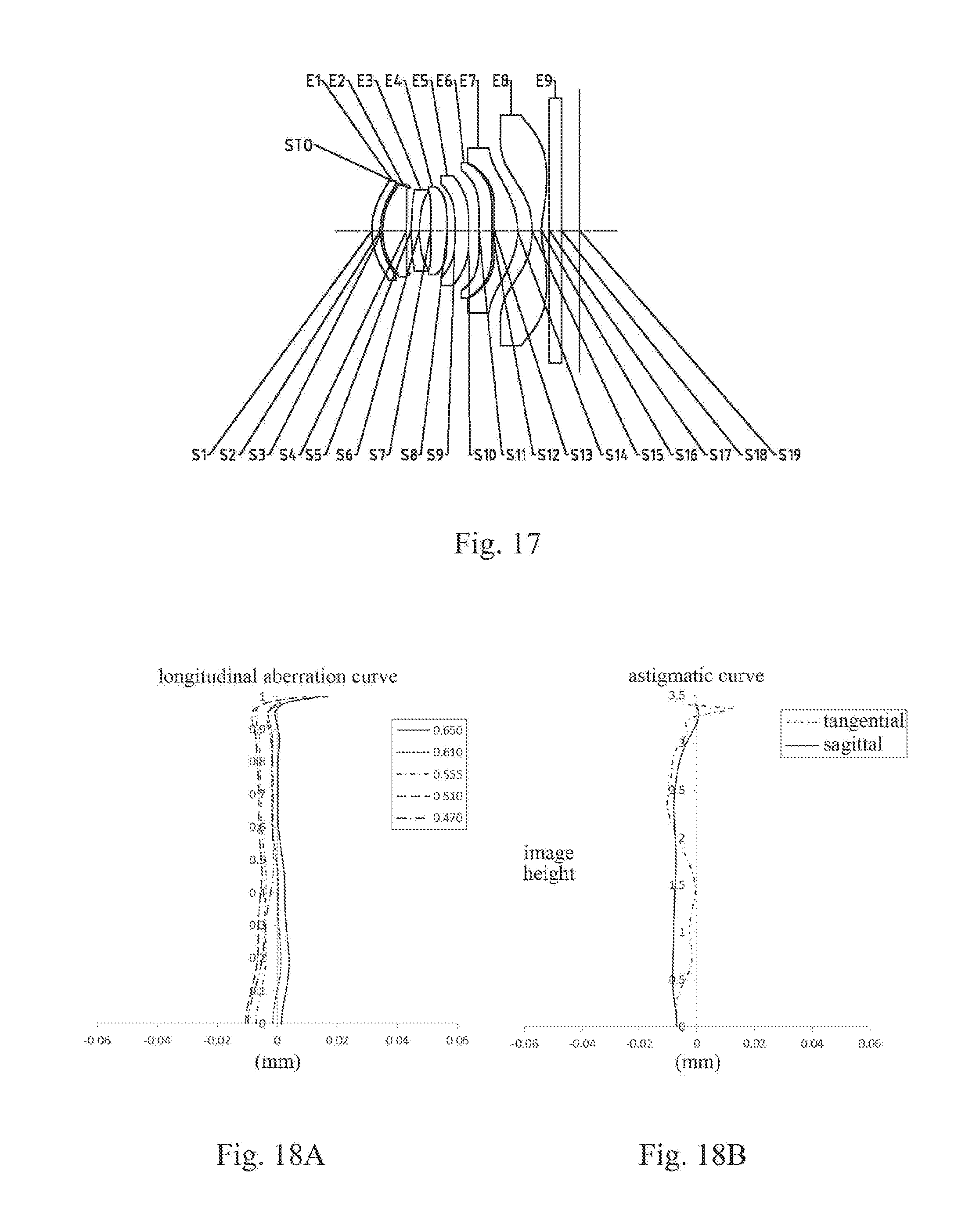
D00014

D00015

D00016
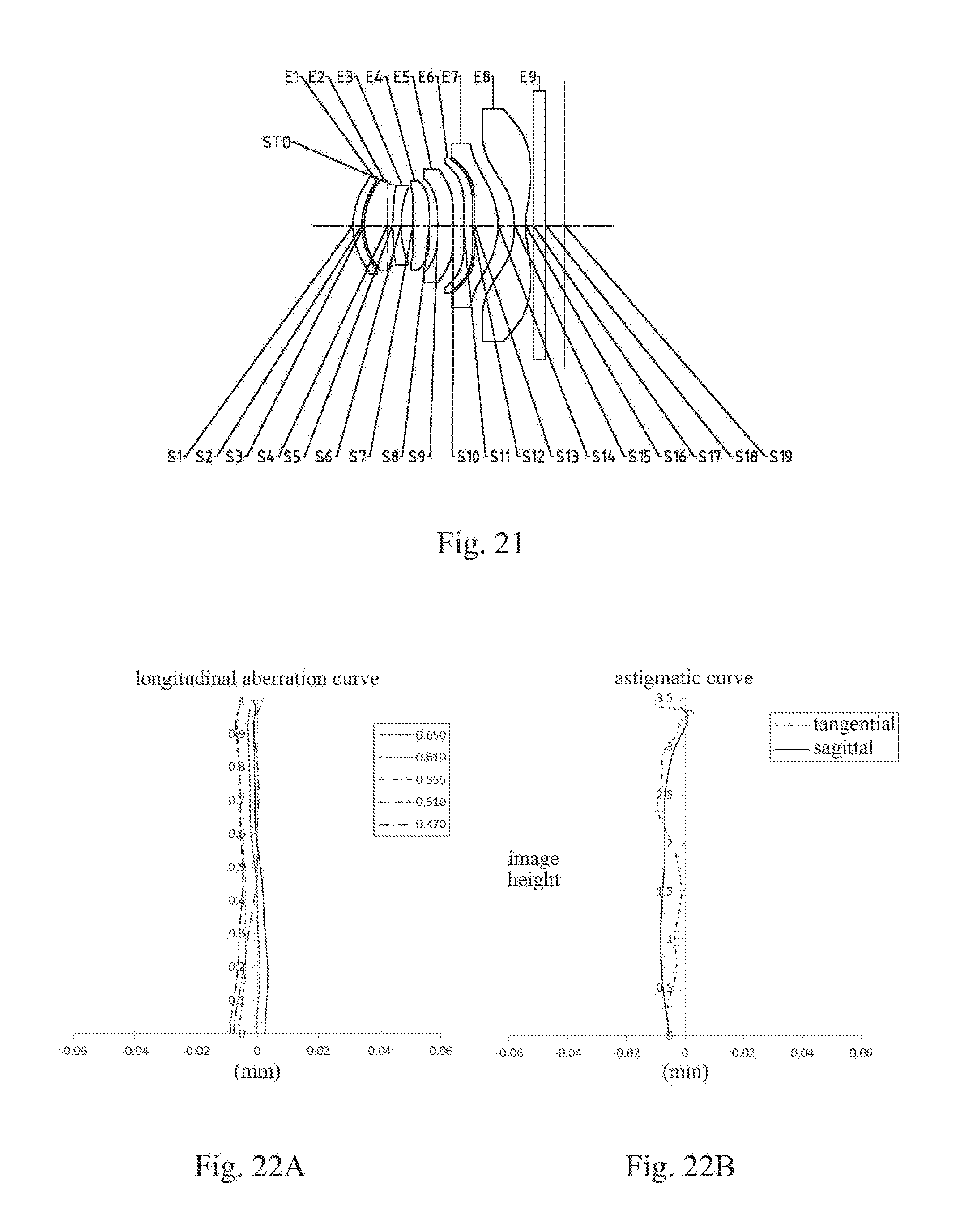
D00017
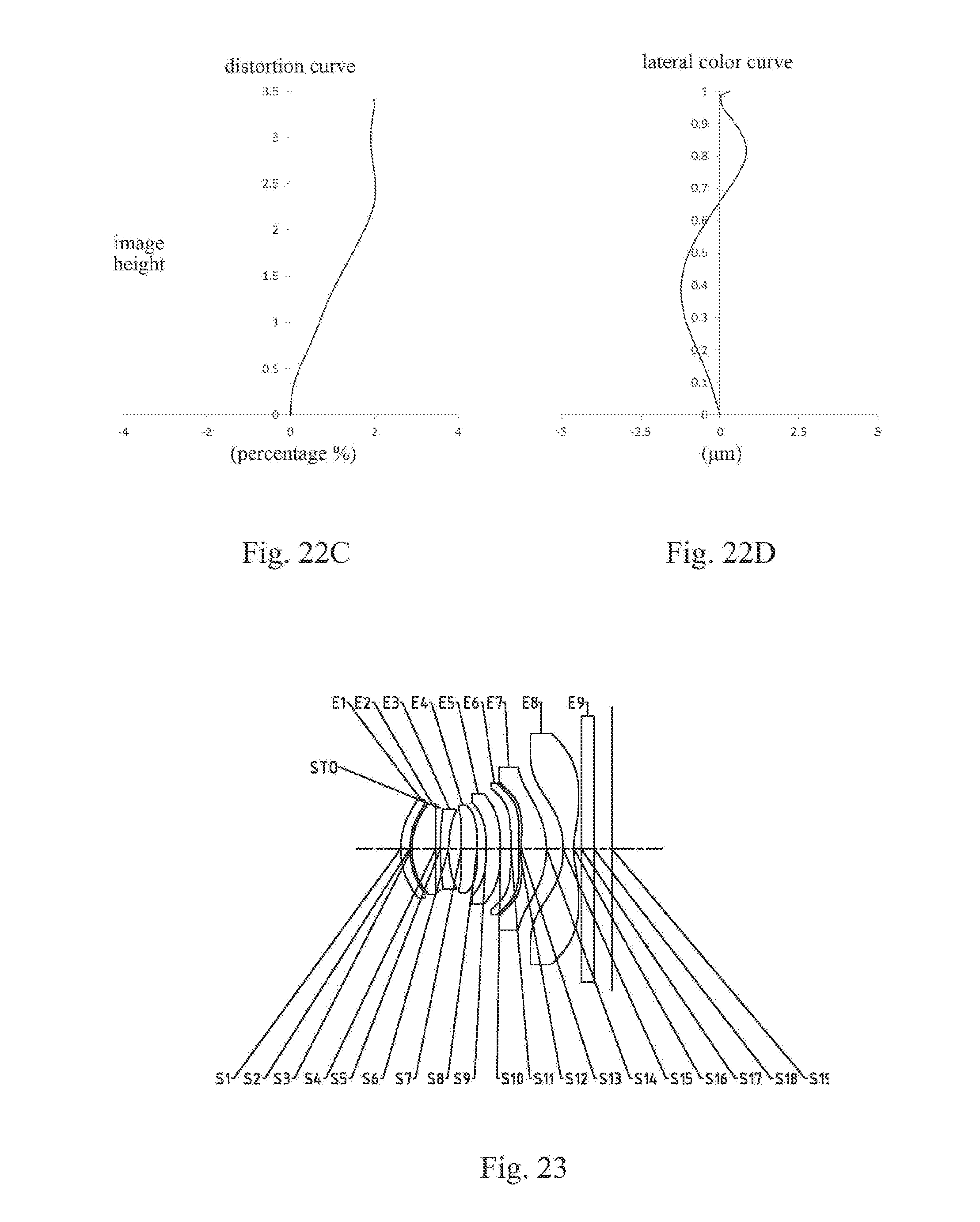
D00018
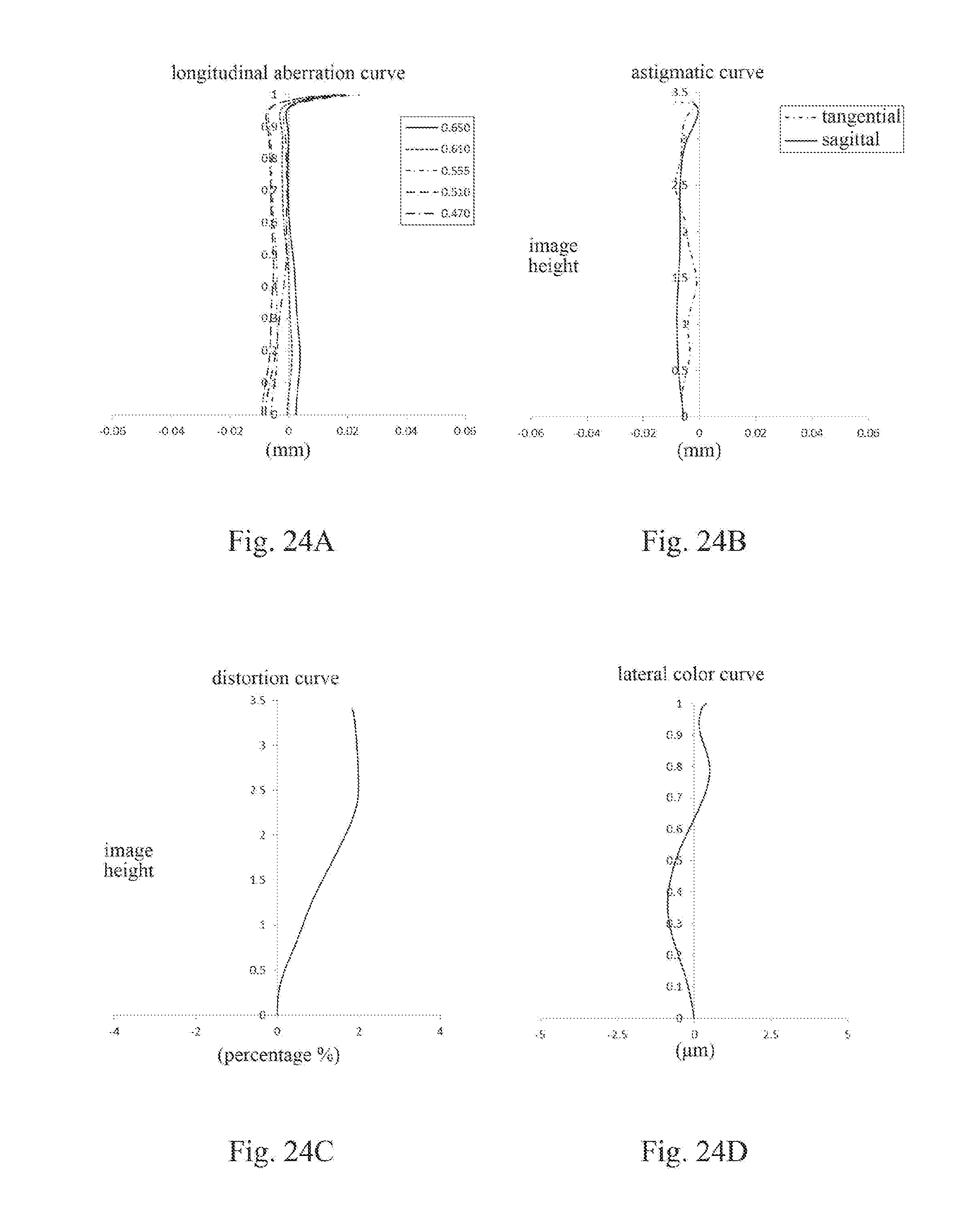
D00019

D00020
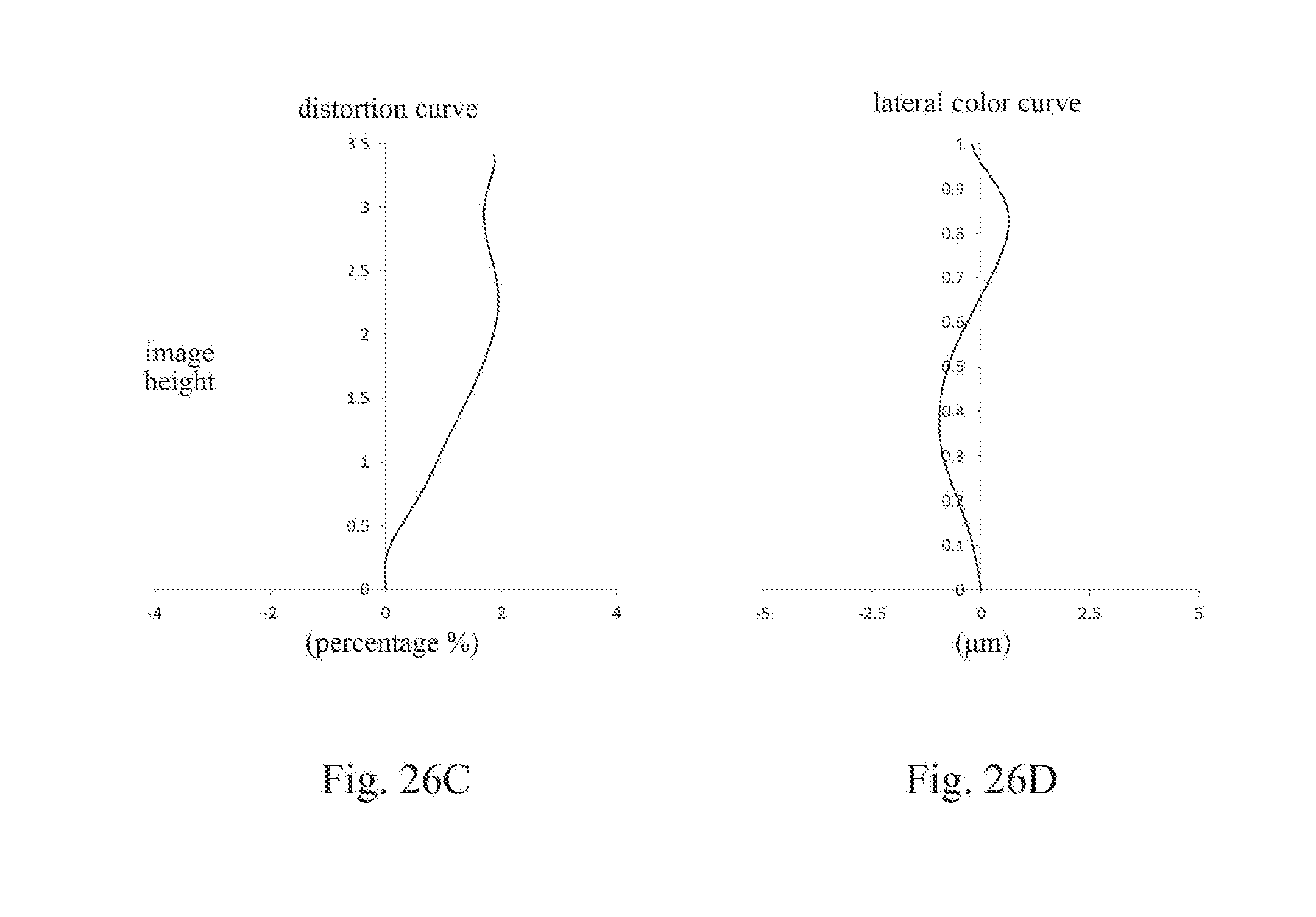

XML
uspto.report is an independent third-party trademark research tool that is not affiliated, endorsed, or sponsored by the United States Patent and Trademark Office (USPTO) or any other governmental organization. The information provided by uspto.report is based on publicly available data at the time of writing and is intended for informational purposes only.
While we strive to provide accurate and up-to-date information, we do not guarantee the accuracy, completeness, reliability, or suitability of the information displayed on this site. The use of this site is at your own risk. Any reliance you place on such information is therefore strictly at your own risk.
All official trademark data, including owner information, should be verified by visiting the official USPTO website at www.uspto.gov. This site is not intended to replace professional legal advice and should not be used as a substitute for consulting with a legal professional who is knowledgeable about trademark law.