Fiber Optic Cassette, System, And Method
Ott; Michael James ; et al.
U.S. patent application number 15/958603 was filed with the patent office on 2019-04-25 for fiber optic cassette, system, and method. The applicant listed for this patent is CommScope Technologies LLC. Invention is credited to David Patrick Murray, Michael James Ott, Patrick J. Thompson.
| Application Number | 20190121047 15/958603 |
| Document ID | / |
| Family ID | 48042127 |
| Filed Date | 2019-04-25 |


View All Diagrams
| United States Patent Application | 20190121047 |
| Kind Code | A1 |
| Ott; Michael James ; et al. | April 25, 2019 |
FIBER OPTIC CASSETTE, SYSTEM, AND METHOD
Abstract
A fiber optic cassette including a body defining a front and an opposite rear and an enclosed interior. A cable entry location is defined in the body for a cable to enter the interior of the cassette. The cable which enters at the cable entry location is attached to the cassette body and the fibers are extended into the cassette body and form terminations at connectors. The connectors are connected to adapters located at the front of the cassette. A front side of the adapters defines termination locations for cables to be connected to the fibers connected at the rear of the adapters. A cable including a jacket, a strength member, and fibers enters the cassette. The strength member is crimped to a crimp tube and is mounted to the cassette body, allowing the fibers to extend past the crimp tube into the interior of the cassette body. A strain relief boot is provided at the cable entry location.
| Inventors: | Ott; Michael James; (Hudson, WI) ; Murray; David Patrick; (Bishopston, GB) ; Thompson; Patrick J.; (Prior Lake, MN) | ||||||||||
| Applicant: |
|
||||||||||
|---|---|---|---|---|---|---|---|---|---|---|---|
| Family ID: | 48042127 | ||||||||||
| Appl. No.: | 15/958603 | ||||||||||
| Filed: | April 20, 2018 |
Related U.S. Patent Documents
| Application Number | Filing Date | Patent Number | ||
|---|---|---|---|---|
| 15392672 | Dec 28, 2016 | 9952400 | ||
| 15958603 | ||||
| 13645634 | Oct 5, 2012 | 9535229 | ||
| 15392672 | ||||
| 61544987 | Oct 7, 2011 | |||
| Current U.S. Class: | 1/1 |
| Current CPC Class: | G02B 6/443 20130101; G02B 6/3897 20130101; G02B 6/4457 20130101; G02B 6/4471 20130101; G02B 6/4453 20130101 |
| International Class: | G02B 6/44 20060101 G02B006/44; G02B 6/38 20060101 G02B006/38 |
Claims
1. A fiber optic cassette comprising: a body defining a front and an opposite rear and an enclosed interior; a cable entry location defined in the body for a cable to enter the interior of the cassette, wherein a cable that enters at the cable entry location is attached to the cassette body and fibers are extended into the cassette body and form terminations at connectors; wherein the connectors are connected to adapters located at the front of the cassette; wherein a front side of the adapters define termination locations for cables to be connected to the fibers connected at the rear of the adapters wherein the cable includes a jacket, a strength member, and fibers, wherein the strength member is crimped to a crimp tube and is mounted to the cassette body, allowing the fibers to extend past the crimp tube into the interior of the cassette body, and wherein a strain relief boot is provided at the cable entry location.
2. The cassette of claim 1, wherein the cable entry location is located at the rear of the cassette body opposite to the front.
3. The cassette of claim 1, wherein the cassette body defines a top surface and a bottom surface which define major sides of the cassette body and extend between the front and the rear, wherein the adapters along the front are arranged linearly and extend in a longitudinal direction parallel to the major surfaces defined by the top and the bottom of the cassette body.
4. The cassette of claim 3, wherein the cable at the cable entry location extends parallel to the longitudinal direction before entry into the cassette body.
5. The cassette of claim 1, further comprising cable radius limiters which provide cable management of the fibers extending from the cable entry location to the connectors at the rear of the adapters.
6. The cassette of claim 1, wherein the adapters are in the form of an adapter block with a plurality of adapters and include a front end, a rear end, and internal structures which allow mating with fiber optic connectors at the front end.
7. The cassette of claim 6, wherein each of the plurality of adapters are configured to receive SC format fiber optic connectors at the front end.
8. The cassette of claim 6, wherein each of the plurality of adapters are configured to receive LC format fiber optic connectors at the front end.
9. The cassette of claim 6, wherein the adapter block is removable from a remainder of the cassette.
10. The cassette of claim 1, wherein a rear of the adapter block defines a rear clip which retains a split sleeve and a hub and ferrule of a connector which terminates an interior fiber.
11. The cassette of claim 1, wherein the rear end of the adapter block defines an opening for receipt of an SC or LC style connector.
12. The cassette of claim 1, wherein the cassette can be utilized in a chassis which includes a stationary mount relative to the chassis, or the cassette can be movably mounted, such as in a variety of sliding movements to allow access to a selected cassette, thereby improving access to a selected front connector attached to the cassette.
13. A fiber optic cassette comprising: a body defining a front and an opposite rear and an enclosed interior, the body further defining a top surface and a bottom surface which define major sides of the cassette body and extend between the front and the rear; a cable entry location defined in the body for a cable to enter the interior of the cassette, wherein a cable that enters at the cable entry location is coupled to the cassette body and fibers are extended into the cassette body and form terminations at first connectors; wherein the first connectors are connected to a rear side of adapters of an adapter block located at the front of the cassette, each of the first connectors including a hub and ferrule and a split sleeve; wherein a front side of the adapters define termination locations for cables to be connected to the fibers connected at the rear side of the adapters, the termination locations configured to receive second fiber optic connectors having a different configuration than the first connectors; and wherein the adapters along the front of the cassette body are arranged linearly and extend in a longitudinal direction parallel to the major surfaces defined by the top and the bottom of the cassette body.
14. The cassette of claim 13, wherein each of the plurality of adapters are configured to receive LC format fiber optic connectors at the front side.
15. The cassette of claim 13, wherein each of the plurality of adapters are configured to receive SC format fiber optic connectors at the front side.
16. The cassette of claim 13, wherein the cable entry location is located at the rear of the cassette body opposite to the front.
17. The cassette of claim 13, wherein the adapter block is removable from a remainder of the cassette.
18. The cassette of claim 13, wherein the cable at the cable entry location extends parallel to the longitudinal direction before entry into the cassette body.
19. The cassette of claim 13, further comprising cable radius limiters which provide cable management of the fibers extending from the cable entry location to the first connectors at the rear side of the adapters.
20. The cassette of claim 13, wherein the cassette can be utilized in a chassis which includes a stationary mount relative to the chassis, or the cassette can be movably mounted, such as in a variety of sliding movements to allow access to a selected cassette, thereby improving access to a selected second fiber optic connector attached to the cassette.
Description
CROSS REFERENCE TO RELATED APPLICATION
[0001] This application is a continuation of U.S. patent application Ser. No. 15/392,672, filed Dec. 28, 2016; which is a continuation of U.S. patent application Ser. No. 13/645,634, filed Oct. 5, 2012, now U.S. Pat. No. 9,535,229; which claims the benefit of U.S. Provisional Patent Application Ser. No. 61/544,987, filed Oct. 7, 2011, which applications are hereby incorporated by reference in their entireties.
BACKGROUND OF THE INVENTION
[0002] As demand for telecommunications increases, fiber optic networks are being extended in more and more areas. Management of the cables, ease of installation, and case of accessibility for later management are important concerns. As a result, there is a need for fiber optic devices and methods which address these and other concerns.
SUMMARY
[0003] An aspect of the present disclosure relates to a fiber optic cassette including a body defining a front and an opposite rear and an enclosed interior. A cable entry location is defined in the body for a cable to enter the interior of the cassette. The cable which enters at the cable entry location is attached to the cassette body and the fibers are extended into the cassette body and form terminations at connectors. The connectors are connected to adapters located at the front of the cassette. A front side of the adapters defines termination locations for cables to be connected to the fibers connected at the rear of the adapters.
[0004] One aspect of the invention relates to providing a cable including a jacket, a strength member. The strength member and the jacket are crimped to a crimp tube and is mounted to the cassette body, allowing the fibers to extend past the crimped tube into the interior of the cassette body. A strain relief boot is provided at the cable entry location.
[0005] In one embodiment, the cable entry location is located at the rear of the cassette body opposite to the front. In one embodiment, the cassette body defines a top surface and a bottom surface which define major sides of the cassette body and extend between the front and the rear. The adapters along the front are arranged linearly in one embodiment and extend in a longitudinal direction parallel to the major surfaces defined by the top and the bottom of the cassette body. The cassette can be oriented in any position, so that the top and bottom sides can be reversed, or positioned vertically, or at some other orientation.
[0006] In one embodiment, the cable at the cable entry location extends parallel to the longitudinal direction before entry into the cassette body.
[0007] Disposed within the cassette body are cable radius limiters which provide cable management of the fibers extending from the cable entry location to the connectors at the rear of the adapters.
[0008] In one embodiment, an adapter block with a plurality of adapters is formed and includes a front end, a rear end, and internal structures which allow mating with fiber optic connectors at the front end, such as SC or LC style connectors. The adapter block may be removable from a remainder of the cassette.
[0009] In one embodiment, a rear of the adapter block defines a rear clip which retains a split sleeve and a hub and ferrule of a connector which terminates an interior fiber. In another embodiment, the rear end of the adapter block defines an opening for receipt of an SC or LC style connector.
[0010] The cassette can be utilized in a chassis which includes a stationary mount relative to the chassis, or the cassette can be movably mounted, such as in a variety of sliding movements to allow access to a selected cassette, thereby improving access to a selected front connector attached to the cassette.
BRIEF DESCRIPTION OF THE DRAWINGS
[0011] FIG. 1 is a perspective view of a first embodiment of a fiber optic cassette in accordance with the present invention;
[0012] FIG. 2 is a further perspective view of FIG. 1 with a portion of the body removed to expose an interior of the cassette.
[0013] FIG. 3 is a top view of the cassette view of FIG. 2;
[0014] FIG. 4 is a schematic view of a portion of a fiber optic cable;
[0015] FIG. 5 is a schematic view of a crimp tube and crimp ring used for crimping to a cable of FIG. 4.
[0016] FIG. 6 is an exploded view showing a rear of the adapter block including a front portion for mating with an SC connector, and a rear portion which mates with a rear connector including a hub and ferrule.
[0017] FIG. 7 shows a perspective view of the adapter block of the cassette of FIG. 1.
[0018] FIG. 8 shows an example cassette like the cassette of FIG. 1, showing example cabling extending from the input cable to the rear connectors of the adapter block.
[0019] FIG. 9 shows a second embodiment of a fiber optic cassette for receipt of LC connectors in a front of the adapter block.
[0020] FIG. 10 shows a third embodiment of a fiber optic cassette in accordance with the present invention without the front adapter block.
[0021] FIG. 11 shows a further perspective view of the cassette of FIG. 10, with portions of the housing removed.
[0022] FIG. 12 is a top view of the cassette of FIG. 11.
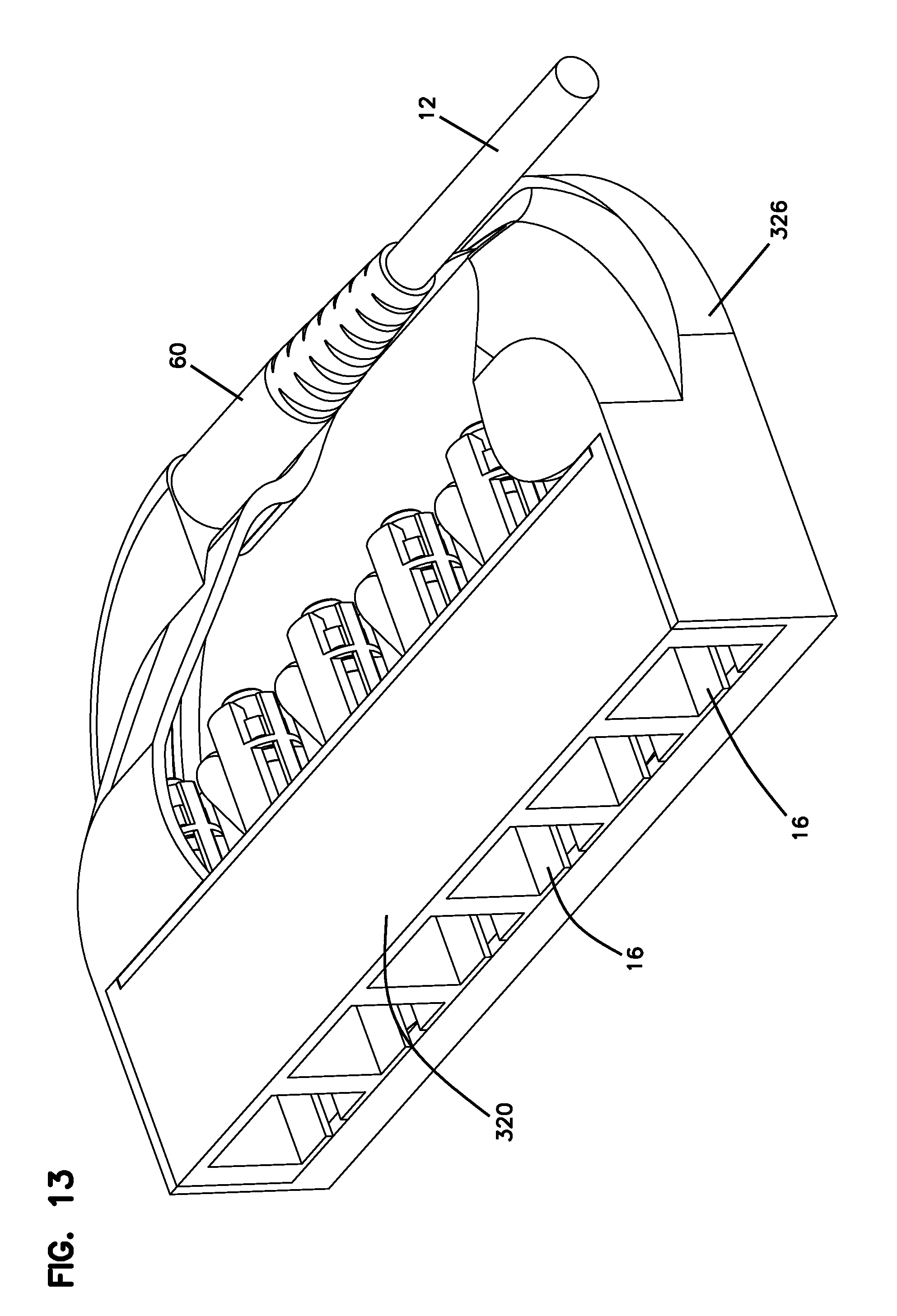
[0023] FIG. 13 shows a fourth embodiment of a fiber optic cassette with portions of the housing removed.
[0024] FIG. 14 shows a further perspective view of the cassette of FIG. 13;
[0025] FIG. 15 shows the cassette of FIG. 13 in exploded view with the adapter block separate from a remainder of the cassette housing;
[0026] FIG. 16 shows an exploded view of the adapter block with the split sleeve and the rear connector removed from the adapter block.
[0027] FIG. 17 is an enlarged view a portion of the view of FIG. 16.
[0028] FIG. 18 is a cross-sectional view through one of the adapter ports of the cassette of FIG. 13;
[0029] FIG. 19 is a cross-sectional perspective view of the rear portion of the housing of the cassette of FIG. 13;
[0030] FIG. 20 is a fifth embodiment of a fiber optic cassette in accordance with the present invention, showing front ports sized for LC connectors, and also showing the use of attenuators in some of the ports.
[0031] FIG. 21 is a view of the cassette of FIG. 20, with portions of the housing of the cassette removed;
[0032] FIG. 22 is an opposite side view of the cassette of FIG. 20, with a circuit board shown removed from the housing.
[0033] FIG. 23 is a first side view of the cassette of FIG. 20.
[0034] FIG. 24 is a second view of the cassette of FIG. 20.
[0035] FIG. 25 is a further side view of the cassette of FIG. 20 with portions of the housing removed;
[0036] FIG. 26 is a front view of the cassette of FIG. 20;
[0037] FIG. 27 is a further side view of the cassette of FIG. 20.
[0038] FIG. 28 shows a cassette mounted for sliding movement relative to a chassis.
[0039] FIG. 29 shows a cassette mounted in a housing.
[0040] FIG. 30 shows another view of the cassette and housing of FIG. 29 with portions of the housing removed.
[0041] FIG. 31 shows the housing of FIGS. 29 and 30 mounted vertically and horizontally in different portions of the chassis.
[0042] FIG. 32 shows a cassette mounted on another housing.
[0043] FIG. 33 shows the housing of FIG. 32 mounted in a chassis.
[0044] FIG. 34 shows a cassette mounted on another housing which is slidably mounted relative to a chassis.
[0045] FIGS. 35 and 36 show further views of the chassis of FIG. 34.
[0046] FIG. 37 shows two cassettes mounted to a spool for storage of one or more input cables.
[0047] FIG. 38 shows in cross-section an example adapter holding a media reading interface.
DETAILED DESCRIPTION
[0048] In FIGS. 1-8, a first fiber optic cassette 10 is shown including a first cable 12 connected to adapters or an adapter block 14 for receipt of connectors, such as LC or SC connectors at front ports 16. Cassette 10 has a single cable 12 which includes multiple fibers 20 which terminate at a distal connector 22, such as an MPO style connector. Cable 12 can be a variety of lengths such as one to 3 feet up to 50 to 100 feet, or more.
[0049] Cassette 10 includes a body 26 defining a front 28, a rear 30 and an interior 32. Body 26 further includes a top 34, a bottom 36, and sides 38, 40.
[0050] Cassette body 26 defines a cable entry location 44 which in the illustrated embodiment is along rear 30. In the illustrated embodiment, cable 12 includes an outer jacket 50 and inner strength member 52 around inner fibers 20. Fibers 20 extend past an end of jacket 50, and an end of strength member 52, and into interior 32 for connection with the front connectors at adapters 14.
[0051] As shown, cable 12 includes a boot 60 to provide strain relief at cable entry location 44. Cable 12 can flex away from cassette body 26 in the direction of arrow A, and is protected from excessive bending by boot 60. Entry 44 is located close to corner 42, so that boot 60 and cable 12 is partially protected at entry 44 by being able to reside in a rear channel 46.
[0052] Adapters 14 are arranged linearly and positioned along longitudinal axis 62. Cable 12 at cable entry location 44 extends parallel to the longitudinal axis 62, although some bending is permitted relative to the longitudinal axis 62.
[0053] In general, cassette 10 includes top 34 and bottom 36 which are generally parallel to each other and define the major surfaces of cassette body 26. Sides 38, 40, front 28, and rear 30 define the minor sides of cassette body 26. The cassette can be oriented in any position, so that the top and bottom surfaces can be reversed, or positioned vertically, or at some other orientation.
[0054] As will be described below, multiple rows of adapters 14 can be provided with cassette 10. See FIG. 32. In the illustrated embodiment, adapters 14 are sized to receive front SC connectors. LC connectors can be used with appropriate sized adapters. See FIGS. 9, 20, and 32.
[0055] Cable 12 is connected to cable entry location 44 with a crimp tube 70 and a crimp ring 72 which crimps jacket 50 and strength member 52 to crimp tube 70. A small pocket 76 captures crimp tube 70 for retention with cassette body 26. Pocket captures hex end 78 of crimp tube 70 to retain cable 12 with cassette body 26.
[0056] Disposed within interior 32 of cassette body 26 are a plurality of radius limiters 80 which provide cable bend radius protection for the fibers disposed within interior 32. Cable radius limiters 80 can be in the form of discrete interior structures, and/or curved exterior surfaces which form around the front 28, rear 30, and sides 38, 40.
[0057] In the illustrated embodiment, the adapters 14 are formed in a block construction 90 having a front end 92, and an opposite rear end 94. Front end 92 includes a profile for receiving SC connectors 108. Front end 92 includes SC clips 96 for clipping to an SC connector. Adapter block 90 also includes a rear clip 98 which clips to a hub and ferrule 100 (hub 104 mounted to ferrule 106) which terminates each fiber 20 exposed within interior 32 of cassette 10. Hub and ferrule 100 form a rear connector. A split sleeve 102 is also provided for ferrule alignment between hub and ferrule 100 (rear connector) and the ferrule of the front SC connector 108.
[0058] As shown in FIG. 8, fibers 20 are provided with excess length between crimp tube 70, and the rear connector defined by the termination at hub and ferrule 100. Severe bending of the fibers is to be avoided. In the illustrated embodiment, the small size of the cassette 10 requires that some fibers 20 reverse direction via limiters 80.
[0059] Referring now to FIG. 9, cassette 110 is constructed in a similar manner as cassette 100 except that the adapters 114 are sized to receive LC connectors at front 128. The hub and ferrule is made correspondingly smaller to accommodate the LC front connectors. Adapters 114 are preferably formed as a block 120.
[0060] In FIGS. 1-9, blocks 90, 120 are snap fit or otherwise attached to a rest of body 26. A cover 48 covers a rear area behind blocks 90, 120. The cassettes 10, 110 can be sealed or they can be openable, so as to allow repair, or cleaning of the inner hub and ferrule 100. In some cases, blocks 90, 120 can be snap fit to a rest of the housing 26 for ease of assembly. Blocks 90, 120 can also preferably be removed from a rest of the cassette 10, 110 to allow for cleaning of the inner connector. The inner fiber slack allows for blocks 90, 120 to be pulled a short distance away from the rest of the cassette 10, 110.
[0061] FIGS. 10-12 show a third embodiment of a fiber optic cassette in accordance with the present invention without the front adapter block. Front clips 220 are used to clip to the adapter blocks 90, 120, and engage projecting posts on the blocks.
[0062] Another embodiment of a fiber optic cassette 310 is shown in FIGS. 13-19. Cassette 310 includes a cable 12, a boot 60 and a cable entry location 344 in a similar location as cassettes 10, 110, 210. Cassette 310 includes a removable adapter block 320, separatable from the rest of body 326. Once removed, module 320 allows rear hub and ferrule 100 to be removed in a similar manner as in cassettes 10, 110, 210. Rear clip 98 includes two clip members 330 which clip onto hub and ferrule 100. To release, tabs 332 are pressed together which causes an outward pivot of clip members 330 about pivot members 334, thereby allowing removal of hub and ferrule 100 for cleaning. Split sleeve 102 may be retained on ferrule 106 during the removal process, and would need to be removed to clean the ferrule tip.
[0063] Cassette 310 also includes a pocket 338 for slack storage of fibers. Pocket 338 is formed with rounded outer surfaces 338 in body 326, and rounded outer surfaces 350 in adapter block 320. Tabs 360 help facilitate positioning of the fiber storage loops in pocket 338, during assembly and later removal of block 320, by directing the loops downward.
[0064] Referring now to FIGS. 20-27, a further alternative embodiment of a cassette 410 is shown. One difference between the cassette 310 of FIGS. 13-19 and cassette 410 is that an interior of the adapter blocks 420 are sized to receive traditional connectors such as SC or LC. In the example embodiment, the adapters are sized to receive LC connectors 408. In this embodiment of a fiber optic cassette, front ports 416 are sized for LC connectors, and show the use of attenuators 450 (with dust caps 460) in some of the ports 416.
[0065] Referring now to FIG. 28, cassette 10 is shown mounted in a chassis for relative movement to the chassis along a sliding direction for access. For comparison, cassette 10 includes a single input cable which connects to a rear MPO panel 480. Similar high-density distribution frames or blocks are described in U.S. Pat. No. 6,591,051, the disclosure of which is incorporated by reference. It should be noted that the cassettes described herein may be used in a sliding packs in a telecommunications rack such as that described in U.S. Pat. No. 6,591,051, incorporated herein by reference in its entirety, or in other drawers and fixtures. Sliding adapter packs 150 such as shown in FIG. 28 are shown with a plurality of individual fibers extending to a fanout 430 which then has a cable 450 that leads to MPO panel 480. Cassettes 10 allow for only single cable 12 to be handled, saving space and installation time.
[0066] Referring now to FIGS. 29-31, cassette 10 is shown mounted to a housing 500, wherein the housing is received in a chassis 530. FIG. 31 shows the housing 500 of FIGS. 29 and 30 mounted vertically and horizontally in different portions of the chassis 530. Preferably, housing 500 is slideably movable to access a selected cassette 10.
[0067] Referring now to FIGS. 32 and 33, an alternative embodiment of a cassette 610 is mounted to a further housing 600 which is received in a chassis 630. Cassette 610 includes two rows of front adapters sized for LC connectors.
[0068] Referring now to FIGS. 34-36, cassettes 110 are shown mounted to a horizontal tray 700 which is slideably received in a chassis 730.
[0069] FIG. 37 shows two cassettes 810 mounted on opposite sides of a spool 820 for storage of the input cable. Together the cassettes 810 and spool 820 form a self contained termination and slack storage unit that can be mounted to a rack, frame, cabinet, drawer, fiber trough, or other device.
[0070] In one embodiment, cassette 10 generally has a length of 3 to 4 inches (parallel to the longitudinal direction 62), a width of 2 to 3 inches (front to back), and a height of approximately 1/2 inch. More preferably, the length is 3 to 31/2 inches, the width is 2 to 21/2 inches, and the height is 1/2 inch. The height can vary as needed, such as to accommodate multiple rows of adapters. With such a construction, it is preferred that the cable enter at the rear of the housing with a strain relief boot and crimp parallel to the front, and that the internal cables include managed slack such as with curved internal surfaces in order to avoid going below the minimum bend radius.
[0071] In accordance with some aspects, certain types of adapters 900 may be configured to collect physical layer information from one or more fiber optic connectors 920 received thereat. For example, as shown in FIG. 38, certain types of adapters 900 may include a body 1000 configured to hold one or more media reading interfaces 1020 that are configured to engage memory contacts on the fiber optic connectors 920. One or more media reading interfaces 1020 may be positioned in the adapter body 1000. In certain implementations, the adapter body 1000 defines slots 1010 extending between an exterior of the adapter body 1000 and an internal passage in which the ferrules of the connectors 920 are received.
[0072] Certain types of media reading interfaces 1020 include one or more contact members 1021 that are positioned in the slots 1010. As shown in FIG. 38, a portion of each contact member 1021 extends into a respective one of the passages to engage memory contacts on a fiber optic connector 920. Another portion of each contact member 1021 also extends out of the slot 1010 to contact a circuit board 1030. Portions of the cassette may define conductive paths that are configured to connect the media reading interfaces 1020 of the adapter 900 with a master circuit board. The master circuit board may include or connect (e.g., over a network) to a processing unit that is configured to manage physical layer information obtained by the media reading interfaces. See also cassette 410 of FIGS. 20-27.
[0073] Example adapters having media reading interfaces and example fiber optic connectors having suitable memory storage and memory contacts are shown in U.S. Pat. No. 8,690,593, the disclosure of which is hereby incorporated by reference.
[0074] In addition to the various uses and applications of the described cassettes, the cassettes can be used to terminate the fibers of a multi-fiber FOT cable, such as a 144 fiber cable, to make installation of the terminated cables easier and faster. Also, the cassette can be associated with a cable spool such as disclosed in U.S. Pat. Nos. 9,063,316 or 8,422,847, the disclosures of which are hereby incorporated by reference.
[0075] One advantage of the disclosed cassettes is that handling in the field of individual connectors is eliminated or MPO connectors and fanouts with upjackets are eliminated.
* * * * *
D00000
D00001
D00002
D00003
D00004
D00005
D00006
D00007
D00008
D00009
D00010
D00011
D00012
D00013

D00014

D00015

D00016

D00017

D00018

D00019

D00020

D00021

D00022

D00023

D00024

D00025

D00026

D00027

D00028

D00029

D00030

D00031

D00032

D00033

D00034

XML
uspto.report is an independent third-party trademark research tool that is not affiliated, endorsed, or sponsored by the United States Patent and Trademark Office (USPTO) or any other governmental organization. The information provided by uspto.report is based on publicly available data at the time of writing and is intended for informational purposes only.
While we strive to provide accurate and up-to-date information, we do not guarantee the accuracy, completeness, reliability, or suitability of the information displayed on this site. The use of this site is at your own risk. Any reliance you place on such information is therefore strictly at your own risk.
All official trademark data, including owner information, should be verified by visiting the official USPTO website at www.uspto.gov. This site is not intended to replace professional legal advice and should not be used as a substitute for consulting with a legal professional who is knowledgeable about trademark law.