Natural Gas Liquefaction by a High Pressure Expansion Process using Multiple Turboexpander Compressors
Pierre, JR.; Fritz ; et al.
U.S. patent application number 16/144581 was filed with the patent office on 2019-04-25 for natural gas liquefaction by a high pressure expansion process using multiple turboexpander compressors. The applicant listed for this patent is Fritz Pierre, JR., O. Angus Sites, William N. Yunker. Invention is credited to Fritz Pierre, JR., O. Angus Sites, William N. Yunker.
| Application Number | 20190120548 16/144581 |
| Document ID | / |
| Family ID | 63963421 |
| Filed Date | 2019-04-25 |


| United States Patent Application | 20190120548 |
| Kind Code | A1 |
| Pierre, JR.; Fritz ; et al. | April 25, 2019 |
Natural Gas Liquefaction by a High Pressure Expansion Process using Multiple Turboexpander Compressors
Abstract
A method and system for liquefying a feed gas stream including natural gas. The feed gas stream is provided at a pressure less than 1,200 psia. A refrigerant stream having a pressure of at least 1,500 psia is cooled and then expanded in a first expander to an intermediate pressure. The first expander is mechanically coupled to a first coupled compressor to together form a first turboexpander-compressor. The refrigerant stream is expanded in a second expander, which is mechanically coupled to a second coupled compressor to together form a second turboexpander-compressor. The refrigerant stream cools the feed gas stream in one or more heat exchangers. Using the second coupled compressor and a first driven compressor, the refrigerant stream is compressed to a discharge pressure within 300 psia of the intermediate pressure. The refrigerant stream is compressed using the first coupled compressor and is further compressed to provide the refrigerant stream.
| Inventors: | Pierre, JR.; Fritz; (Humble, TX) ; Yunker; William N.; (Boling, IL) ; Sites; O. Angus; (Spring, TX) | ||||||||||
| Applicant: |
|
||||||||||
|---|---|---|---|---|---|---|---|---|---|---|---|
| Family ID: | 63963421 | ||||||||||
| Appl. No.: | 16/144581 | ||||||||||
| Filed: | September 27, 2018 |
Related U.S. Patent Documents
| Application Number | Filing Date | Patent Number | ||
|---|---|---|---|---|
| 62576989 | Oct 25, 2017 | |||
| Current U.S. Class: | 1/1 |
| Current CPC Class: | F25J 2220/62 20130101; F25J 2245/90 20130101; F25J 2210/06 20130101; F25J 1/0022 20130101; F25J 1/004 20130101; F25J 2230/20 20130101; F25J 1/0205 20130101; F25J 1/0208 20130101; F25J 1/0045 20130101; F25J 1/005 20130101; F25J 1/0082 20130101; F25J 1/0288 20130101; F25J 1/0042 20130101; F25J 1/0254 20130101; F25J 2230/30 20130101; F25J 2270/16 20130101; F25J 1/0072 20130101; F25J 1/025 20130101 |
| International Class: | F25J 1/00 20060101 F25J001/00; F25J 1/02 20060101 F25J001/02 |
Claims
1. A method for liquefying a feed gas stream comprising natural gas, the method comprising: providing the feed gas stream at a pressure less than 1,200 psia; providing a compressed refrigerant stream with a pressure greater than or equal to 1,500 psia; cooling the compressed refrigerant stream by indirect heat exchange with a cooling medium, thereby producing a compressed, cooled refrigerant stream; expanding the compressed, cooled refrigerant stream in a first expander to an intermediate pressure to further cool the compressed, cooled refrigerant stream, thereby producing a first expanded, cooled refrigerant stream, wherein the first expander is mechanically coupled to a first coupled compressor to together form a first turboexpander-compressor; expanding the first expanded, cooled refrigerant stream in a second expander to further cool the first expanded, cooled refrigerant stream, thereby producing a second expanded, cooled refrigerant stream, wherein the second expander is mechanically coupled to a second coupled compressor to together form a second turboexpander-compressor; passing the second expanded, cooled refrigerant stream through one or more heat exchangers, thereby forming a warm refrigerant stream; passing the feed gas stream through the one or more heat exchangers to cool at least part of the feed gas stream by indirect heat exchange with the second expanded, cooled refrigerant stream, thereby forming a cool feed gas stream; using the second coupled compressor and a first driven compressor, compressing the warm refrigerant stream to a discharge pressure within 300 psia of the intermediate pressure, thereby forming a first compressed refrigerant stream; compressing the first compressed refrigerant stream using the first coupled compressor, thereby forming a second compressed refrigerant stream; and compressing the second compressed refrigerant stream to provide the compressed refrigerant stream.
2. The method of claim 1, further comprising driving the first driven compressor using at least one of a reciprocating engine, a steam turbine, a gas turbine, and a motor.
3. The method of claim 1, wherein cooling the compressed refrigerant stream comprises cooling the compressed refrigerant stream via indirect heat exchange with a cooling medium.
4. The method of claim 1, wherein cooling the compressed refrigerant stream comprises cooling the compressed refrigerant stream by indirect heat exchange with a cooling medium having a temperature lower than ambient conditions.
5. The method of claim 1, further comprising: cooling the warm refrigerant stream by indirect heat exchange with a cooling medium after being compressed in the second coupled compressor and prior to being compressed in the first driven compressor.
6. The method of claim 1, further comprising: cooling the first compressed refrigerant stream prior to being compressed in the first coupled compressor.
7. The method of claim 1, further comprising: cooling the second compressed refrigerant stream via indirect heat exchange with a cooling medium prior to being compressed to provide the compressed refrigerant stream.
8. The method of claim 1, wherein the compressed refrigerant stream has a pressure of approximately 3,000 psia.
9. The method of claim 1, wherein the intermediate pressure is less than 1,500 psia and greater than 1,000 psia.
10. The method of claim 1, wherein compressing the second compressed refrigerant stream is accomplished using a second driven compressor.
11. The method of claim 10, further comprising: driving the second driven compressor using at least one of a reciprocating engine, a steam turbine, a gas turbine, and a motor.
12. The method of claim 10, wherein the first driven compressor and the second driven compressor share a common driver.
13. The method of claim 10, wherein the first driven compressor and the second driven compressor are within a single compressor casing.
14. The method of claim 1, further comprising: using a sub-cooling loop, further cooling the cool feed gas stream to form a sub-cooled feed gas stream.
15. The method of claim 14, further comprising: expanding the sub-cooled feed gas stream to a pressure greater than or equal to 50 psia and less than or equal to 450 psia, to produce an expanded, sub-cooled feed gas stream.
16. The method of claim 14, wherein the sub-cooled feed gas stream is expanded within a hydraulic turbine.
17. The method of claim 14, wherein the sub-cooling loop is a closed loop gas phase refrigeration cycle where nitrogen gas is the refrigerant.
18. The method of claim 14, wherein the sub-cooling loop comprises: withdrawing a portion not to exceed 50% of the expanded, sub-cooled gas stream and reducing its pressure in a pressure reduction valve to a range of about 30 to 300 psia to produce one or more reduced pressure gas streams; and passing the one or more reduced pressure gas streams through the one or more heat exchangers as the sub-cooling refrigerant stream.
19. The method of claim 18, wherein the one or more reduced pressure gas streams are at different pressures from each other.
20. The method of claim 18, wherein the sub-cooling refrigerant stream exiting the one or more heat exchangers is compressed to a pressure approximate to that of the feed gas stream and is cooled by indirect heat exchange with a cooling medium before mixing the sub-cooling refrigerant stream with the feed gas stream.
21. The method of claim 15, wherein at least a portion of the expanded, sub-cooled gas stream is further expanded and then directed to a separation tank from which liquid natural gas is withdrawn and remaining gaseous vapors are withdrawn as a flash gas stream.
22. The method of claim 21, wherein the compressed refrigerant stream comprises boil off gas of the liquid natural gas.
23. The method of claim 1, further comprising: adjusting one or more of a discharge pressure of one or more of the compressors, and an inlet pressure of one or more of the expanders, to thereby maintain a fixed differential pressure between the discharge pressure and the inlet pressure.
24. The method of claim 23, wherein the fixed differential pressure is obtained through control algorithms using one or more of compressor speed of one or more of the compressors, inlet guide vanes of one ore more of the expanders, recycle valves of one or more of the compressors, and bypass valves of one or more of the expanders.
25. The method of claim 23, further comprising: using expander thrust bearing temperature as a limit to protect thrust bearing integrity while maximizing cycle efficiency.
26. A natural gas liquefaction system comprising: a first heat exchanger configured to cool a compressed refrigerant stream by indirect heat exchange with a cooling medium, thereby producing a compressed, cooled refrigerant stream, wherein the compressed refrigerant stream is provided to the first heat exchanger at a pressure of at least 1,500 psia; a first expander configured to expand the compressed, cooled refrigerant stream to an intermediate pressure, to further cool the compressed, cooled refrigerant stream, thereby producing a first expanded, cooled refrigerant stream; a first coupled compressor mechanically coupled to the first expander to together form a first turboexpander-compressor; a second expander configured to expand the first expanded, cooled refrigerant stream to further cool the first expanded, cooled refrigerant stream, thereby producing a second expanded, cooled refrigerant stream; a second coupled compressor mechanically coupled to the second expander to together form a second turboexpander-compressor; one or more heat exchangers arranged to permit the second expanded, cooled refrigerant stream and a feed gas stream to pass therethrough and exchange heat therein through indirect heat exchange, thereby forming a warm refrigerant stream and a cool feed gas stream, wherein the feed gas stream comprises natural gas and is supplied to the one or more heat exchangers at a pressure of less than 1,200 psia; a first driven compressor configured to, along with the second coupled compressor, compress the warm refrigerant stream to a discharge pressure within 300 psia of the intermediate pressure, thereby forming a first compressed refrigerant stream; wherein the first compressed refrigerant stream is further compressed using the first coupled compressor, thereby forming a second compressed refrigerant stream; and wherein the second compressed refrigerant stream is compressed to provide the compressed refrigerant stream.
27. The system of claim 26, further comprising a driving element configured to drive the first driven compressor, wherein the driving element comprises at least one of a reciprocating engine, a steam turbine, a gas turbine, and a motor.
28. The system of claim 26, further comprising: a first cooler configured to cool the compressed refrigerant stream via indirect heat exchange with a cooling medium.
29. The system of claim 28, wherein the cooling medium has a temperature lower than ambient conditions.
30. The system of claim 26, further comprising: a second cooler configured to cool the warm refrigerant stream by indirect heat exchange with a cooling medium after being compressed in the second coupled compressor and prior to being compressed in the first driven compressor; a third cooler configured to cool the first compressed refrigerant stream prior to being compressed in the first coupled compressor; and a fourth cooler configured to cool the second compressed refrigerant stream via indirect heat exchange with a cooling medium prior to being compressed, to thereby provide the compressed refrigerant stream.
31. The system of claim 26, wherein the compressed refrigerant stream has a pressure of approximately 3,000 psia.
32. The system of claim 26, wherein the intermediate pressure is less than 1,500 psia and greater than 1,000 psia.
33. The system of claim 26, further comprising: a second driven compressor configured to compress the second compressed refrigerant stream.
34. The system of claim 33, further comprising: a driving element configured to drive the second driven compressor, wherein the driving element comprises at least one of a reciprocating engine, a steam turbine, a gas turbine, and a motor.
35. The system of claim 33, wherein the first driven compressor and the second driven compressor share a common driver.
36. The system of claim 32, wherein the first driven compressor and the second driven compressor are within a single compressor casing.
37. The system of claim 26, further comprising a sub-cooling loop configured to further cool the cool feed gas stream to form a sub-cooled feed gas stream.
38. The system of claim 37, further comprising: a hydraulic turbine configured to expand the sub-cooled feed gas stream to a pressure greater than or equal to 50 psia and less than or equal to 450 psia, to thereby produce an expanded, sub-cooled feed gas stream.
39. The system of claim 37, wherein the sub-cooling loop is a closed loop gas phase refrigeration cycle where nitrogen gas is the refrigerant.
40. A method for liquefying a feed gas stream comprising natural gas, the method comprising: providing the feed gas stream at a pressure less than 1,200 psia; providing a compressed refrigerant stream with a pressure greater than or equal to 1,500 psia; cooling the compressed refrigerant stream by indirect heat exchange with a first cooling medium, thereby producing a compressed, cooled refrigerant stream; expanding the compressed, cooled refrigerant stream in a first expander to an intermediate pressure to further cool the compressed, cooled refrigerant stream, thereby producing a first expanded, cooled refrigerant stream, wherein the first expander is mechanically coupled to a first coupled compressor to together form a first turboexpander-compressor; expanding the first expanded, cooled refrigerant stream in a second expander to further cool the first expanded, cooled refrigerant stream, thereby producing a second expanded, cooled refrigerant stream, wherein the second expander is mechanically coupled to a second coupled compressor to together form a second turboexpander-compressor; passing the second expanded, cooled refrigerant stream through one or more heat exchangers, thereby forming a warm refrigerant stream; passing the feed gas stream through the one or more heat exchangers to cool at least part of the feed gas stream by indirect heat exchange with the second expanded, cooled refrigerant stream, thereby forming a cool feed gas stream; using a sub-cooling loop, further cooling the cool feed gas stream to form a sub-cooled feed gas stream having a liquid portion; using the second coupled compressor and a first driven compressor, compressing the warm refrigerant stream to a discharge pressure within 300 psia of the intermediate pressure, thereby forming a first compressed refrigerant stream; cooling the warm refrigerant stream by indirect heat exchange with a second cooling medium after being compressed in the second coupled compressor and prior to being compressed in the first driven compressor; cooling the first compressed refrigerant stream via heat exchange with a third cooling medium; compressing the first compressed refrigerant stream using the first coupled compressor, thereby forming a second compressed refrigerant stream; cooling the second compressed refrigerant stream via heat exchange with a fourth cooling medium; and compressing the second compressed refrigerant stream to provide the compressed refrigerant stream.
41. The method of claim 40, wherein at least one of the first cooling medium, the second cooling medium, the third cooling medium, and the fourth cooling medium comprises air or water.
Description
CROSS REFERENCE TO RELATED APPLICATION
[0001] This application claims the priority benefit of U.S. Provisional Application No. 62/576,989, filed Oct. 25, 2017 entitled "Natural Gas Liquefaction by a High Pressure Expansion Process Using Multiple Turboexpander Compressors," the entirety of which is incorporated herein.
BACKGROUND
Field of Disclosure
[0002] The disclosure relates generally to liquefied natural gas (LNG) production. More specifically, the disclosure relates to LNG production at high pressures.
Description of Related Art
[0003] This section is intended to introduce various aspects of the art, which may be associated with the present disclosure. This discussion is intended to provide a framework to facilitate a better understanding of particular aspects of the present disclosure. Accordingly, it should be understood that this section should be read in this light, and not necessarily as an admission of prior art.
[0004] Because of its clean burning qualities and convenience, natural gas has become widely used in recent years. Many sources of natural gas are located in remote areas, which are great distances from any commercial markets for the gas. Sometimes a pipeline is available for transporting produced natural gas to a commercial market. When pipeline transportation is not feasible, produced natural gas is often processed into liquefied natural gas (LNG) for transport to market.
[0005] In the design of an LNG plant, one of the most important considerations is the process for converting the natural gas feed stream into LNG. Currently, the most common liquefaction processes use some form of refrigeration system. Although many refrigeration cycles have been used to liquefy natural gas, the three types most commonly used in LNG plants today are: (1) the "cascade cycle," which uses multiple single component refrigerants in heat exchangers arranged progressively to reduce the temperature of the gas to a liquefaction temperature; (2) the "multi-component refrigeration cycle," which uses a multi-component refrigerant in specially designed exchangers; and (3) the "expander cycle," which expands gas from feed gas pressure to a low pressure with a corresponding reduction in temperature. Most natural gas liquefaction cycles use variations or combinations of these three basic types.
[0006] The refrigerants used in liquefaction processes may comprise a mixture of components such as methane, ethane, propane, butane, and nitrogen in multi-component refrigeration cycles. The refrigerants may also be pure substances such as propane, ethylene, or nitrogen in "cascade cycles." Substantial volumes of these refrigerants with close control of composition are required. Further, such refrigerants may have to be imported and stored, which impose logistics requirements, especially for LNG production in remote locations. Alternatively, some of the components of the refrigerant may be prepared, typically by a distillation process integrated with the liquefaction process.
[0007] The use of gas expanders to provide the feed gas cooling, thereby eliminating or reducing the logistical problems of refrigerant handling, is seen in some instances as having advantages over refrigerant-based cooling. The expander system operates on the principle that the refrigerant gas can be allowed to expand through an expansion turbine, thereby performing work and reducing the temperature of the gas. The low temperature gas is then heat exchanged with the feed gas to provide the refrigeration needed. The power obtained from cooling expansions in gas expanders can be used to supply part of the main compression power used in the refrigeration cycle. The typical expander cycle for making LNG operates at the feed gas pressure, typically under about (1,000 psia). Supplemental cooling is typically needed to fully liquefy the feed gas and this may be provided by additional refrigerant systems, such as secondary cooling and/or sub-cooling loops. For example, U.S. Pat. Nos. 6,412,302 and 5,916,260 present expander cycles which describe the use of nitrogen as refrigerant in the sub-cooling loop.
[0008] Previously proposed expander cycles have all been less efficient thermodynamically, however, than the current natural gas liquefaction cycles based on refrigerant systems. Expander cycles have therefore not offered any installed cost advantage to date, and liquefaction cycles involving refrigerants are still the preferred option for natural gas liquefaction.
[0009] Because expander cycles result in a high recycle gas stream flow rate and high inefficiency for the primary cooling (warm) stage, gas expanders have typically been used to further cool feed gas after it has been pre-cooled to temperatures well below -20.degree. C. using an external refrigerant in a closed cycle, for example. Thus, a common factor in most proposed expander cycles is the requirement for a second, external refrigeration cycle to pre-cool the gas before the gas enters the expander. Such a combined external refrigeration cycle and expander cycle is sometimes referred to as a "hybrid cycle." While such refrigerant-based pre-cooling eliminates a major source of inefficiency in the use of expanders, it significantly reduces the benefits of the expander cycle, namely the elimination of external refrigerants.
[0010] U. S. Patent Application US2009/0217701 introduced the concept of using high pressure within the primary cooling loop to eliminate the need for external refrigerant and improve efficiency, at least comparable to that of refrigerant-based cycles currently in use. The high pressure expander process (HPXP), disclosed in U. S. Patent Application US2009/0217701, is an expander cycle which uses high pressure expanders in a manner distinguishing from other expander cycles. A portion of the feed gas stream may be extracted and used as the refrigerant in either an open loop or closed loop refrigeration cycle to cool the feed gas stream below its critical temperature. Alternatively, a portion of LNG boil-off gas may be extracted and used as the refrigerant in a closed loop refrigeration cycle to cool the feed gas stream below its critical temperature. This refrigeration cycle is referred to as the primary cooling loop. The primary cooling loop is followed by a sub-cooling loop which acts to further cool the feed gas. Within the primary cooling loop, the refrigerant is compressed to a pressure greater than 1,500 psia, or more preferably, to a pressure of approximately 3,000 psia. The refrigerant is then cooled against an ambient cooling medium (air or water) prior to being near isentropically expanded to provide the cold refrigerant needed to liquefy the feed gas.
[0011] FIG. 1 schematically depicts an example of a known HPXP liquefaction system 100, and is similar to one or more systems and processes disclosed in U. S. Patent Application US2009/0217701. In FIG. 1, an expander loop 102 (i.e., an expander cycle) and a sub-cooling loop 104 are used. Feed gas stream 106 enters the HPXP liquefaction process at a pressure less than about 1,200 psia, or less than about 1,100 psia, or less than about 1,000 psia, or less than about 900 psia, or less than about 800 psia, or less than about 700 psia, or less than about 600 psia. Typically, the pressure of feed gas stream 106 will be about 800 psia. Feed gas stream 106 generally comprises natural gas that has been treated to remove contaminants using processes and equipment that are well known in the art.
[0012] In the expander loop 102, a compression unit 108 compresses a refrigerant stream 109 (which may be a treated gas stream) to a pressure greater than or equal to about 1,500 psia, thus providing a compressed refrigerant stream 110. Alternatively, the refrigerant stream 109 may be compressed to a pressure greater than or equal to about 1,600 psia, or greater than or equal to about 1,700 psia, or greater than or equal to about 1,800 psia, or greater than or equal to about 1,900 psia, or greater than or equal to about 2,000 psia, or greater than or equal to about 2,500 psia, or greater than or equal to about 3,000 psia, thus providing compressed refrigerant stream 110. After exiting compression unit 108, compressed refrigerant stream 110 is passed to a cooler 112 where it is cooled by indirect heat exchange with a suitable cooling medium to provide a compressed, cooled refrigerant stream 114. Cooler 112 may be of the type that provides water or air as the cooling medium, although any type of cooler can be used. The temperature of the compressed, cooled refrigerant stream 114 depends on the ambient conditions and the cooling medium used, and is typically from about 35.degree. F. to about 105.degree. F. Compressed, cooled refrigerant stream 114 is then passed to an expander 116 where it is expanded and consequently cooled to form an expanded refrigerant stream 118. Expander 116 is a work-expansion device, such as a gas expander, which produces work that may be extracted and used for compression. Expanded refrigerant stream 118 is passed to a first heat exchanger 120, and provides at least part of the refrigeration duty for first heat exchanger 120. Upon exiting first heat exchanger 120, expanded refrigerant stream 118 is fed to a compression unit 122 for pressurization to form refrigerant stream 109.
[0013] Feed gas stream 106 flows through first heat exchanger 120 where it is cooled, at least in part, by indirect heat exchange with expanded refrigerant stream 118. After exiting first heat exchanger 120, the feed gas stream 106 is passed to a second heat exchanger 124. The principal function of second heat exchanger 124 is to sub-cool the feed gas stream. Thus, in second heat exchanger 124 the feed gas stream 106 is sub-cooled by sub-cooling loop 104 (described below) to produce sub-cooled gas stream 126. Sub-cooled gas stream 126 is then expanded to a lower pressure in an expander 128 to form a liquid fraction and a remaining vapor fraction. Expander 128 may be any pressure reducing device, including, but not limited to a valve, control valve, Joule Thompson valve, Venturi device, liquid expander, hydraulic turbine, and the like. The sub-cooled gas stream 126, which is now at a lower pressure and partially liquefied, is passed to a surge tank 130 where the liquefied fraction 132 is withdrawn from the process as an LNG stream 134, which has a temperature corresponding to the bubble point pressure. The remaining vapor fraction (flash vapor) stream 136 may be used as fuel to power the compressor units.
[0014] In sub-cooling loop 104, an expanded sub-cooling refrigerant stream 138 (preferably comprising nitrogen) is discharged from an expander 140 and drawn through second and first heat exchangers 124, 120. Expanded sub-cooling refrigerant stream 138 is then sent to a compression unit 142 where it is re-compressed to a higher pressure and warmed. After exiting compression unit 142, the re-compressed sub-cooling refrigerant stream 144 is cooled in a cooler 146, which can be of the same type as cooler 112, although any type of cooler may be used. After cooling, the re-compressed sub-cooling refrigerant stream is passed to first heat exchanger 120 where it is further cooled by indirect heat exchange with expanded refrigerant stream 118 and expanded sub-cooling refrigerant stream 138. After exiting first heat exchanger 120, the re-compressed and cooled sub-cooling refrigerant stream is expanded through expander 140 to provide a cooled stream which is then passed through second heat exchanger 124 to sub-cool the portion of the feed gas stream to be finally expanded to produce LNG.
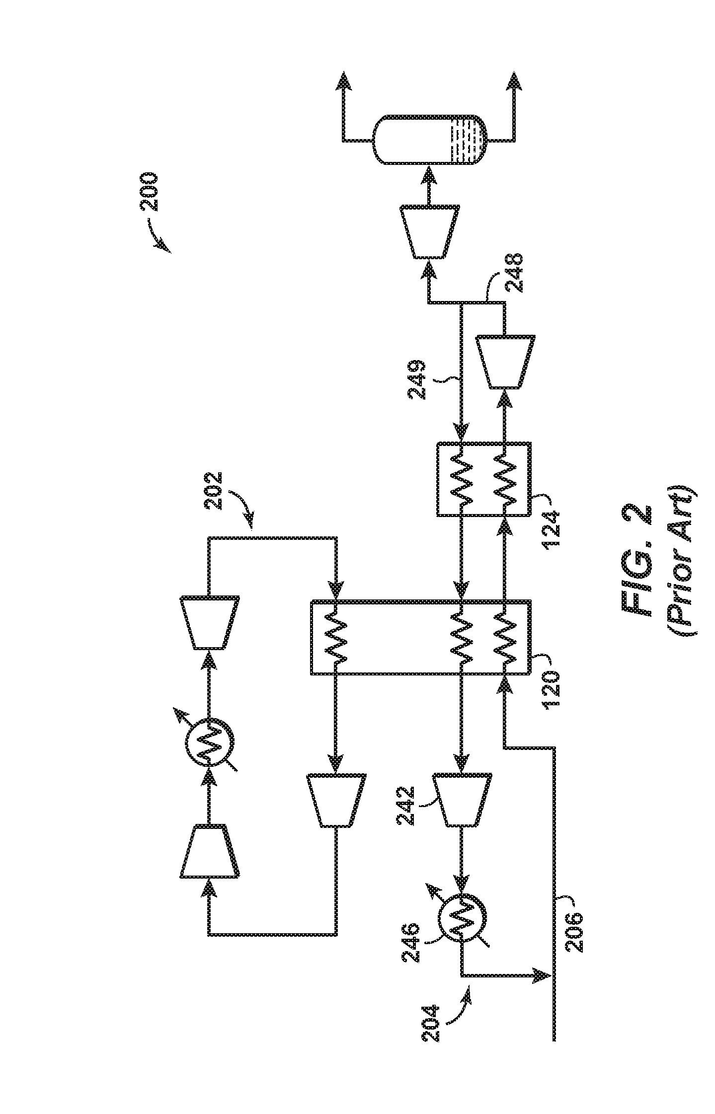
[0015] FIG. 2 is a schematic diagram of another liquefaction system 200 according to known principles. Liquefaction system 200 is similar to HPXP liquefaction system 100, and for the sake of brevity similarly depicted or numbered components may not be further described. Liquefaction system 200 includes a primary cooling loop 202 and a sub-cooling loop 204. In liquefaction system 200, the sub-cooling loop 204 is an open refrigeration loop where a portion 249 of the expanded, sub-cooled gas stream 248 is recycled and used as the sub-cooling refrigerant stream. Specifically, the portion 249 of the expanded, sub-cooled gas stream is directed through the second heat exchanger 124 and first heat exchanger 120 as previously described before being compressed in a compressor 242, cooled in a cooler 246, and re-inserted into the feed gas stream 206.
[0016] U. S. Patent Application US2010/0107684 disclosed an improvement to the performance of the HPXP through the discovery that adding external cooling to further cool the compressed refrigerant to temperatures below ambient conditions provides significant advantages which in certain situations justifies the added equipment associated with external cooling. The HPXP embodiments described in the aforementioned patent applications perform comparably to alternative mixed external refrigerant LNG production processes such as single mixed refrigerant processes. However, there remains a need to further improve the efficiency of the HPXP as well as overall train capacity. There remains a particular need to improve the efficiency of the HPXP in cases where the feed gas pressure is less than 1,200 psia.
[0017] U. S. Patent Application 2010/0186445 disclosed the incorporation of feed compression up to 4,500 psia to the HPXP. Compressing the feed gas prior to liquefying the gas in the HPXP's primary cooling loop has the advantage of increasing the overall process efficiency. For a given production rate, this also has the advantage of significantly reducing the required flow rate of the refrigerant within the primary cooling loop which enables the use of compact equipment, which is particularly attractive for floating LNG applications. Furthermore, feed compression provides a means of increasing the LNG production of an HPXP train by more than 30% for a fixed amount of power going to the primary cooling and sub-cooling loops. This flexibility in production rate is again particularly attractive for floating LNG applications where there are more restrictions than land based applications in matching the choice of refrigerant loop drivers with desired production rates.
[0018] The advantages of the HPXP are made possible through the use of turboexpanders capable of expanding the refrigerant gas from a high pressure (1,500 to 3,500 psia) down to the low pressure required to achieve the desired refrigerant temperature to liquefy the feed gas.
[0019] For most applications of the HPXP, the required pressure drop for the refrigerant is significantly greater than 1,000 psi. For this reason, the expansion of the refrigerant may occur within a train comprising at least two expanders operating in series. In such a configuration, each expander is mechanically coupled to a compressor such that the mechanical power recovered from the expander is used to partially recompress the refrigerant back to its maximum pressure. A compressor that is mechanically coupled to an expander is hereto known as a turboexpander-compressor (TEC). FIG. 3 illustrates a liquefaction system 300 that uses a configuration of turboexpander-compressors (TEC) within its primary cooling loop 302, according to known aspects. A compressed refrigerant stream 308 is cooled in a cooler 310 against an ambient cooling medium (air or water) to produce a compressed, cooled refrigerant stream 312. The compressed, cooled refrigerant stream, which may be at a pressure of, for example, 3,000 psia, is expanded in a first expander 314 to an intermediate pressure of, for example, 1,300 psia, to further cool the compressed, cooled refrigerant stream, thereby producing a first expanded, cooled refrigerant stream 316. The first expanded, cooled refrigerant stream is additionally expanded in a second expander 318 to further cool the first expanded, cooled refrigerant stream 316 and thereby produce a second expanded, cooled refrigerant stream 320. The second expanded, cooled refrigerant stream 320, which may be at a pressure of, for example, 500 psia, is directed to one or more heat exchangers 322 where it exchanges heat with the feed gas stream 306 to produce a warm refrigerant stream 324 and a liquefied gas stream 326. The liquefied gas stream 326 is further cooled in a sub-cooling heat exchanger 328 using a sub-cooling loop 304, which functions in a similar manner as previously described sub-cooling loop 104 (FIG. 1). The warm refrigerant stream 324, which may be at a pressure of, for example, 500 psia, is compressed by a first compressor 330 (to a pressure of, for example, 700 psia), followed by a second compressor 332 (to a pressure of, for example, 900 psia), and is then cooled in a cooler 334 against a cooling medium, which may be an ambient cooling medium (air or water), to produce a first compressed refrigerant stream 336. The first compressor 330 is coupled to the second expander 318 using a first mechanical coupling 338 to form a low-pressure TEC. The second compressor 332 is coupled to the first expander 314 using a second mechanical coupling 340 to form a high-pressure TEC. The first compressed refrigerant stream 336 is further compressed in one or more compressors 342, 344 to produce the compressed refrigerant stream 308. A cooler 343 may be disposed between the one or more compressors 342, 344.
[0020] In liquefaction system 300, the low pressure TEC's operating conditions are within the operating experience of commercially available turboexpander-compressors. However, the high pressure TEC's inlet pressure (3,000 psia), the first expander pressure drop (3,000 psia-1,300 psia=1,700 psia), and the thrust differential between the expander outlet side and compressor inlet side of the high-pressure TEC (1,300 psia-700 psia=600 psia) are outside industry operating experience. It is believed that the high inlet pressure and high expander pressure drop can be handled with a proper design of the high pressure TEC, which takes into account these step out conditions. Managing the higher thrust, however, may require significant TEC design changes. These changes may add cost and complexity and decrease efficiency by 1 to 3%. For this reason, there is a need to develop a new configuration for the TEC of HPXP to eliminate the need for significant design changes to manage the thrust.
SUMMARY
[0021] Aspects of the disclosure provide a method for liquefying a feed gas stream comprising a natural gas feed gas stream is provided at a pressure less than 1,200 psia. A compressed refrigerant stream is provided with a pressure greater than or equal to 1,500 psia. The compressed refrigerant stream is cooled by indirect heat exchange with a cooling medium, thereby producing a compressed, cooled refrigerant stream. The compressed, cooled refrigerant stream is expanded in a first expander to an intermediate pressure to further cool the compressed, cooled refrigerant stream, thereby producing a first expanded, cooled refrigerant stream. The first expander is mechanically coupled to a first coupled compressor to together form a first turboexpander-compressor. The first expanded, cooled refrigerant stream is expanded in a second expander to further cool the first expanded, cooled refrigerant stream, thereby producing a second expanded, cooled refrigerant stream. The second expander is mechanically coupled to a second coupled compressor to together form a second turboexpander-compressor. The second expanded, cooled refrigerant stream is passed through one or more heat exchangers, thereby forming a warm refrigerant stream. The feed gas stream is passed through the one or more heat exchangers to cool at least part of the feed gas stream by indirect heat exchange with the second expanded, cooled refrigerant stream, thereby forming a cool feed gas stream. Using the second coupled compressor and a first driven compressor, the warm refrigerant stream is compressed to a discharge pressure within 300 psia of the intermediate pressure, thereby forming a first compressed refrigerant stream. The first compressed refrigerant stream is compressed using the first coupled compressor, thereby forming a second compressed refrigerant stream. The second compressed refrigerant stream is compressed to provide the compressed refrigerant stream.
[0022] Aspects of the disclosure also provide a natural gas liquefaction system. A first heat exchanger cools a compressed refrigerant stream by indirect heat exchange with a cooling medium, thereby producing a compressed, cooled refrigerant stream, wherein the compressed refrigerant stream is provided to the first heat exchanger at a pressure of at least 1,500 psia. A first expander expands the compressed, cooled refrigerant stream to an intermediate pressure, to further cool the compressed, cooled refrigerant stream, thereby producing a first expanded, cooled refrigerant stream. A first coupled compressor is mechanically coupled to the first expander to together form a first turboexpander-compressor. A second expander expands the first expanded, cooled refrigerant stream to further cool the first expanded, cooled refrigerant stream, thereby producing a second expanded, cooled refrigerant stream. A second coupled compressor is mechanically coupled to the second expander to together form a second turboexpander-compressor. One or more heat exchangers arranged to permit the second expanded, cooled refrigerant stream and a feed gas stream to pass therethrough and exchange heat therein through indirect heat exchange, thereby forming a warm refrigerant stream and a cool feed gas stream. The feed gas stream comprises natural gas and is supplied to the one or more heat exchangers at a pressure of less than 1,200 psia. A first driven compressor and the second coupled compressor compress the warm refrigerant stream to a discharge pressure within 300 psia of the intermediate pressure, thereby forming a first compressed refrigerant stream. The first compressed refrigerant stream is further compressed using the first coupled compressor, thereby forming a second compressed refrigerant stream. The second compressed refrigerant stream is compressed to provide the compressed refrigerant stream.
[0023] Aspects of the disclosure also provide a method for liquefying a feed gas stream comprising natural gas. The feed gas stream is provided at a pressure less than 1,200 psia. A compressed refrigerant stream is provided with a pressure greater than or equal to 1,500 psia. The compressed refrigerant stream is cooled by indirect heat exchange with a first cooling medium, thereby producing a compressed, cooled refrigerant stream. The compressed, cooled refrigerant stream is expanded in a first expander to an intermediate pressure to further cool the compressed, cooled refrigerant stream, thereby producing a first expanded, cooled refrigerant stream. The first expander is mechanically coupled to a first coupled compressor to together form a first turboexpander-compressor. The first expanded, cooled refrigerant stream is expanded in a second expander to further cool the first expanded, cooled refrigerant stream, thereby producing a second expanded, cooled refrigerant stream. The second expander is mechanically coupled to a second coupled compressor to together form a second turboexpander-compressor. The second expanded, cooled refrigerant stream is passed through one or more heat exchangers, thereby forming a warm refrigerant stream. The feed gas stream is passed through the one or more heat exchangers to cool at least part of the feed gas stream by indirect heat exchange with the second expanded, cooled refrigerant stream, thereby forming a cool feed gas stream. Using a sub-cooling loop, the cool feed gas stream is further cooled to form a sub-cooled feed gas stream having a liquid portion. Using the second coupled compressor and a first driven compressor, the warm refrigerant stream is compressed to a discharge pressure within 300 psia of the intermediate pressure, thereby forming a first compressed refrigerant stream. The warm refrigerant stream is cooled by indirect heat exchange with a second cooling medium after being compressed in the second coupled compressor and prior to being compressed in the first driven compressor. The first compressed refrigerant stream is cooled via heat exchange with a third cooling medium. The first compressed refrigerant stream is compressed using the first coupled compressor, thereby forming a second compressed refrigerant stream. The second compressed refrigerant stream is cooled via heat exchange with a fourth cooling medium. The second compressed refrigerant stream is compressed to provide the compressed refrigerant stream.
[0024] The foregoing has broadly outlined the features of the present disclosure so that the detailed description that follows may be better understood. Additional features will also be described herein.
BRIEF DESCRIPTION OF THE DRAWINGS
[0025] These and other features, aspects and advantages of the disclosure will become apparent from the following description, appending claims and the accompanying drawings, which are briefly described below.
[0026] FIG. 1 is a schematic diagram of a system for LNG production according to known principles.
[0027] FIG. 2 is a schematic diagram of a system for LNG production according to known principles.
[0028] FIG. 3 is a schematic diagram of a system for LNG production according to known principles.
[0029] FIG. 4 is a schematic diagram of a system for LNG production according to disclosed aspects.
[0030] FIG. 5 is a schematic diagram of a system for LNG production according to disclosed aspects.
[0031] FIG. 6 is a flowchart of a method according to aspects of the disclosure.
[0032] FIG. 7 is a flowchart of a method according to aspects of the disclosure.
[0033] It should be noted that the figures are merely examples and no limitations on the scope of the present disclosure are intended thereby. Further, the figures are generally not drawn to scale, but are drafted for purposes of convenience and clarity in illustrating various aspects of the disclosure.
DETAILED DESCRIPTION
[0034] To promote an understanding of the principles of the disclosure, reference will now be made to the features illustrated in the drawings and specific language will be used to describe the same. It will nevertheless be understood that no limitation of the scope of the disclosure is thereby intended. Any alterations and further modifications, and any further applications of the principles of the disclosure as described herein are contemplated as would normally occur to one skilled in the art to which the disclosure relates. For the sake of clarity, some features not relevant to the present disclosure may not be shown in the drawings.
[0035] At the outset, for ease of reference, certain terms used in this application and their meanings as used in this context are set forth. To the extent a term used herein is not defined below, it should be given the broadest definition persons in the pertinent art have given that term as reflected in at least one printed publication or issued patent. Further, the present techniques are not limited by the usage of the terms shown below, as all equivalents, synonyms, new developments, and terms or techniques that serve the same or a similar purpose are considered to be within the scope of the present claims.
[0036] As one of ordinary skill would appreciate, different persons may refer to the same feature or component by different names. This document does not intend to distinguish between components or features that differ in name only. The figures are not necessarily to scale. Certain features and components herein may be shown exaggerated in scale or in schematic form and some details of conventional elements may not be shown in the interest of clarity and conciseness. When referring to the figures described herein, the same reference numerals may be referenced in multiple figures for the sake of simplicity. In the following description and in the claims, the terms "including" and "comprising" are used in an open-ended fashion, and thus, should be interpreted to mean "including, but not limited to."
[0037] The articles "the," "a" and "an" are not necessarily limited to mean only one, but rather are inclusive and open ended so as to include, optionally, multiple such elements.
[0038] As used herein, the terms "approximately," "about," "substantially," and similar terms are intended to have a broad meaning in harmony with the common and accepted usage by those of ordinary skill in the art to which the subject matter of this disclosure pertains. It should be understood by those of skill in the art who review this disclosure that these terms are intended to allow a description of certain features described and claimed without restricting the scope of these features to the precise numeral ranges provided. Accordingly, these terms should be interpreted as indicating that insubstantial or inconsequential modifications or alterations of the subject matter described and are considered to be within the scope of the disclosure. According to disclosed aspects, these terms are intended to mean within 2%, or within 5%, or within 10%, of a specified number or amount.
[0039] As used herein, the terms "compression unit" and "compressor" mean any one type or combination of similar or different types of compression equipment, and may include auxiliary equipment, known in the art for compressing a substance or mixture of substances. A compression unit or compressor may utilize one or more compression stages. Illustrative compression units or compressors may include, but are not limited to, positive displacement types, such as reciprocating and rotary compressors for example, and dynamic types, such as centrifugal and axial flow compressors, for example.
[0040] As used herein, the term "cooling medium" means any type of medium, whether in a solid, liquid, or gaseous state, that serves to cool a fluid using indirect heat exchange therewith. A cooling medium may be at ambient temperature, below ambient temperature, or above ambient temperature, depending on the needed cooling and available types of cooling media. As non-limiting examples, a cooling medium may be water or air.
[0041] "Exemplary" is used exclusively herein to mean "serving as an example, instance, or illustration." Any embodiment or aspect described herein as "exemplary" is not to be construed as preferred or advantageous over other embodiments.
[0042] The term "gas" is used interchangeably with "vapor," and is defined as a substance or mixture of substances in the gaseous state as distinguished from the liquid or solid state. Likewise, the term "liquid" means a substance or mixture of substances in the liquid state as distinguished from the gas or solid state.
[0043] As used herein, "heat exchange area" means any one type or combination of similar or different types of equipment known in the art for facilitating heat transfer. Thus, a "heat exchange area" may be contained within a single piece of equipment, or it may comprise areas contained in a plurality of equipment pieces. Conversely, multiple heat exchange areas may be contained in a single piece of equipment.
[0044] A "hydrocarbon" is an organic compound that primarily includes the elements hydrogen and carbon, although nitrogen, sulfur, oxygen, metals, or any number of other elements can be present in small amounts. As used herein, hydrocarbons generally refer to components found in natural gas, oil, or chemical processing facilities.
[0045] As used herein, the terms "loop" and "cycle" are used interchangeably.
[0046] As used herein, "natural gas" means a gaseous feedstock suitable for manufacturing LNG, where the feedstock is a methane-rich gas containing methane (CH.sub.4) as a major component. Natural gas may include gas obtained from a crude oil well (associated gas) or from a gas well (non-associated gas).
[0047] Aspects the disclosure provide a process for liquefying natural gas and other methane-rich gas streams to produce liquefied natural gas (LNG) and/or other liquefied methane-rich gases. According to the disclosed aspect, the turboexpander compressors and gas turbine (or motor) driven compressors of the primary cooling loop are arranged to significantly reduce the TEC thrust differential. Specifically, the turbo machinery within the primary cooling loop are configured such that the absolute difference in pressure between the TEC's compressor suction pressure and the high pressure TEC's expander discharge pressure is less than 300 psi. This configuration reduces the thrust differential to a more easily managed level.
[0048] According to disclosed aspects, a method and system are provided for liquefying a feed gas stream, particularly one rich in methane. The method and system include: (a) providing the feed gas stream at a pressure less than 1,200 psia; (b) providing a compressed refrigerant stream with a pressure greater than or equal to 1,500 psia; (c) cooling the compressed refrigerant stream by indirect heat exchange with a cooling fluid, thereby producing a compressed, cooled refrigerant stream; (d) expanding the compressed, cooled refrigerant stream in a first expander to an intermediate pressure to further cool the compressed, cooled refrigerant stream, thereby producing a first expanded, cooled refrigerant stream; (e) expanding the first expanded, cooled refrigerant stream in a second expander to further cool the first expanded, cooled refrigerant stream, thereby producing a second expanded, cooled refrigerant stream; (f) passing the second expanded, cooled refrigerant stream to heat exchanger areas, thereby forming a warm refrigerant stream; (g) passing the feed gas stream through the heat exchanger areas to cool at least part of the feed gas stream by indirect heat exchange with the second expanded, cooled refrigerant stream, thereby forming a cool gas stream; (h) compressing the warm refrigerant stream to a discharge pressure within 300 psi of the intermediate pressure, thereby forming a first compressed refrigerant stream; (i) cooling the first compressed refrigerant stream by indirect heat exchange with a cooling medium, thereby producing a first compressed, cooled refrigerant stream; (j) compressing the first compressed, cooled refrigerant stream using a compressor mechanically coupled to the first expander, thereby forming a second compressed refrigerant stream; and (k) compressing the second compressed refrigerant stream to provide the compressed refrigerant stream.
[0049] The first compressed refrigerant stream may be formed by compressing the warm refrigerant stream in a compressor mechanically coupled to the second expander and then further compressing the warm refrigerant stream in a first compressor driven by a reciprocating engine, a steam turbine, or a gas turbine and/or motor. The warm refrigerant stream may be cooled by indirect heat exchange with a cooling medium after being compressed in the compressor mechanically coupled to the second expander and prior to being compressed in the first compressor.
[0050] The TEC configuration according to disclosed aspects has the advantage of reducing or eliminating the high thrust differential of the high pressure TEC compared to the TEC arrangement of known TEC arrangements. A pressure differential below approximately 200 psia should be manageable without any significant changes to the conventional thrust balancing mechanism. The efficiency of the HPXP may be increased by 1 to 3% using the disclosed TEC configurations. It may be the case that the disclosed TEC configurations of the present invention requires extra piping and controls, since the high pressure and low pressure TECs may be located apart from the gas turbine (or motor driven) driven compressor in a facility layout. Additionally, the number of gas turbine or motor driven compressor bodies may increase. It may also be desirable to add an intercooler between the first and second compression stages in order to improve efficiency and reduce volumetric flow into the first compressor. Nevertheless, such additional costs are likely to be outweighed by the efficiency increases to the HPXP process.
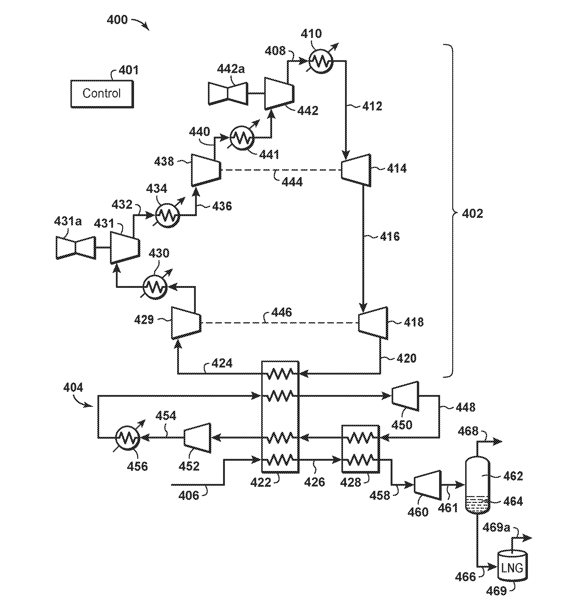
[0051] FIG. 4 illustrates a liquefaction system 400 according to disclosed aspects. Liquefaction system includes a primary cooling loop 402 and a sub-cooling loop 404. A compressed refrigerant stream 408 is cooled in a first heat exchanger having one or more coolers 410, which may use one or more cooling mediums to produce a compressed, cooled refrigerant stream 412. The compressed, cooled refrigerant stream 412 is expanded in a first expander 414 to an intermediate pressure, and is thereby further cooled to produce a first expanded, cooled refrigerant stream 416. The first expander 414 is coupled, using a first mechanical coupling 444, to a first coupled compressor 438 to together form a high-pressure turboexpander/compressor (TEC). The first expanded, cooled refrigerant stream is additionally expanded in a second expander 418 to further cool the first expanded, cooled refrigerant stream 416 and thereby produce a second expanded, cooled refrigerant stream 420. The second expander 414 is coupled, using a second mechanical coupling 446, to a second coupled compressor 429 to together form a low-pressure TEC. The second expanded, cooled refrigerant stream 420 is directed to a main heat exchange area 422 comprising one or more heat exchangers, where the second expanded, cooled refrigerant stream exchanges heat with the feed gas stream 406 to produce a warm refrigerant stream 424 and a liquefied gas stream 426. The liquefied gas stream 426 is further cooled in a sub-cooling heat exchanger 428 using the sub-cooling loop 404, which will be further described. The warm refrigerant stream 424 is compressed by second coupled compressor 429, cooled via indirect heat exchange with a cooling medium in a second cooler 430, and is further compressed by a first driven compressor 431 to produce a first compressed refrigerant stream 432. The first driven compressor may be driven by a gas turbine 431a, or alternatively may be driven by a reciprocating engine, a steam turbine, or a motor. The first compressed refrigerant stream 432 has a discharge pressure what is within 300 psia, or within 250 psia, or within 200 psia, or within 150 psia, or within 100 psia, of the intermediate pressure of the first expanded, cooled refrigerant stream 416. The first compressed refrigerant stream is cooled in a third cooler 434 via indirect heat exchange with a cooling medium to form a first compressed, cooled refrigerant stream 436, which is then compressed in first coupled compressor 438 to form a second compressed refrigerant stream 440. The second compressed refrigerant stream may be cooled in a fourth cooler 441 via indirect heat exchange with a cooling medium and then further compressed in a second driven compressor 442 to produce the compressed refrigerant stream 408. The second driven compressor 442 may be driven by a gas turbine 442a, or alternatively may be driven by a reciprocating engine, a steam turbine, or a motor. The second driven compressor 442 may share a common driver with first driven compressor 431. The first and second driven compressors 431, 442 may even be disposed within a single compressor casing.
[0052] In sub-cooling loop 404, an expanded sub-cooling refrigerant stream 448 (preferably comprising nitrogen) is discharged from a sub-cooling expander 450 and drawn through the sub-cooling heat exchanger 428 and the heat exchangers in the main heat exchange area 422. Expanded sub-cooling refrigerant stream 448 is then sent to a sub-cooling compression unit 452 where it is re-compressed to a higher pressure and warmed, thereby forming a re-compressed sub-cooling refrigerant stream 454. After exiting compression unit 442, the re-compressed sub-cooling refrigerant stream 454 is cooled in a fifth heat exchanger comprising a cooler 456, which can be of the same type as coolers 410 and/or 434, although any type of cooler may be used. After cooling, the re-compressed sub-cooling refrigerant stream 454 is passed through the heat exchangers in the main heat exchange area 422 where it is further cooled by indirect heat exchange with second expanded, cooled refrigerant stream 420 and expanded sub-cooling refrigerant stream 448. After exiting the heat exchange area 422, the re-compressed and cooled sub-cooling refrigerant stream is expanded through sub-cooling expander 450 to provide the expanded, sub-cooled refrigerant stream 448, which is then passed through sub-cooling heat exchanger 428 to sub-cool the feed gas stream, and thereby produce a sub-cooled feed gas stream 458. Sub-cooled feed gas stream 458 is then expanded to a lower pressure in an expander 460 to form an expanded, sub-cooled gas stream 461 with a liquid fraction and a remaining vapor fraction. In an aspect, the expanded, sub-cooled gas stream 461 may have a pressure greater than or equal to 50 psia and less than or equal to 450 psia. Expander 460 may be any pressure reducing device, including, but not limited to a valve, control valve, Joule Thompson valve, Venturi device, liquid expander, hydraulic turbine, and the like. The expanded sub-cooled gas stream 461, which is now at a lower pressure and partially liquefied, is passed to a surge tank 462 where the liquefied fraction 464 is withdrawn from the process as an LNG stream 466. The LNG stream 466 has a temperature corresponding to the bubble point pressure. The remaining vapor fraction (flash vapor) stream 468 may be used as fuel to power the compressor units.
[0053] The discharge pressure of one or more of the compressors and/or expanders disclosed herein may be controlled by a control system 401. Such a control system may include control logic to optimize cycle efficiency by maximizing certain parameters within a measured thrust bearing limit, such as temperature. The control logic may also control one or more of, for example, the driven compressor speed, driven compressor recycle valves, first coupled compressor recycle valves, second coupled compressor recycle valves, first expander bypass valves, second expander bypass valves, first expander throttling valves, second expander throttling valves, first expander inlet guide vanes, second expander inlet guide vanes, or any combination of the foregoing based on the suction pressure of the driven compressor, discharge pressure of the driven compressor, discharge pressure of the first couple compressor, discharge pressure of the second coupled compressor, discharge pressure of the first expander, discharge pressure of the second expander, and/or suction pressure of the second expander, or any combination thereof. The control system may adjust one or more of (a) a discharge pressure of one or more of the compressors, and (b) an inlet pressure of one or more of the expanders, to thereby maintain a fixed differential pressure between the discharge pressure and the inlet pressure. The fixed differential pressure may be obtained through control algorithms using one or more of compressor speed of one or more of the compressors, inlet guide vanes of one or more of the expanders, recycle valves of one or more of the compressors, and bypass valves of one or more of the expanders. Furthermore, cycle efficiency may be optimized by maximizing certain parameters within a measured thrust bearing limit, such as temperature. For the sake of clarity in the Figures, necessary connections from control system 401 to the various valves, compressors and expanders, are not shown.
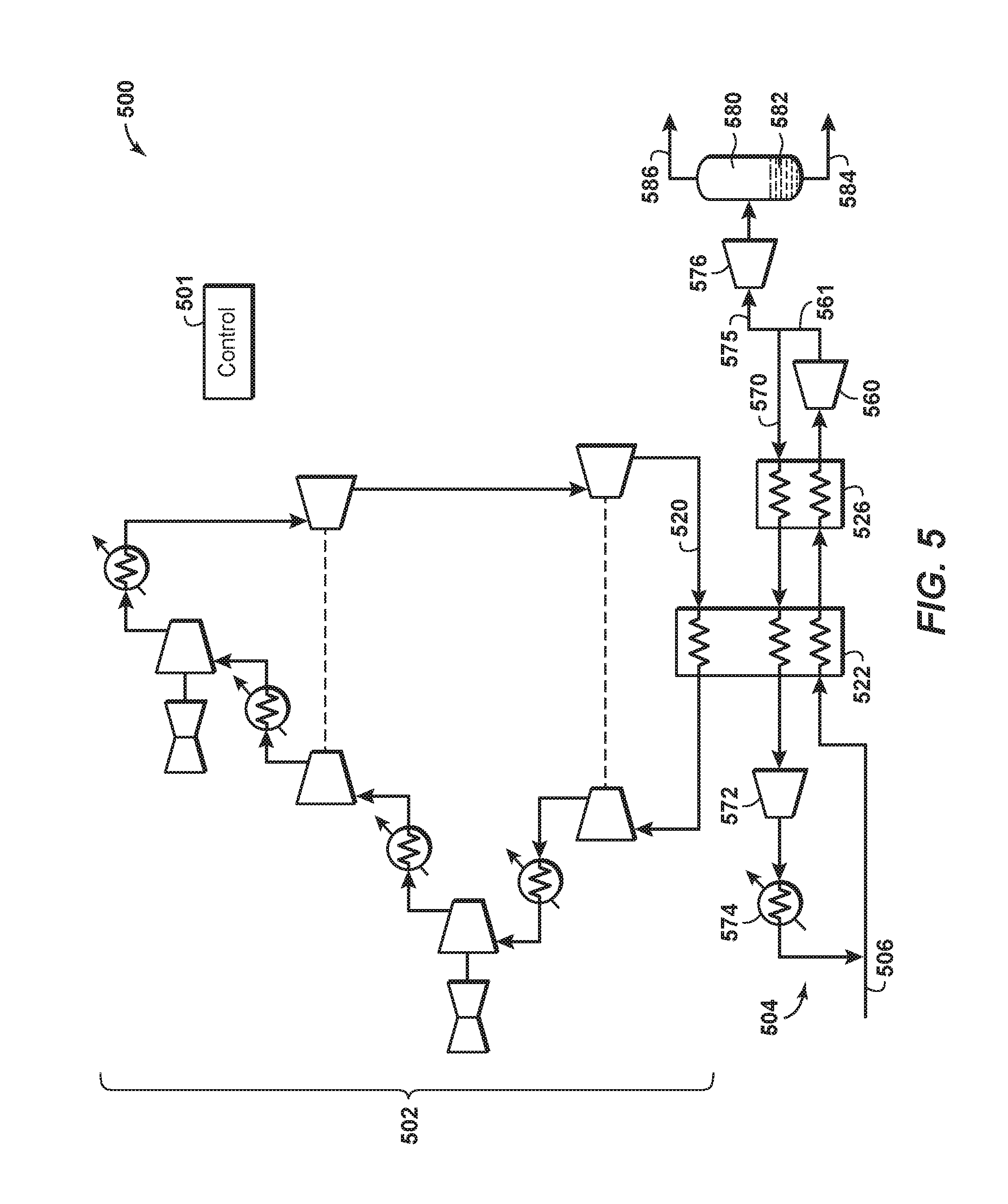
[0054] FIG. 5 is a schematic diagram that illustrates a liquefaction system 500 according to another aspect of the disclosure. Liquefaction system 500 is similar to liquefaction system 400 (FIG. 4), and for the sake of brevity similarly depicted or numbered components may not be further described. Liquefaction system 500 includes a primary cooling loop 502, which is substantially identical to primary cooling loop 402, and a sub-cooling loop 504. The sub-cooling loop 504 is an open refrigeration loop where a portion 570 of the expanded, sub-cooled feed gas stream 561 is recycled and used as the sub-cooling refrigerant stream. Specifically, the portion 570 of the expanded, sub-cooled gas stream 561 is directed through a sub-cooling heat exchanger 526 and one or more heat exchangers in a main heat exchange area 522 before being compressed in a compressor 572, cooled in a cooler 574 via indirect heat exchange with a cooling medium, and re-inserted into the feed gas stream 506. The feed gas stream 506 passes through the heat exchangers in the heat exchange area 522, where it is cooled by indirect heat exchange with the portion of the expanded, sub-cooled gas stream 561 and the second expanded, cooled refrigerant stream 520 of the primary cooling loop 502. After being expanded in an expander 560, the portion 575 of the sub-cooled feed gas stream 561 not used as the sub-cooling refrigerant stream is further expanded and cooled in an expander 576, which may be any pressure reducing device, including, but not limited to a valve, control valve, Joule Thompson valve, Venturi device, liquid expander, hydraulic turbine, and the like. The sub-cooled gas stream, which is now at a lower pressure and partially liquefied, is passed to a surge tank 580 where the liquefied fraction 582 is withdrawn from the process as an LNG stream 584. The LNG stream 584 has a temperature corresponding to the bubble point pressure. The remaining vapor fraction (flash vapor) stream 586 may be used as fuel to power the compressor units. Liquefaction system 500 also includes a control system 501 having similar functionality as control system 401 (FIG. 4).
[0055] The sub-cooling refrigerant stream in FIG. 5 may be one stream, as shown, or may comprise multiple streams at different pressures: for example, a portion of the expanded, sub-cooling gas stream--not to exceed 50% thereof--may be diverted and pass through one or more pressure reduction valves to reduce its pressure to a range of about 30 to 300 psia, to thereby produce one or more reduced pressure gas streams. The reduced pressure gas streams may then be passed through the first heat exchanger zone as the sub-cooling refrigerant. Having multiple streams improves the efficiency of the sub-cooling process. Alternatively, this sub-cooling loop may be configured to be a closed refrigeration loop.
[0056] Aspects of the disclosure illustrated in FIG. 5 demonstrate that the primary refrigerant stream may comprise part of the feed gas stream, which in a preferred aspect may be primarily or nearly all methane. Indeed, it may be advantageous for the refrigerant in the primary cooling loop of FIG. 4 to be comprised of at least 85% methane, or at least 90% methane, or at least 95% methane, or greater than 95% methane. This is because methane may be readily available in various parts of the disclosed processes, and the use of methane may eliminate the need to transport refrigerants to remote LNG processing locations. As a non-limiting example, the refrigerant in the primary cooling loop 402 in FIG. 4 may be taken directly from feed gas stream 406 if the feed gas is high enough in methane to meet the compositions as described above. Alternatively, part or all of a boil-off gas stream 469a from an LNG storage tank 469 may be used to supply refrigerant for the primary cooling loop 402. Furthermore, if the feed gas stream is sufficiently low in nitrogen, part or all of the end flash gas stream 468 (which would then be low in nitrogen) may be used to supply refrigerant for the primary cooling loop 402. Lastly, any combination of feed gas stream 406, boil-off gas stream 469a, and end flash gas stream 468 may be used to provide or even occasionally replenish the refrigerant in the primary cooling loop 402.
[0057] Aspects of the disclosure have shown how two TECs--i.e., a high pressure TEC and a low-pressure TEC--can be disposed in series in a high-pressure refrigerant stream for liquefying natural gas. It is within the scope of the disclosed aspects to employ three or more TECs in series in the high-pressure refrigerant stream for liquefying natural gas.
[0058] The coolers disclosed in FIGS. 4 and 5 may use any type of cooling media, including air or water. For purposes of clarity, the various disclosed cooling media may be denoted as a `first cooling medium,` `second cooling medium,` etc., it being understood that one or more of the cooling media used herein have similar or identical composition, regardless of how they have been denoted.
[0059] FIG. 6 is a flowchart of a method 600 for liquefying a feed gas stream comprising natural gas. At block 602 the feed gas stream is provided at a pressure less than 1,200 psia. At block 604 a compressed refrigerant stream is provided with a pressure greater than or equal to 1,500 psia. At block 606 the compressed refrigerant stream is cooled by indirect heat exchange with a cooling medium, thereby producing a compressed, cooled refrigerant stream. At block 608 the compressed, cooled refrigerant stream is expanded in a first expander to an intermediate pressure to further cool the compressed, cooled refrigerant stream, thereby producing a first expanded, cooled refrigerant stream. The first expander is mechanically coupled to a first coupled compressor to together form a first turboexpander-compressor. At block 610 the first expanded, cooled refrigerant stream is expanded in a second expander to further cool the first expanded, cooled refrigerant stream, thereby producing a second expanded, cooled refrigerant stream. The second expander is mechanically coupled to a second coupled compressor to together form a second turboexpander-compressor. At block 612 the second expanded, cooled refrigerant stream is passed through one or more heat exchangers, thereby forming a warm refrigerant stream. At block 614 the feed gas stream is passed through the one or more heat exchangers to cool at least part of the feed gas stream by indirect heat exchange with the second expanded, cooled refrigerant stream, thereby forming a cool feed gas stream. At block 616, using the second coupled compressor and a first driven compressor, the warm refrigerant stream is compressed to a discharge pressure within 300 psia of the intermediate pressure, thereby forming a first compressed refrigerant stream. At block 618 the first compressed refrigerant stream is compressed using the first coupled compressor, thereby forming a second compressed refrigerant stream. At block 620 the second compressed refrigerant stream is compressed to provide the compressed refrigerant stream.
[0060] FIG. 7 is a flowchart of a method 700 for liquefying a feed gas stream comprising natural gas. At block 702 the feed gas stream is provided at a pressure less than 1,200 psia. At block 704 a compressed refrigerant stream is provided with a pressure greater than or equal to 1,500 psia. At block 706 the compressed refrigerant stream is cooled by indirect heat exchange with a first cooling medium, thereby producing a compressed, cooled refrigerant stream. At block 708 the compressed, cooled refrigerant stream is expanded in a first expander to an intermediate pressure to further cool the compressed, cooled refrigerant stream, thereby producing a first expanded, cooled refrigerant stream. The first expander is mechanically coupled to a first coupled compressor to together form a first turboexpander-compressor. At block 710 the first expanded, cooled refrigerant stream is expanded in a second expander to further cool the first expanded, cooled refrigerant stream, thereby producing a second expanded, cooled refrigerant stream. The second expander is mechanically coupled to a second coupled compressor to together form a second turboexpander-compressor. At block 712 the second expanded, cooled refrigerant stream is passed through one or more heat exchangers, thereby forming a warm refrigerant stream. At block 714 the feed gas stream is passed through the one or more heat exchangers to cool at least part of the feed gas stream by indirect heat exchange with the second expanded, cooled refrigerant stream, thereby forming a cool feed gas stream. At block 716, using a sub-cooling loop, the cool feed gas stream is further cooled to form a sub-cooled feed gas stream having a liquid portion. At block 718, using the second coupled compressor and a first driven compressor, the warm refrigerant stream is compressed to a discharge pressure within 300 psia of the intermediate pressure, thereby forming a first compressed refrigerant stream. At block 720 the warm refrigerant stream is cooled by indirect heat exchange with a second cooling medium after being compressed in the second coupled compressor and prior to being compressed in the first driven compressor. At block 722 the first compressed refrigerant stream is cooled via heat exchange with a third cooling medium. At block 724 the first compressed refrigerant stream is compressed using the first coupled compressor, thereby forming a second compressed refrigerant stream. At block 726 the second compressed refrigerant stream is cooled via heat exchange with a fourth cooling medium. At block 728 the second compressed refrigerant stream is compressed to provide the compressed refrigerant stream.
[0061] The steps depicted in FIGS. 6 and 7 are provided for illustrative purposes only and a particular step may not be required to perform the disclosed methodology. Moreover, FIGS. 6-7 may not illustrate all the steps that may be performed. The claims, and only the claims, define the disclosed system and methodology.
[0062] The aspects described herein have several advantages over known technologies. For example, the described technology may greatly reduce the size and cost of systems that treat sour natural gas.
[0063] Aspects of the disclosure may include any combinations of the methods and systems shown in the following numbered paragraphs. This is not to be considered a complete listing of all possible aspects, as any number of variations can be envisioned from the description above.
1. A method for liquefying a feed gas stream comprising natural gas, the method comprising:
[0064] providing the feed gas stream at a pressure less than 1,200 psia;
[0065] providing a compressed refrigerant stream with a pressure greater than or equal to 1,500 psia;
[0066] cooling the compressed refrigerant stream by indirect heat exchange with a cooling medium, thereby producing a compressed, cooled refrigerant stream;
[0067] expanding the compressed, cooled refrigerant stream in a first expander to an intermediate pressure to further cool the compressed, cooled refrigerant stream, thereby producing a first expanded, cooled refrigerant stream, wherein the first expander is mechanically coupled to a first coupled compressor to together form a first turboexpander-compressor;
[0068] expanding the first expanded, cooled refrigerant stream in a second expander to further cool the first expanded, cooled refrigerant stream, thereby producing a second expanded, cooled refrigerant stream, wherein the second expander is mechanically coupled to a second coupled compressor to together form a second turboexpander-compressor;
[0069] passing the second expanded, cooled refrigerant stream to one or more heat exchangers, thereby forming a warm refrigerant stream;
[0070] passing the feed gas stream through the one or more heat exchangers to cool at least part of the feed gas stream by indirect heat exchange with the second expanded, cooled refrigerant stream, thereby forming a cool feed gas stream;
[0071] using the second coupled compressor and a first driven compressor, compressing the warm refrigerant stream to a discharge pressure within 300 psia of the intermediate pressure, thereby forming a first compressed refrigerant stream;
[0072] compressing the first compressed refrigerant stream using the first coupled compressor, thereby forming a second compressed refrigerant stream; and
[0073] compressing the second compressed refrigerant stream to provide the compressed refrigerant stream.
2. The method of paragraph 1, further comprising driving the first driven compressor using at least one of a reciprocating engine, a steam turbine, a gas turbine, and a motor. 3. The method of paragraph 1 or paragraph 2, wherein cooling the compressed refrigerant stream comprises cooling the compressed refrigerant stream via indirect heat exchange with a cooling medium. 4. The method of any one of paragraphs 1-3, wherein cooling the compressed refrigerant stream comprises cooling the compressed refrigerant stream by indirect heat exchange with a cooling medium having a temperature lower than ambient conditions. 5. The method of any one of paragraphs 1-4, further comprising:
[0074] cooling the warm refrigerant stream by indirect heat exchange with a cooling medium after being compressed in the second coupled compressor and prior to being compressed in the first driven compressor.
6. The method of any one of paragraphs 1-5, further comprising:
[0075] cooling the first compressed refrigerant stream prior to being compressed in the first coupled compressor.
7. The method of any one of paragraphs 1-6, further comprising:
[0076] cooling the second compressed refrigerant stream via indirect heat exchange with a cooling medium prior to being compressed to provide the compressed refrigerant stream.
8. The method of any one of paragraphs 1-7, wherein the compressed refrigerant stream has a pressure of approximately 3,000 psia. 9. The method of any one of paragraphs 1-8, wherein the intermediate pressure is less than 1,500 psia and greater than 1,000 psia. 10. The method of any one of paragraphs 1-9, wherein compressing the second compressed refrigerant stream is accomplished using a second driven compressor. 11. The method of paragraph 10, further comprising:
[0077] driving the second driven compressor using at least one of a reciprocating engine, a steam turbine, a gas turbine, and a motor.
12. The method of paragraph 10 or paragraph 11, wherein the first driven compressor and the second driven compressor share a common driver. 13. The method of any one of paragraphs 10-12, wherein the first driven compressor and the second driven compressor are within a single compressor casing. 14. The method of any one of paragraphs 1-13, further comprising:
[0078] using a sub-cooling loop, further cooling the cool feed gas stream to form a sub-cooled feed gas stream.
15. The method of paragraph 14, further comprising:
[0079] expanding the sub-cooled feed gas stream to a pressure greater than or equal to 50 psia and less than or equal to 450 psia, to produce an expanded, sub-cooled feed gas stream.
16. The method of paragraph 14 or paragraph 15, wherein the sub-cooled feed gas stream is expanded within a hydraulic turbine. 17. The method of any one of paragraphs 14-16, wherein the sub-cooling loop is a closed loop gas phase refrigeration cycle where nitrogen gas is the refrigerant. 18. The method of paragraph 14, wherein the sub-cooling loop comprises:
[0080] withdrawing a portion not to exceed 50% of the expanded, sub-cooled gas stream and reducing its pressure in a pressure reduction valve to a range of about 30 to 300 psia to produce one or more reduced pressure gas streams; and
[0081] passing the one or more reduced pressure gas streams through the one or more heat exchangers as the sub-cooling refrigerant stream.
19. The method of paragraph 18, wherein the one or more reduced pressure gas streams are at different pressures from each other. 20. The method of paragraph 18 or paragraph 19, wherein the sub-cooling refrigerant stream exiting the one or more heat exchangers is compressed to a pressure approximate to that of the feed gas stream and is cooled by indirect heat exchange with a cooling medium before mixing the sub-cooling refrigerant stream with the feed gas stream. 21. The method of paragraph 15, wherein at least a portion of the expanded, sub-cooled gas stream is further expanded and then directed to a separation tank from which liquid natural gas is withdrawn and remaining gaseous vapors are withdrawn as a flash gas stream. 22. The method of paragraph 21, wherein the compressed refrigerant stream comprises boil off gas of the liquid natural gas. 23. The method of any one of paragraphs 1-22, further comprising:
[0082] adjusting one or more of [0083] a discharge pressure of one or more of the compressors, and [0084] an inlet pressure of one or more of the expanders, to thereby maintain a fixed differential pressure between the discharge pressure and the inlet pressure. 24. The method of paragraph 23, wherein the fixed differential pressure is obtained through control algorithms using one or more of compressor speed of one or more of the compressors, inlet guide vanes of one ore more of the expanders, recycle valves of one or more of the compressors, and bypass valves of one or more of the expanders. 25. The method of paragraph 23 or paragraph 24, further comprising:
[0085] using expander thrust bearing temperature as a limit to protect thrust bearing integrity while maximizing cycle efficiency.
26. A natural gas liquefaction system comprising:
[0086] a first heat exchanger configured to cool a compressed refrigerant stream by indirect heat exchange with a cooling medium, thereby producing a compressed, cooled refrigerant stream, wherein the compressed refrigerant stream is provided to the first heat exchanger at a pressure of at least 1,500 psia;
[0087] a first expander configured to expand the compressed, cooled refrigerant stream to an intermediate pressure, to further cool the compressed, cooled refrigerant stream, thereby producing a first expanded, cooled refrigerant stream;
[0088] a first coupled compressor mechanically coupled to the first expander to together form a first turboexpander-compressor;
[0089] a second expander configured to expand the first expanded, cooled refrigerant stream to further cool the first expanded, cooled refrigerant stream, thereby producing a second expanded, cooled refrigerant stream;
[0090] a second coupled compressor mechanically coupled to the second expander to together form a second turboexpander-compressor;
[0091] one or more heat exchangers arranged to permit the second expanded, cooled refrigerant stream and a feed gas stream to pass therethrough and exchange heat therein through indirect heat exchange, thereby forming a warm refrigerant stream and a cool feed gas stream, wherein the feed gas stream comprises natural gas and is supplied to the one or more heat exchangers at a pressure of less than 1,200 psia;
[0092] a first driven compressor configured to, along with the second coupled compressor, compress the warm refrigerant stream to a discharge pressure within 300 psia of the intermediate pressure, thereby forming a first compressed refrigerant stream;
[0093] wherein the first compressed refrigerant stream is further compressed using the first coupled compressor, thereby forming a second compressed refrigerant stream; and
[0094] wherein the second compressed refrigerant stream is compressed to provide the compressed refrigerant stream.
27. The system of paragraph 26, further comprising a driving element configured to drive the first driven compressor, wherein the driving element comprises at least one of a reciprocating engine, a steam turbine, a gas turbine, and a motor. 28. The system of paragraph 26 or paragraph 27, further comprising:
[0095] a first cooler configured to cool the compressed refrigerant stream via indirect heat exchange with a cooling medium.
29. The system of paragraph 28, wherein the cooling medium has a temperature lower than ambient conditions. 30. The system of any one of paragraphs 26-29, further comprising:
[0096] a second cooler configured to cool the warm refrigerant stream by indirect heat exchange with a cooling medium after being compressed in the second coupled compressor and prior to being compressed in the first driven compressor;
[0097] a third cooler configured to cool the first compressed refrigerant stream prior to being compressed in the first coupled compressor; and
[0098] a fourth cooler configured to cool the second compressed refrigerant stream via indirect heat exchange with a cooling medium prior to being compressed, to thereby provide the compressed refrigerant stream.
31. The system of any one of paragraphs 26-30, wherein the compressed refrigerant stream has a pressure of approximately 3,000 psia. 32. The system of any one of paragraphs 26-31, wherein the intermediate pressure is less than 1,500 psia and greater than 1,000 psia. 33. The system of any one of paragraphs 26-32, further comprising:
[0099] a second driven compressor configured to compress the second compressed refrigerant stream.
34. The system of paragraph 33, further comprising:
[0100] a driving element configured to drive the second driven compressor, wherein the driving element comprises at least one of a reciprocating engine, a steam turbine, a gas turbine, and a motor.
35. The system of paragraph 33 or paragraph 34, wherein the first driven compressor and the second driven compressor share a common driver. 36. The system of any one of paragraphs 32-34, wherein the first driven compressor and the second driven compressor are within a single compressor casing. 37. The system of any one of paragraphs 26-33, further comprising a sub-cooling loop configured to further cool the cool feed gas stream to form a sub-cooled feed gas stream. 38. The system of paragraph 37, further comprising:
[0101] a hydraulic turbine configured to expand the sub-cooled feed gas stream to a pressure greater than or equal to 50 psia and less than or equal to 450 psia, to thereby produce an expanded, sub-cooled feed gas stream.
39. The system of paragraph 37 or paragraph 38, wherein the sub-cooling loop is a closed loop gas phase refrigeration cycle where nitrogen gas is the refrigerant. 40. A method for liquefying a feed gas stream comprising natural gas, the method comprising:
[0102] providing the feed gas stream at a pressure less than 1,200 psia;
[0103] providing a compressed refrigerant stream with a pressure greater than or equal to 1,500 psia;
[0104] cooling the compressed refrigerant stream by indirect heat exchange with a first cooling medium, thereby producing a compressed, cooled refrigerant stream;
[0105] expanding the compressed, cooled refrigerant stream in a first expander to an intermediate pressure to further cool the compressed, cooled refrigerant stream, thereby producing a first expanded, cooled refrigerant stream, wherein the first expander is mechanically coupled to a first coupled compressor to together form a first turboexpander-compressor;
[0106] expanding the first expanded, cooled refrigerant stream in a second expander to further cool the first expanded, cooled refrigerant stream, thereby producing a second expanded, cooled refrigerant stream, wherein the second expander is mechanically coupled to a second coupled compressor to together form a second turboexpander-compressor;
[0107] passing the second expanded, cooled refrigerant stream to one or more heat exchangers, thereby forming a warm refrigerant stream;
[0108] passing the feed gas stream through the one or more heat exchangers to cool at least part of the feed gas stream by indirect heat exchange with the second expanded, cooled refrigerant stream, thereby forming a cool feed gas stream;
[0109] using a sub-cooling loop, further cooling the cool feed gas stream to form a sub-cooled feed gas stream having a liquid portion;
[0110] using the second coupled compressor and a first driven compressor, compressing the warm refrigerant stream to a discharge pressure within 300 psia of the intermediate pressure, thereby forming a first compressed refrigerant stream;
[0111] cooling the warm refrigerant stream by indirect heat exchange with a second cooling medium after being compressed in the second coupled compressor and prior to being compressed in the first driven compressor;
[0112] cooling the first compressed refrigerant stream via heat exchange with a third cooling medium;
[0113] compressing the first compressed refrigerant stream using the first coupled compressor, thereby forming a second compressed refrigerant stream;
[0114] cooling the second compressed refrigerant stream via heat exchange with a fourth cooling medium; and
[0115] compressing the second compressed refrigerant stream to provide the compressed refrigerant stream.
41. The method of paragraph 40, wherein at least one of the first cooling medium, the second cooling medium, the third cooling medium, and the fourth cooling medium comprises air or water.
[0116] It should be understood that the numerous changes, modifications, and alternatives to the preceding disclosure can be made without departing from the scope of the disclosure. The preceding description, therefore, is not meant to limit the scope of the disclosure. Rather, the scope of the disclosure is to be determined only by the appended claims and their equivalents. It is also contemplated that structures and features in the present examples can be altered, rearranged, substituted, deleted, duplicated, combined, or added to each other.
* * * * *
D00000
D00001
D00002
D00003
D00004
D00005
D00006
XML
uspto.report is an independent third-party trademark research tool that is not affiliated, endorsed, or sponsored by the United States Patent and Trademark Office (USPTO) or any other governmental organization. The information provided by uspto.report is based on publicly available data at the time of writing and is intended for informational purposes only.
While we strive to provide accurate and up-to-date information, we do not guarantee the accuracy, completeness, reliability, or suitability of the information displayed on this site. The use of this site is at your own risk. Any reliance you place on such information is therefore strictly at your own risk.
All official trademark data, including owner information, should be verified by visiting the official USPTO website at www.uspto.gov. This site is not intended to replace professional legal advice and should not be used as a substitute for consulting with a legal professional who is knowledgeable about trademark law.