Transport Refrigeration Unit With Battery Boost
CHOPKO; Robert A. ; et al.
U.S. patent application number 16/091812 was filed with the patent office on 2019-04-25 for transport refrigeration unit with battery boost. This patent application is currently assigned to Carrier Corporation. The applicant listed for this patent is CARRIER CORPORATION. Invention is credited to Yu H. CHEN, Robert A. CHOPKO, Greg DELDICQUE.
| Application Number | 20190120530 16/091812 |
| Document ID | / |
| Family ID | 58549280 |
| Filed Date | 2019-04-25 |

| United States Patent Application | 20190120530 |
| Kind Code | A1 |
| CHOPKO; Robert A. ; et al. | April 25, 2019 |
TRANSPORT REFRIGERATION UNIT WITH BATTERY BOOST
Abstract
A transport refrigeration unit (26) includes a compressor (58) constructed and arranged to compress a refrigerant and an electric compressor motor configured to drive the compressor. A generator (54) of the unit is configured to provide electric power to the compressor motor during standard set point conditions, and an energy storage device of the unit is configured to supplement the electric power to the compressor motor during temperature pulldown conditions.
| Inventors: | CHOPKO; Robert A.; (Baldwinsville, NY) ; CHEN; Yu H.; (Manlius, NY) ; DELDICQUE; Greg; (Fayetteville, NY) | ||||||||||
| Applicant: |
|
||||||||||
|---|---|---|---|---|---|---|---|---|---|---|---|
| Assignee: | Carrier Corporation Palm Beach Gardens CT |
||||||||||
| Family ID: | 58549280 | ||||||||||
| Appl. No.: | 16/091812 | ||||||||||
| Filed: | April 4, 2017 | ||||||||||
| PCT Filed: | April 4, 2017 | ||||||||||
| PCT NO: | PCT/US2017/025911 | ||||||||||
| 371 Date: | October 5, 2018 |
Related U.S. Patent Documents
| Application Number | Filing Date | Patent Number | ||
|---|---|---|---|---|
| 62318602 | Apr 5, 2016 | |||
| Current U.S. Class: | 1/1 |
| Current CPC Class: | F25B 27/00 20130101; F25D 11/003 20130101; F25B 31/02 20130101; F25B 13/00 20130101 |
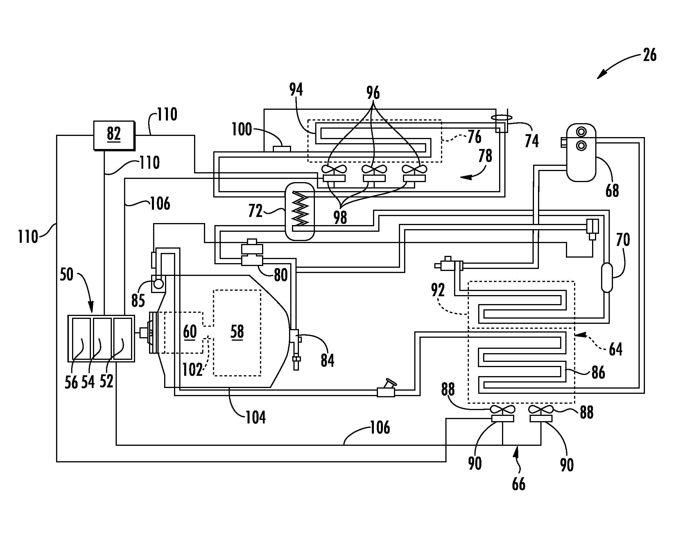
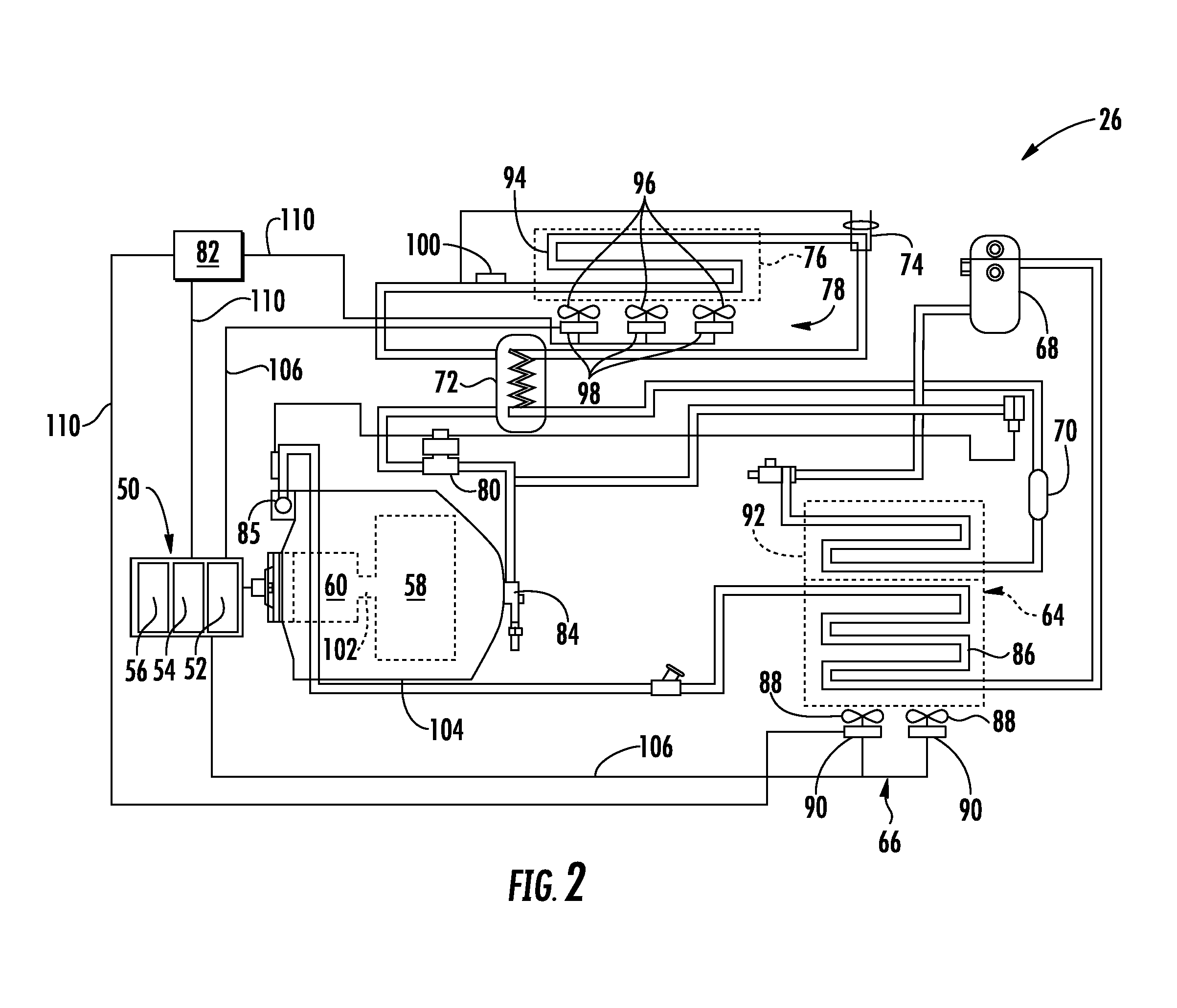
| International Class: | F25B 27/00 20060101 F25B027/00; F25B 13/00 20060101 F25B013/00; F25D 11/00 20060101 F25D011/00; F25B 31/02 20060101 F25B031/02 |
Claims
1. A transport refrigeration unit comprising: a compressor constructed and arranged to compress a refrigerant; an electric compressor motor configured to drive the compressor; a generator configured to provide electric power to the compressor motor during standard set point conditions; and an energy storage device configured to supplement the electric power to the compressor motor during temperature pulldown conditions at least one heat exchanger operatively coupled to the compressor; at least one fan configured to provide air flow over the at least one heat exchanger; and at least one electric fan motor configured to drive the at least one fan, and wherein the generator is configured to provide electric power to the at least one fan motor during standard set point conditions.
2-3. (canceled)
4. The transport refrigeration unit set forth in claim 1, wherein the energy storage device is configured to supplement the electric power to the at least one fan motor during temperature pulldown conditions.
5. The transport refrigeration unit set forth in claim 4, wherein the at least one heat exchanger includes an evaporator heat exchanger, the at least one fan includes an evaporator fan, and the at least one electric fan motor includes an evaporator fan motor.
6. The transport refrigeration unit set forth in claim 5, wherein the at least one heat exchanger includes a condenser heat exchanger, the at least one fan includes a condenser fan, and the at least one electric fan motor includes a condenser fan motor.
7. The transport refrigeration unit set forth in claim 1, wherein the refrigerant is a natural refrigerant.
8. The transport refrigeration unit set forth in claim 6, wherein the refrigerant is a natural refrigerant.
9. The transport refrigeration unit set forth in claim 1, wherein the energy storage device is a battery.
10. The transport refrigeration unit set forth in claim 9, wherein the battery has a voltage potential with a range of about 48V to 250V.
11. A method of operating a transport refrigeration unit comprising: utilizing one of an electric generator and an energy storage device to provide electric power generally during steady state conditions; and providing supplemental power from the other of the electric generator and the energy storage device during a temperature pull down state.
12. The method set forth in claim 11, wherein the energy storage device is a battery.
13. The method set forth in claim 11, wherein the supplemental power is provided to a compressor motor.
14. The method set forth in claim 11, wherein the compressor motor is an alternating current motor and the supplemental power is delivered through an inverter.
15. The method set forth in claim 14, wherein the electric generator has a maximum power output that is less than a system power load during the temperature pull down state.
16. The method set forth in claim 11 further comprising: charging the energy storage device by the electric generator during part load operating conditions.
17. The method set forth in claim 11 further comprising: driving the electric generator by a combustion engine.
18. The method set forth in claim 14, wherein an evaporator fan motor and a condenser fan motor of the transport refrigeration unit are direct current motors.
19. The method set forth in claim 11, wherein the electric generator provides the power to a compressor motor, an evaporator fan motor and a condenser fan motor during steady state conditions.
20. The method set forth in claim 11, wherein the energy storage device provides the power to a compressor motor, an evaporator fan motor and a condenser fan motor during steady state conditions.
21. A transport refrigeration unit comprising: a compressor constructed and arranged to compress a refrigerant; an electric compressor motor configured to drive the compressor; a generator configured to provide electric power to the compressor motor during standard set point conditions; and an energy storage device configured to supplement the electric power to the compressor motor during temperature pulldown conditions; at least one heat exchanger operatively coupled to the compressor; at least one fan configured to provide air flow over the at least one heat exchanger; and at least one electric fan motor configured to drive the at least one fan, and wherein the energy storage device is configured to provide electric power to the at least one fan motor during standard set point conditions.
Description
BACKGROUND
[0001] The present disclosure relates to transport refrigeration units and, more particularly, to all-electric transport refrigeration units.
[0002] Traditional refrigerated cargo trucks or refrigerated tractor trailers, such as those utilized to transport cargo via sea, rail, or road, is a truck, trailer or cargo container, generally defining a cargo compartment, and modified to include a refrigeration system located at one end of the truck, trailer, or cargo container. Refrigeration systems typically include a compressor, a condenser, an expansion valve, and an evaporator serially connected by refrigerant lines in a closed refrigerant circuit in accord with known refrigerant vapor compression cycles. A power unit, such as a combustion engine, drives the compressor of the refrigeration unit, and may be diesel powered, natural gas powered, or other type of engine. In many tractor trailer transport refrigeration systems, the compressor is driven by the engine shaft either through a belt drive or by a mechanical shaft-to-shaft link. In other systems, the engine of the refrigeration unit drives a generator that generates electrical power, which in-turn drives the compressor.
[0003] With current environmental trends, improvements in transport refrigeration units are desirable particularly toward aspects of environmental impact. With environmentally friendly refrigeration units, improvements in reliability, cost, and weight reduction are also desirable.
SUMMARY
[0004] A transport refrigeration unit according to one, non-limiting, embodiment of the present disclosure includes a compressor constructed and arranged to compress a refrigerant; an electric compressor motor configured to drive the compressor; a generator configured to provide electric power to the compressor motor during standard set point conditions; and an energy storage device configured to supplement the electric power to the compressor motor during temperature pulldown conditions.
[0005] Additionally to the foregoing embodiment, the transport refrigeration unit includes at least one heat exchanger operatively coupled to the compressor; at least one fan configured to provide air flow over the at least one heat exchanger; and at least one electric fan motor configured to drive the at least one fan, and wherein the generator is configured to provide electric power to the at least one fan motor during standard set point conditions.
[0006] In the alternative or additionally thereto, in the foregoing embodiment, the transport refrigeration unit includes at least one heat exchanger operatively coupled to the compressor; at least one fan configured to provide air flow over the at least one heat exchanger; and at least one electric fan motor configured to drive the at least one fan, and wherein the energy storage device is configured to provide electric power to the at least one fan motor during standard set point conditions.
[0007] In the alternative or additionally thereto, in the foregoing embodiment, the energy storage device is configured to supplement the electric power to the at least one fan motor during temperature pulldown conditions.
[0008] In the alternative or additionally thereto, in the foregoing embodiment, the at least one heat exchanger includes an evaporator heat exchanger, the at least one fan includes an evaporator fan, and the at least one electric fan motor includes an evaporator fan motor.
[0009] In the alternative or additionally thereto, in the foregoing embodiment, the at least one heat exchanger includes a condenser heat exchanger, the at least one fan includes a condenser fan, and the at least one electric fan motor includes a condenser fan motor.
[0010] In the alternative or additionally thereto, in the foregoing embodiment, the refrigerant is a natural refrigerant.
[0011] In the alternative or additionally thereto, in the foregoing embodiment, the refrigerant is a natural refrigerant.
[0012] In the alternative or additionally thereto, in the foregoing embodiment, the energy storage device is a battery.
[0013] In the alternative or additionally thereto, in the foregoing embodiment, the battery has a voltage potential with a range of about 48V to 250V.
[0014] A method of operating a transport refrigeration unit according to another, non-limiting, embodiment includes utilizing one of an electric generator and an energy storage device to provide electric power generally during steady state conditions; and providing supplemental power from the other of the electric generator and the energy storage device during a temperature pull down state.
[0015] Additionally to the foregoing embodiment, the energy storage device is a battery.
[0016] In the alternative or additionally thereto, in the foregoing embodiment, the supplemental power is provided to a compressor motor.
[0017] In the alternative or additionally thereto, in the foregoing embodiment, the compressor motor is an alternating current motor and the supplemental power is delivered through an inverter.
[0018] In the alternative or additionally thereto, in the foregoing embodiment, the electric generator has a maximum power output that is less than a system power load during the temperature pull down state.
[0019] In the alternative or additionally thereto, in the foregoing embodiment, the method includes charging the energy storage device by the electric generator during part load operating conditions.
[0020] In the alternative or additionally thereto, in the foregoing embodiment, the method includes driving the electric generator by a combustion engine.
[0021] In the alternative or additionally thereto, in the foregoing embodiment, an evaporator fan motor and a condenser fan motor of the transport refrigeration unit are direct current motors.
[0022] In the alternative or additionally thereto, in the foregoing embodiment, the electric generator provides the power to a compressor motor, an evaporator fan motor and a condenser fan motor during steady state conditions.
[0023] In the alternative or additionally thereto, in the foregoing embodiment, the energy storage device provides the power to a compressor motor, an evaporator fan motor and a condenser fan motor during steady state conditions.
[0024] The foregoing features and elements may be combined in various combinations without exclusivity, unless expressly indicated otherwise. These features and elements as well as the operation thereof will become more apparent in light of the following description and the accompanying drawings. However, it should be understood that the following description and drawings are intended to be exemplary in nature and non-limiting.
BRIEF DESCRIPTION OF THE DRAWINGS
[0025] Various features will become apparent to those skilled in the art from the following detailed description of the disclosed non-limiting embodiments. The drawings that accompany the detailed description can be briefly described as follows:
[0026] FIG. 1 is a perspective view of a tractor trailer system having a transport refrigeration unit as one, non-limiting, embodiment of the present disclosure;
[0027] FIG. 2 is a schematic of the transport refrigeration unit;
[0028] FIG. 3 is an electrical schematic of the transport refrigeration unit illustrating power loads; and
[0029] FIG. 4 is a flow chart of a method of operating the transport refrigeration unit.
DETAILED DESCRIPTION
[0030] Referring to FIG. 1, a tractor trailer system 20 of the present disclosure is illustrated. The tractor trailer system 20 may include a tractor or truck 22, a trailer 24 and a transport refrigeration unit 26. The tractor 22 may include an operator's compartment or cab 28 and a combustion engine 42 which is part of the powertrain or drive system of the tractor 22. The trailer 24 may be coupled to the tractor 22 and is thus pulled or propelled to desired destinations. The trailer may include a top wall 30, a bottom wall 32 opposed to and space from the top wall 30, two side walls 34 space from and opposed to one-another, and opposing front and rear walls 36, 38 with the front wall 36 being closest to the tractor 22. The trailer 24 may further include doors (not shown) at the rear wall 38, or any other wall. The walls 30, 32, 34, 36, 38 together define the boundaries of a cargo compartment 40. It is contemplated and understood that the cargo compartment may also be divided into two or more smaller compartments for different temperature cargo requirements.
[0031] Referring to FIGS. 1 and 2, the trailer 24 is generally constructed to store a cargo (not shown) in the compartment 40. The transport refrigeration unit 26 is generally integrated into the trailer 24 and may be mounted to the front wall 36. The cargo is maintained at a desired temperature by cooling of the compartment 40 via the transport refrigeration unit 26 that circulates air into and through the cargo compartment 40 of the trailer 24. It is further contemplated and understood that the transport refrigeration unit 26 may be applied to any transport container and not necessarily those used in tractor trailer systems. Furthermore, the transport container may be a part of the trailer 24 and constructed to be removed from a framework and wheels (not shown) of the trailer 24 for alternative shipping means (e.g., marine, rail, flight, and others).
[0032] The transport refrigeration unit 26 may be an all-electric transport refrigeration unit 26, and may include a compressor 58, an electric compressor motor 60, a condenser heat exchanger 64 that may be air cooled, a condenser fan assembly 66, a receiver 68, a filter dryer 70, a heat exchanger 72, a thermostatic expansion valve 74, an evaporator heat exchanger 76, an evaporator fan assembly 78, a suction modulation valve 80, and a controller 82 that may include a computer-based processor (e.g., microprocessor). Operation of the transport refrigeration unit 26 may best be understood by starting at the compressor 58, where the suction gas (i.e., natural refrigerant) enters the compressor at a suction port 84 and is compressed to a higher temperature and pressure. The refrigerant gas is emitted from the compressor 58 at an outlet port 85 and may then flow into tube(s) 86 of the condenser heat exchanger 64.
[0033] Air flowing across a plurality of condenser coil fins (not shown) and the tubes 86, cools the gas to its saturation temperature. The air flow across the condenser heat exchanger 64 may be facilitated by one or more fans 88 of the condenser fan assembly 66. The condenser fans 88 may be driven by respective condenser fan motors 90 of the fan assembly 66 that may be electric.
[0034] By removing latent heat, the gas within the tubes 86 condenses to a high pressure and high temperature liquid and flows to the receiver 68 that provides storage for excess liquid refrigerant during low temperature operation. From the receiver 68, the liquid refrigerant may pass through a subcooler heat exchanger 92 of the condenser heat exchanger 64, through the filter-dryer 70 that keeps the refrigerant clean and dry, then to the heat exchanger 72 that increases the refrigerant subcooling, and finally to the thermostatic expansion valve 74.
[0035] As the liquid refrigerant passes through the orifices of the expansion valve 74, some of the liquid vaporizes into a gas (i.e., flash gas). Return air from the refrigerated space (i.e., cargo compartment 40) flows over the heat transfer surface of the evaporator heat exchanger 76. As the refrigerant flows through a plurality of tubes 94 of the evaporator heat exchanger 76, the remaining liquid refrigerant absorbs heat from the return air, and in so doing, is vaporized.
[0036] The evaporator fan assembly 78 includes one or more evaporator fans 96 that may be driven by respective fan motors 98 that may be electric. The air flow across the evaporator heat exchanger 76 is facilitated by the evaporator fans 96. From the evaporator heat exchanger 76, the refrigerant, in vapor form, may then flow through the suction modulation valve 80, and back to the compressor 58. A thermostatic expansion valve bulb sensor 100 may be located proximate to an outlet of the evaporator tube 94. The bulb sensor 100 is intended to control the thermostatic expansion valve 74, thereby controlling refrigerant superheat at an outlet of the evaporator tube 94. It is further contemplated and understood that the above generally describes a single stage vapor compression system that may be used for natural refrigerants such as propane and ammonia. Other refrigerant systems may also be applied that use carbon dioxide (CO2) refrigerant, and that may be a two-stage vapor compression system.
[0037] A bypass valve (not shown) may facilitate the flash gas of the refrigerant to bypass the evaporator heat exchanger 76. This will allow the evaporator coil to be filled with liquid and completely `wetted` to improve heat transfer efficiency. With CO2 refrigerant, this bypass flash gas may be re-introduced into a mid-stage of a two-stage compressor.
[0038] The compressor 58 and the compressor motor 60 may be linked via an interconnecting drive shaft 102. The compressor 58, the compressor motor 60 and the drive shaft 102 may all be sealed within a common housing 104. In some embodiments, the compressor motor 60 may be positioned outside of the compressor housing 104, and therefore the interconnecting drive shaft 102 may pass through a shaft seal located in the compressor housing. The compressor 58 may be a single compressor. The single compressor may be a two-stage compressor, a scroll-type compressor or other compressors adapted to compress natural refrigerants. The natural refrigerant may be CO2, propane, ammonia, or any other natural refrigerant that may include a global-warming potential (GWP) of about one (1).
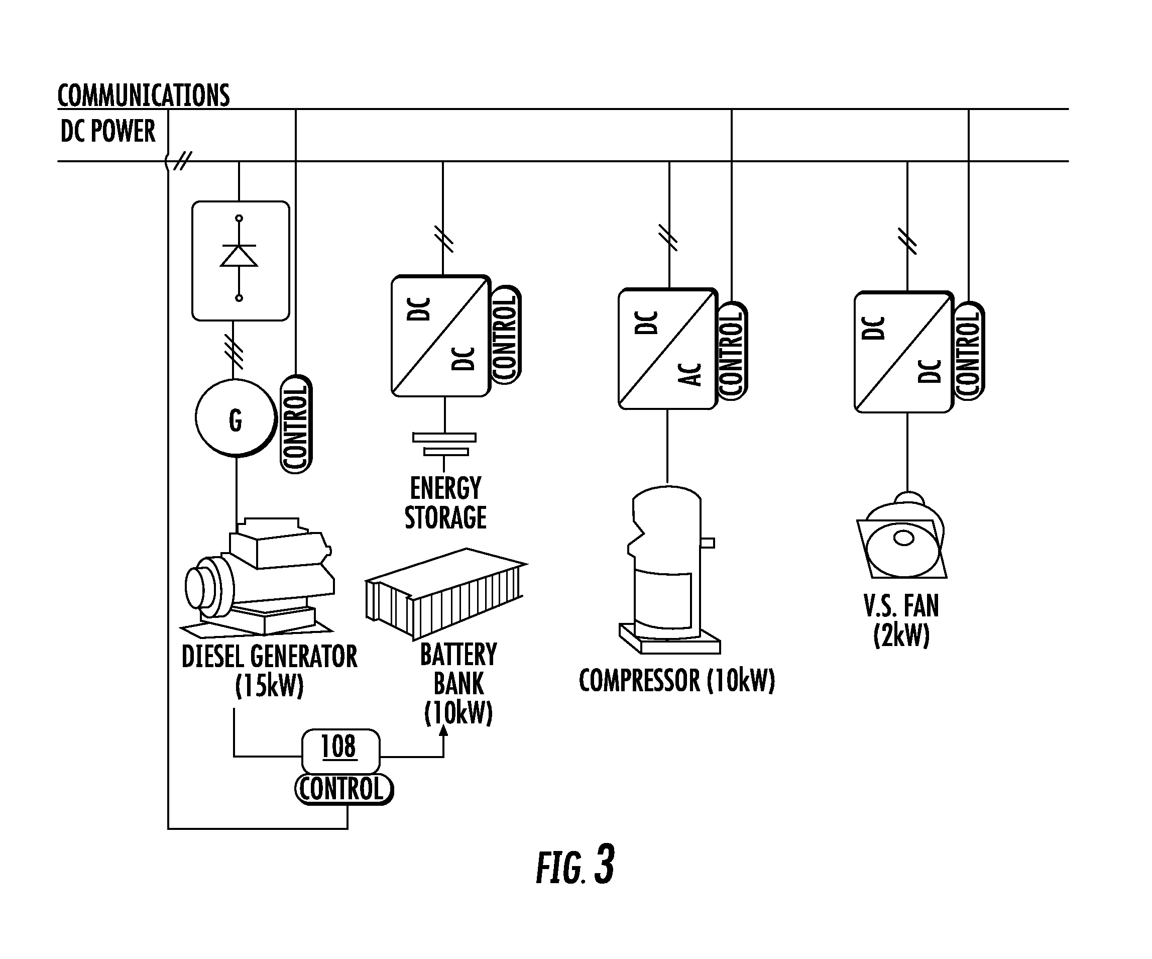
[0039] Referring to FIG. 2, the transport refrigeration unit 26 further includes a multiple energy source 50 configured to selectively power the compressor motor 60, the condenser fan motors 90, the evaporator fan motors 98, the controller 82, and other components 99 (see FIG. 3), which may include various solenoids and/or sensors. The power may be transferred over various buses and/or electrical conductors 106. The multiple energy source 50 may include an energy storage device 52, and a generator 54 mechanically driven by a combustion engine 56 that may be part of, and dedicated to, the transport refrigeration unit 26. The energy storage device 52 may be at least one battery or battery bank. In one embodiment, the energy storage device 52 may be secured to the underside of the bottom wall 32 of the trailer 24 (see FIG. 1). It is further contemplated and understood that other examples of the energy storage device 52 may include fuel cells, and other devices capable of storing and outputting electric power.
[0040] Referring to FIGS. 2 and 3, power management relative to the multiple energy source 50 and controlled power distribution relative to the various power loads may be configured/arranged to minimize the size of the combustion engine 56 and minimize fossil fuel consumption while still providing enough electric power to meet temperature pulldown demands of the operating transport refrigeration unit 26. The controller 82 through a series of data and command signals over various pathways 110 may, for example, control the electric motors 60, 90, 98 as dictated by the cooling needs of the refrigeration unit 26. The controller 82 may further control the electric power output of the generator 54 and the batteries 52 in order to meet the varying load demands of transport refrigeration unit 26.
[0041] In one example, the generator 54 and the battery or battery bank 52 may be electrically arranged in series. The electric power may be generally distributed through the bus 106, and may be direct current (DC). A converter (not shown) may be arranged at the outlet of the generator 54. The fan motors 90, 98 may be DC motors, and the compressor motor 60 may be an alternating current (AC) motor with an inverter (not shown) at the power input to the motor 60. In one example, the generator 54 may have a maximum power output of about 15 kW, the battery bank 52 may output electric power at about 10 kW, the steady state compressor motor 60 load may be about 10 kW, and the evaporator fan motor 98 and condenser fan motor 90 load may be about 2 kW. It is further contemplated and understood that various power conditioning devices may be configured throughout the transport refrigeration unit 26 depending upon the current type and voltage demands of any particular component.
[0042] In one embodiment, the generator 54 may be configured or downsized to provide substantially all of the electric power demands of the transport refrigeration unit 26 including the motors 60, 90, 98 during standard set point conditions (i.e., steady state conditions). However, when the transport refrigeration unit 26 is operating in a temperature pulldown state, the batteries 52 are available as a `battery boost` to increase or supplement the DC power through the bus 106 thereby satisfying the temporary increase in power demand of, for example, the compressor motor 60. In this embodiment, the voltage potential of the batteries 52 may be about 5 kW to 7 kW.
[0043] In another embodiment, the batteries 52 may be configured to provide substantially all of the electric power demands of the transport refrigeration unit 26 including the motors 60, 90, 98 during standard set point conditions (i.e., steady state conditions). However, when the transport refrigeration unit 26 is operating in a temperature pulldown state, the generator 54 is available as a `battery boost` to increase or supplement the DC power through the bus 106 thereby satisfying the temporary increase or surge in power demand of, for example, the compressor motor 60. In this embodiment, the voltage potential of the batteries 52 may be about 15 kW.
[0044] The transport refrigeration unit 26 may further include a battery charger 108 that may be powered by the generator 54 during part-load operating conditions of the transport refrigeration unit 26 (i.e., partial compressor load conditions), and controlled by the controller 82. The battery charger 108 may be controlled by the controller 82 and is configured to charge the batteries 52 when needed and during ideal operating conditions. By charging the batteries 52 during reduced compressor load conditions, the size and weight of the generator 54 and driving engine 56 may be minimized.
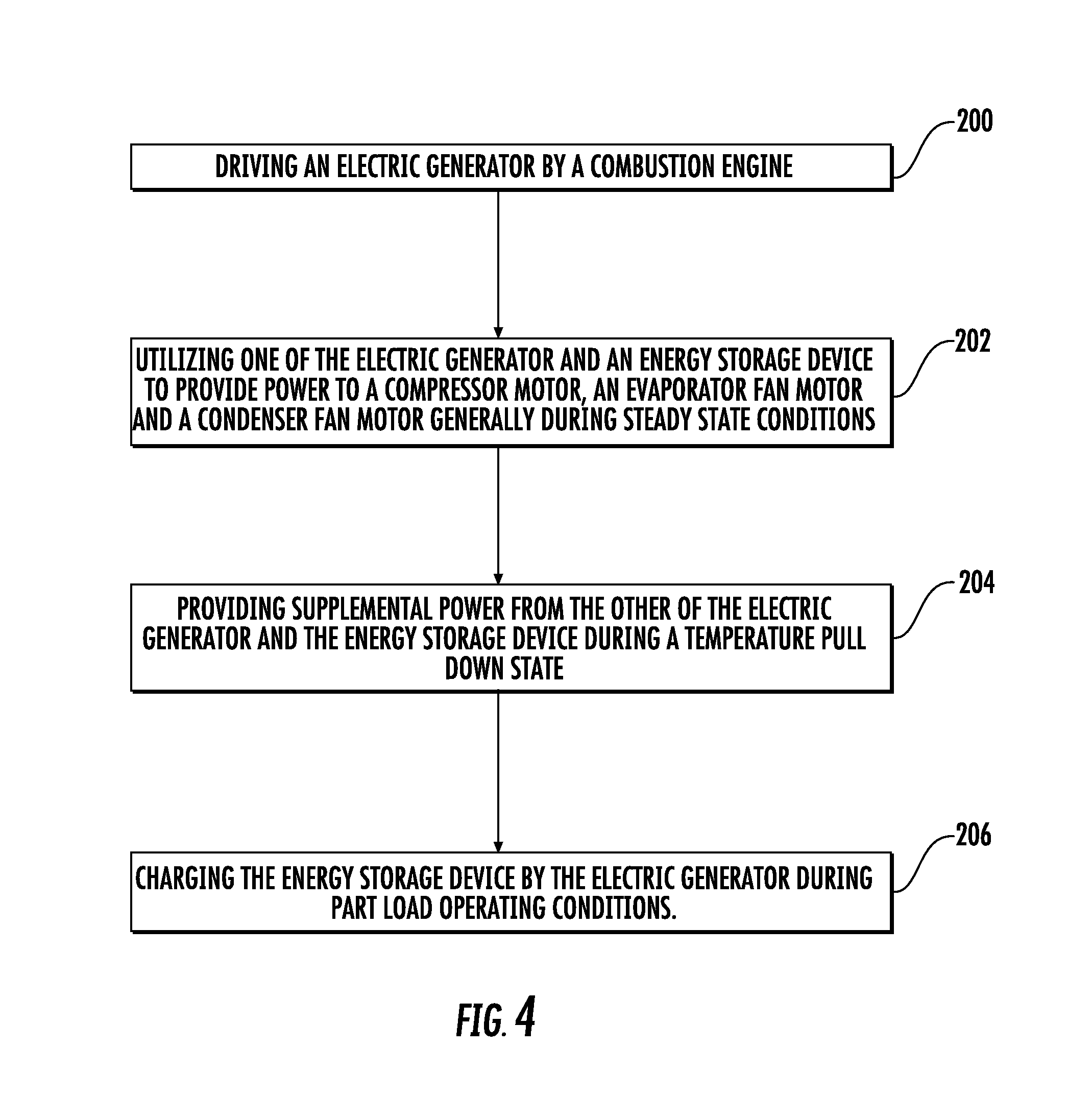
[0045] Referring to FIG. 4, a method of operating the transport refrigeration unit 26 may include a first block 200 of driving the electric generator 54 by the combustion engine 56. In block 202, the transport refrigeration unit 26 may utilize one of the electric generator 54 and the energy storage device 52 to provide power to the compressor motor 60, the evaporator fan motor 98, and the condenser fan motor 90 during steady state conditions. Per block 204, supplemental power may be provided by the other of the electric generator 54 and the energy storage device 52 during a temperature pull down state which may typically require more power than steady state conditions. In block 206, the energy storage device 52 may be recharged by the generator 54 during part load operating conditions of the transport refrigeration unit 26.
[0046] Benefits of the present disclosure when compared to more traditional transport refrigeration units include lower fuel consumption, and a refrigeration unit that may emit less noise and may be lighter in weight. Yet further, the present disclosure includes an energy storage device that is conveniently and efficiently recharged to meet the power demands of the refrigeration unit while meeting combustion engine power and emission requirements that may be enforced by regulatory/government agencies.
[0047] While the present disclosure is described with reference to the figures, it will be understood by those skilled in the art that various changes may be made and equivalents may be substituted without departing from the spirit and scope of the present disclosure. In addition, various modifications may be applied to adapt the teachings of the present disclosure to particular situations, applications, and/or materials, without departing from the essential scope thereof. The present disclosure is thus not limited to the particular examples disclosed herein, but includes all embodiments falling within the scope of the appended claims.
* * * * *
D00000
D00001
D00002
D00003
D00004
XML
uspto.report is an independent third-party trademark research tool that is not affiliated, endorsed, or sponsored by the United States Patent and Trademark Office (USPTO) or any other governmental organization. The information provided by uspto.report is based on publicly available data at the time of writing and is intended for informational purposes only.
While we strive to provide accurate and up-to-date information, we do not guarantee the accuracy, completeness, reliability, or suitability of the information displayed on this site. The use of this site is at your own risk. Any reliance you place on such information is therefore strictly at your own risk.
All official trademark data, including owner information, should be verified by visiting the official USPTO website at www.uspto.gov. This site is not intended to replace professional legal advice and should not be used as a substitute for consulting with a legal professional who is knowledgeable about trademark law.