Steam Generator Pipe Having A Turbulence Installation Body
Bruckner; Jan ; et al.
U.S. patent application number 16/089588 was filed with the patent office on 2019-04-25 for steam generator pipe having a turbulence installation body. This patent application is currently assigned to Siemens Aktiengesellschaft. The applicant listed for this patent is Siemens Aktiengesellschaft. Invention is credited to Jan Bruckner, Martin Effert.
| Application Number | 20190120482 16/089588 |
| Document ID | / |
| Family ID | 58664650 |
| Filed Date | 2019-04-25 |

| United States Patent Application | 20190120482 |
| Kind Code | A1 |
| Bruckner; Jan ; et al. | April 25, 2019 |
STEAM GENERATOR PIPE HAVING A TURBULENCE INSTALLATION BODY
Abstract
A steam generator pipe for producing a steam generator pipe with a spiral-shaped installation body, wherein an elevation extends on the inner side of the steam generation pipe in the axial direction of the steam generator pipe. A method for producing a steam generator pipe having an installation body.
| Inventors: | Bruckner; Jan; (Uttenreuth, DE) ; Effert; Martin; (Erlangen, DE) | ||||||||||
| Applicant: |
|
||||||||||
|---|---|---|---|---|---|---|---|---|---|---|---|
| Assignee: | Siemens Aktiengesellschaft Munich DE |
||||||||||
| Family ID: | 58664650 | ||||||||||
| Appl. No.: | 16/089588 | ||||||||||
| Filed: | April 19, 2017 | ||||||||||
| PCT Filed: | April 19, 2017 | ||||||||||
| PCT NO: | PCT/EP2017/059227 | ||||||||||
| 371 Date: | September 28, 2018 |
| Current U.S. Class: | 1/1 |
| Current CPC Class: | B21C 1/22 20130101; F22B 37/103 20130101 |
| International Class: | F22B 37/10 20060101 F22B037/10; B21C 1/22 20060101 B21C001/22 |
Foreign Application Data
| Date | Code | Application Number |
|---|---|---|
| Jul 7, 2016 | DE | 10 2016 212 416.1 |
Claims
1.-4. (canceled)
5. A method for producing a steam generator pipe having an installation body, the method comprising: producing a steam generator pipe having an elevation which extends in the longitudinal direction of the steam generator pipe on a pipe inner side, and welding the installation body on the elevation in the steam generator pipe.
6. The method as claimed in claim 5, wherein the steam generator pipe having an elevation is produced by cold drawing.
7. The method as claimed in claim 5, wherein the elevation is embossed using a stamp.
8. The method according to claim 5, wherein the installation body is spiral-shaped and is welded on the elevation at multiple contact points.
Description
CROSS REFERENCE TO RELATED APPLICATIONS
[0001] This application is the US National Stage of International Application No. PCT/EP2017/059227 filed Apr. 19, 2017, and claims the benefit thereof. The International Application claims the benefit of German Application No. DE 102016212416.1 filed Jul. 7, 2016. All of the applications are incorporated by reference herein in their entirety.
FIELD OF INVENTION
[0002] The invention relates to a method for producing a steam generator pipe having an installation body.
BACKGROUND OF INVENTION
[0003] Smooth pipes or internally ribbed pipes are used for evaporator heating surfaces in steam generators. The use of internally ribbed pipes may be necessary for various reasons: low full load mass flow density of the evaporator (for example BENSON low mass flux design), high heat flow density and risk of film boiling (for example drum-type boiler), avoidance of flow stratification in normal load operation (for example minimum load in evaporators with spiral pipes).
[0004] The internal ribbing of the pipes is produced by a cold drawing process according to the prior art. According to the current state of knowledge, internally ribbed pipes can be produced only with materials having a maximum chromium content of 5%. If it is necessary to use internally ribbed pipes composed of higher chromium alloyed steels, for example as a result of a further increase of the steam parameters, the internally ribbed pipes are not able to be produced with a consistently good quality using the production processes currently available.
[0005] Patent applications already made have proposed the replacement of the cold-drawn inner ribs by installation bodies. For example, the production and fitting of a swirl installation body in a smooth evaporator pipe is disclosed by WO 2011/151135 A2.
[0006] Furthermore, EP 2 390 567 A1 discloses a method for producing steam generator pipes, in which an installation body is fixed in grooves of a template shaft, the template shaft is inserted with the installation body into a steam generator pipe, the fixing of the installation body on the template shaft is released and the template shaft is removed from the steam generator pipe again.
[0007] Finally, DE 10 2012 219 898 B4 claims a resistance spot welding apparatus for fixing a swirl installation body on an inner wall of a steam generator pipe and discloses the application of the resistance spot welding method for producing a connection between the pipe and the installation body.
[0008] However, it is evident that there is a wide scatter of the quality of the welding results achieved with the resistance spot welding apparatus. The installation body has a high stiffness and it closely abuts the pipe inner wall to a large extent as soon as the template shaft has been screwed out of the pipe. However, the contact with the pipe wall is not provided with certainty at all locations owing to tolerances of the pipe and the installation body. Although the electrode of the welding lance presses, via a hydraulic cylinder, the wire of the installation body against the pipe inner wall already prior to the welding current being applied, it is not ensured that an electrically conductive contact surface between the installation body and the pipe inner side is produced precisely and only at the welding electrode.
SUMMARY OF INVENTION
[0009] It is an object of the invention to specify a method for producing a steam generator pipe having an insulation body.
[0010] The object directed at a method is achieved by a method for producing a steam generator pipe having an installation body, in which a steam generator pipe having an elevation which extends in the longitudinal direction of the steam generator pipe on a pipe inner side is produced, and the installation body is welded on the elevation in the steam generator pipe.
[0011] The invention is based on the finding that it is necessary for there to be a contact surface between the installation body and the pipe inner wall precisely at the welding electrode in order that a sufficiently good quality of the welding can be produced in a reproducible manner. According to the invention, it is therefore proposed that a relatively small elevation is produced on the pipe inner wall prior to the introduction of the swirl installation body, and that the welding of the installation body occurs precisely on this elevation.
[0012] The elevation gives rise to a defined location at which the local contact pressure by the electrode acts and at which the current flows during the welding.
[0013] The chromium content of the steam generator pipe is typically over 5%. In the case of steam generator pipes for steam generators having relatively large steam parameters, the use of steels having a chromium content of over 5% is necessary. Corresponding reliable production processes are not known, and so the additional effort for the provision of such a pipe having an elevation is justified.
[0014] The elevation is less than 1 mm in size in the radial direction in relation to the steam generator pipe. The elevation thus remains relatively small and essential merely has to compensate for production tolerances.
[0015] Here, it may be expedient for the steam generator pipe having an elevation to be produced by cold drawing. In a process on an industrial scale, it is thus possible for the particular form of the inner side to be integrated in a largely cost-neutral manner already in the production process of the semi-finished product.
[0016] It may alternatively be expedient for the elevation to be embossed using a stamp, in particular using a hydraulic stamp.
[0017] In both cases, elevations of a few tenths of a millimeter in size can thus be readily produced or embossed, on which the welding can then be realized with sufficient strength in the steam generator pipe.
[0018] In an advantageous embodiment of the invention, the installation body is spiral-shaped and is welded on the elevation at multiple points. In this way, it is possible, even for relatively larger steam parameters, for an internally ribbed steam generator pipe to be produced.
BRIEF DESCRIPTION OF THE DRAWINGS
[0019] The invention will be discussed in more detail by way of example on the basis of the drawings. In the drawings, in each case schematically and not to scale:
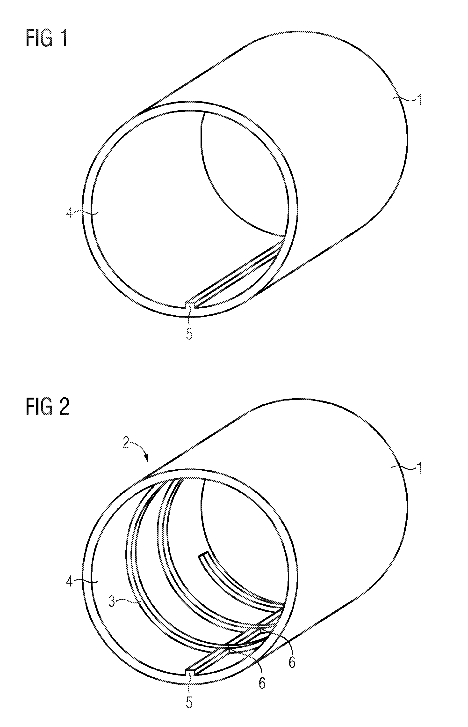
[0020] FIG. 1 shows a steam generator pipe with an elevation,
[0021] FIG. 2 shows a steam generator pipe with a spiral-shaped installation body, and
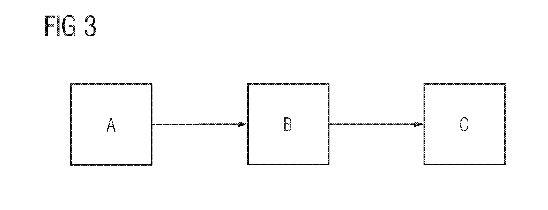
[0022] FIG. 3 shows a flow diagram of the method according to the invention.
DETAILED DESCRIPTION OF INVENTION
[0023] FIG. 1 shows, schematically and by way of example, a steam generator pipe 1 for the production of a steam generator pipe 2 having a spiral-shaped installation body 3, which is shown in FIG. 2.
[0024] On the inner side 4 of the steam generator pipe 1 in FIG. 1, an elevation 5 extends in the axial direction of the steam generator pipe 1, specifically, as FIG. 2 shows, over the entire region in which the spiral-shaped installation body 3 is arranged. The installation body 3 is welded to the elevation 5 at multiple contact points 6.
[0025] FIG. 3 schematically shows the individual steps of the production method according to the invention. In step A, a steam generator pipe 1 having an elevation which extends in the longitudinal direction of the steam generator pipe on a pipe inner side is produced, for example by means of cold drawing. The object in FIG. 1 is thus formed. The installation body 3 is then firstly introduced in step B and subsequently welded on the elevation 5 in the steam generator pipe 1 in step C, with the result that a steam generator pipe 2 having an installation body 3 is formed. Since a swirl installation body 3 shown in FIG. 2 has multiple windings, it is also welded at multiple contact points 6 between the swirl installation body 3 and the elevation 5.
* * * * *
D00000
D00001
D00002
XML
uspto.report is an independent third-party trademark research tool that is not affiliated, endorsed, or sponsored by the United States Patent and Trademark Office (USPTO) or any other governmental organization. The information provided by uspto.report is based on publicly available data at the time of writing and is intended for informational purposes only.
While we strive to provide accurate and up-to-date information, we do not guarantee the accuracy, completeness, reliability, or suitability of the information displayed on this site. The use of this site is at your own risk. Any reliance you place on such information is therefore strictly at your own risk.
All official trademark data, including owner information, should be verified by visiting the official USPTO website at www.uspto.gov. This site is not intended to replace professional legal advice and should not be used as a substitute for consulting with a legal professional who is knowledgeable about trademark law.