Controlled high pressure steam generation system
Vandigriff; John Edward ; et al.
U.S. patent application number 15/732319 was filed with the patent office on 2019-04-25 for controlled high pressure steam generation system. The applicant listed for this patent is Einar Arvid Orbeck, JR., John Edward Vandigriff. Invention is credited to Einar Arvid Orbeck, JR., John Edward Vandigriff.
| Application Number | 20190120480 15/732319 |
| Document ID | / |
| Family ID | 66171049 |
| Filed Date | 2019-04-25 |
| United States Patent Application | 20190120480 |
| Kind Code | A1 |
| Vandigriff; John Edward ; et al. | April 25, 2019 |
Controlled high pressure steam generation system
Abstract
A controlled steam generation system for producing and controlling high temperature and high pressure steam includes a steam generator, a control unit for controlling the temperature and pressure of the steam, a power unit for supplying power to the steam unit through the control unit, and a water source and pump for supplying water to the steam unit, the water pump being controlled by the control unit.
| Inventors: | Vandigriff; John Edward; (Carrollton, TX) ; Orbeck, JR.; Einar Arvid; (Las Vegas, NV) | ||||||||||
| Applicant: |
|
||||||||||
|---|---|---|---|---|---|---|---|---|---|---|---|
| Family ID: | 66171049 | ||||||||||
| Appl. No.: | 15/732319 | ||||||||||
| Filed: | October 24, 2017 |
| Current U.S. Class: | 1/1 |
| Current CPC Class: | F22B 29/06 20130101; F22B 1/282 20130101; F22B 35/104 20130101; F22D 5/18 20130101 |
| International Class: | F22B 1/28 20060101 F22B001/28; F22D 5/18 20060101 F22D005/18; F22B 29/06 20060101 F22B029/06; F22B 35/10 20060101 F22B035/10 |
Claims
1. A controlled steam generation system for producing and controlling high temperature and high pressure steam, comprising a steam generator which includes a housing and at least two electrodes around which is continuous flow of water, a control unit for controlling the temperature and pressure of the steam, a power unit for supplying power to the steam unit through the control unit, and a water source and pump for supplying the continuous flow of water to the steam unit, the water pump being controlled by the control unit.
2. The controlled steam generation system according to claim 1, wherein the system includes pressure and a temperature measuring devices for measuring the output pressure and temperature of the generated steam and directing the pressure and temperature measurements of the steam into the control unit.
3. The controlled steam generation system according to claim 1, including a water filter to allow the use of impure water such as brine water and other water containing contaminants to filter and remove particulate materials.
4. The controlled steam generation system according to claim 1, wherein steam is produced by moving high pressure water flow into the steam unit where it surrounds and passes electrical elements to which voltage is applied, the voltage producing a constant current between the electrical elements and turning the water into steam.
5. The controlled steam generation system according to claim 1, including a one way value through which the water is sent into the steam unit to prevent a back flow of water and steam into the water pump.
6. The controlled steam generation system according to claim 1, wherein the steam unit has an internal insulation of ceramic to prevent electrical contact between electrical elements in the steam unit and the outer metallic housing of the steam unit.
7. The steam unit of claim 6, wherein the electrical elements extend from the inside of the steam unit to the outside of the steam unit through the metallic housing and are insulated from there to prevent power supplied to the electrical elements from contacting the metallic housing.
8. A controlled steam generation system for producing and controlling high temperature and high pressure steam, comprising a steam generator which includes a housing and at least two electrodes around which is continuous flow of water, a control unit for controlling the temperature and pressure of the steam, a power unit for supplying power to the steam unit through the control unit, and a water source and pump for supplying the continuous flow of water to the steam unit, the water pump being controlled by the control unit, a one way valve to prevent the steam and water in the steam generator from flowing back into the water pump and water source.
9. The controlled steam generation system according to claim 8, including steam pressure and temperature measuring meters for measuring the steam pressure and temperature output of the steam generator.
10. The controlled steam generation system according to claim 9, wherein the measurement of the pressure and temperature of the high pressure steam output is returned to the control unit to regulate the temperature and pressure of the steam out of the steam generation unit.
11. A controlled steam generation system for producing and controlling high temperature and high pressure steam, comprising a steam generator, a control unit for controlling the temperature and pressure of the steam, a power unit for supplying power to the steam unit through the control unit, and a water source and pump for supplying a continuous flow of high pressure water to the steam unit, the water pump being controlled by the control unit, the steam generator having an outer metallic structure, with an inner ceramic insulation, a plurality of electrical elements, an input in which the pressurized water flows into the steam unit and an output out of which the steam flows, steam being produced when electrical power is applied to the electrical elements and water flowing around the electrical elements is converted to steam.
12. The controlled steam generation system according to claim 11, wherein one of DC voltage, single phase voltage and three phase voltage is used to convert the water flow around the electrical elements into steam.
13. The controlled steam generation system according to claim 4, wherein the electrical elements are mounted within the steam unit parallel to each other, spaced apart and extend across the steam unit within the flow of water.
14. The controlled steam generation system according to claim 4, wherein the electrical elements are mounted within the steam unit parallel to each other and spaced apart and alone the length of the steam unit along the flow of water.
Description
FIELD OF THE INVENTION
[0001] The invention relates to steam generation systems and more particularly to a controlled steam generation system for producing and controlling high temperature and high pressure steam.
BACKGROUND OF THE INVENTION
[0002] Steam generation systems generally have a boiler in which water is heated to produce steam. New technology uses electrodes to which a voltage is applied to heat the water in which the electrodes are placed to produce steam. Such an apparatus is described in U.S. Pat. No. 7,403,701 in which water is heated using electrodes placed in the water. A similar system to heat water and produce steam is described in U.S. Pat. No. 3,584,193. Another U.S. Pat. No. 4,266,116 uses a water flow system to produce steam. In this system the water is pumped through a porous insulating material positioned between two electrodes. The electrodes are connected to a power sources to heat the electrodes to produce steam.
SUMMARY OF THE INVENTION
[0003] The present invention relates to a controlled steam generation system, and more particularly to a high pressure high temperature system which produces extremely high pressure and high temperature steam. The high pressure high temperature steam can be used in cleaning oil wells, producing power with turbines, the purification of water.
[0004] The technical advance represented by the invention as well as the objects thereof will become apparent from the following description of a preferred embodiment of the invention when considered in conjunction with the accompanying drawings, and the novel features set forth in the appended claims.
BRIEF DESCRIPTION OF THE DRAWINGS
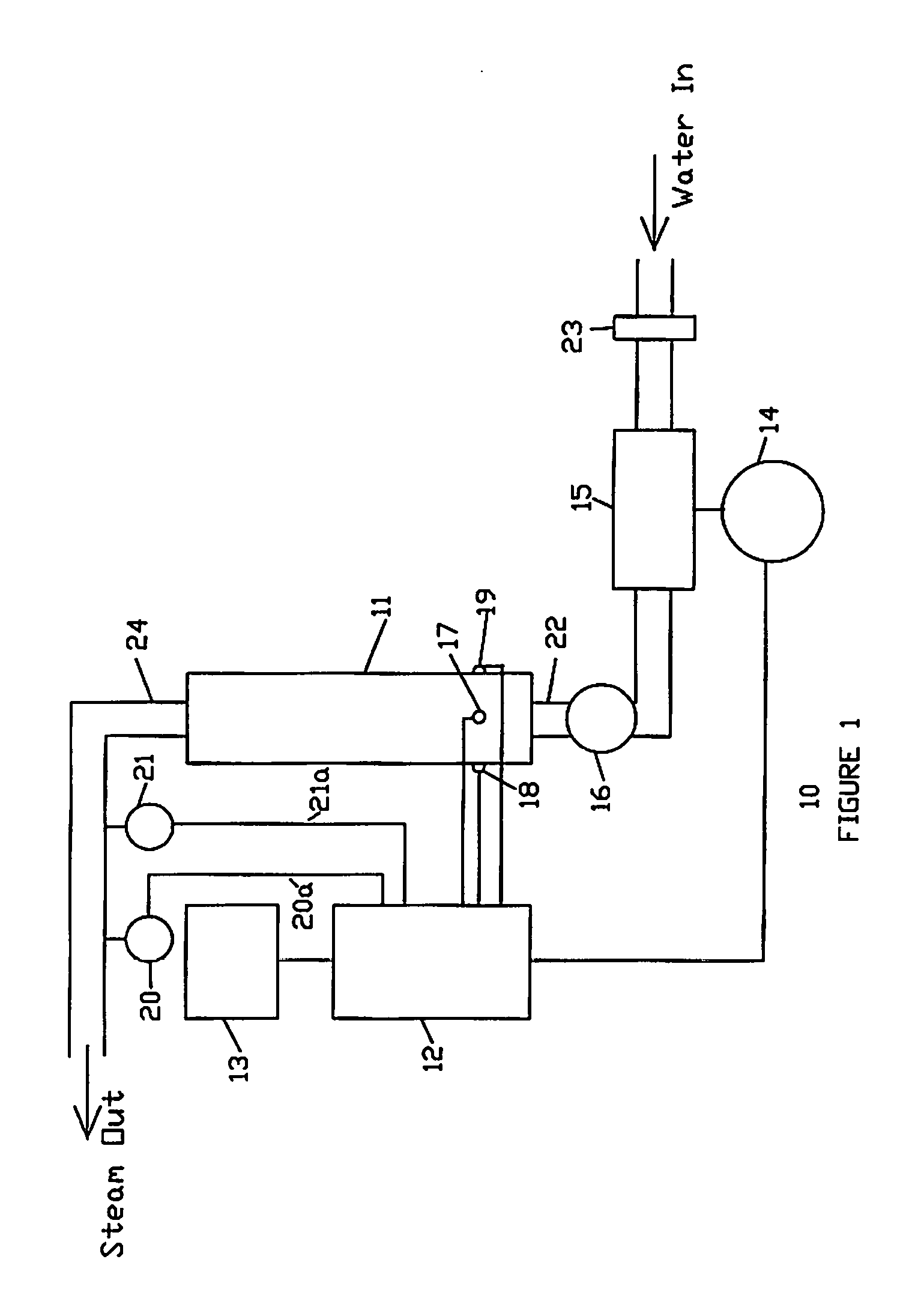
[0005] FIG. 1 illustrates the controlled steam generation system in which the pressure and temperature of the steam is controlled and regulated by a control unit.
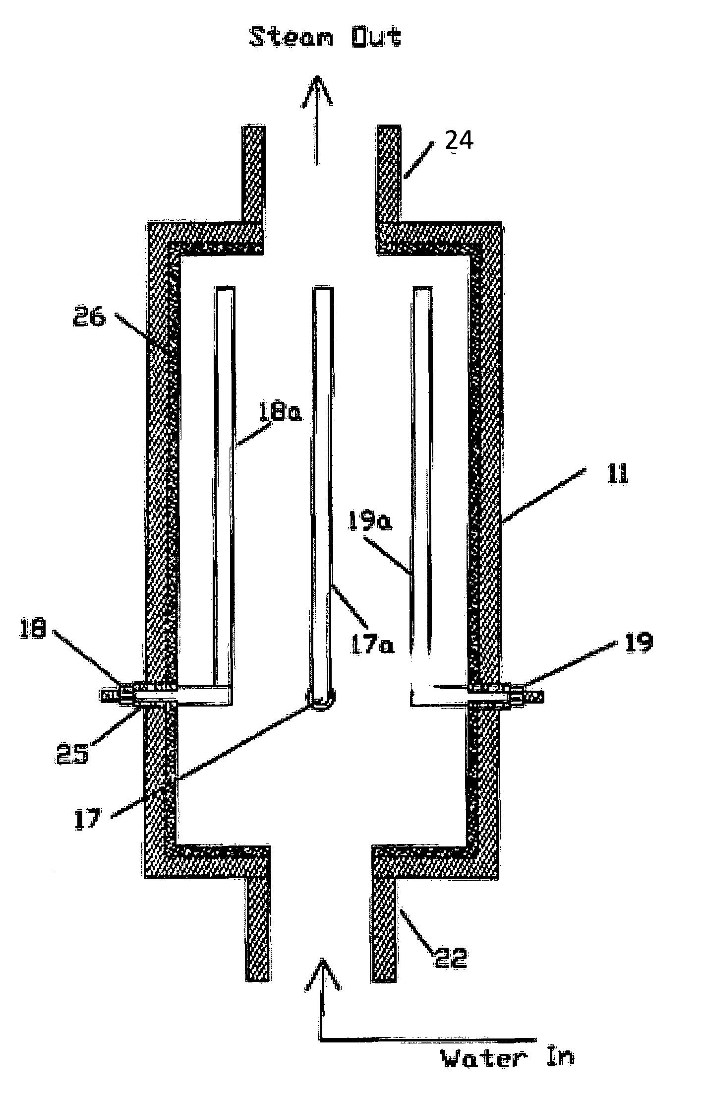
[0006] FIG. 2 illustrates one example of the steam generator.
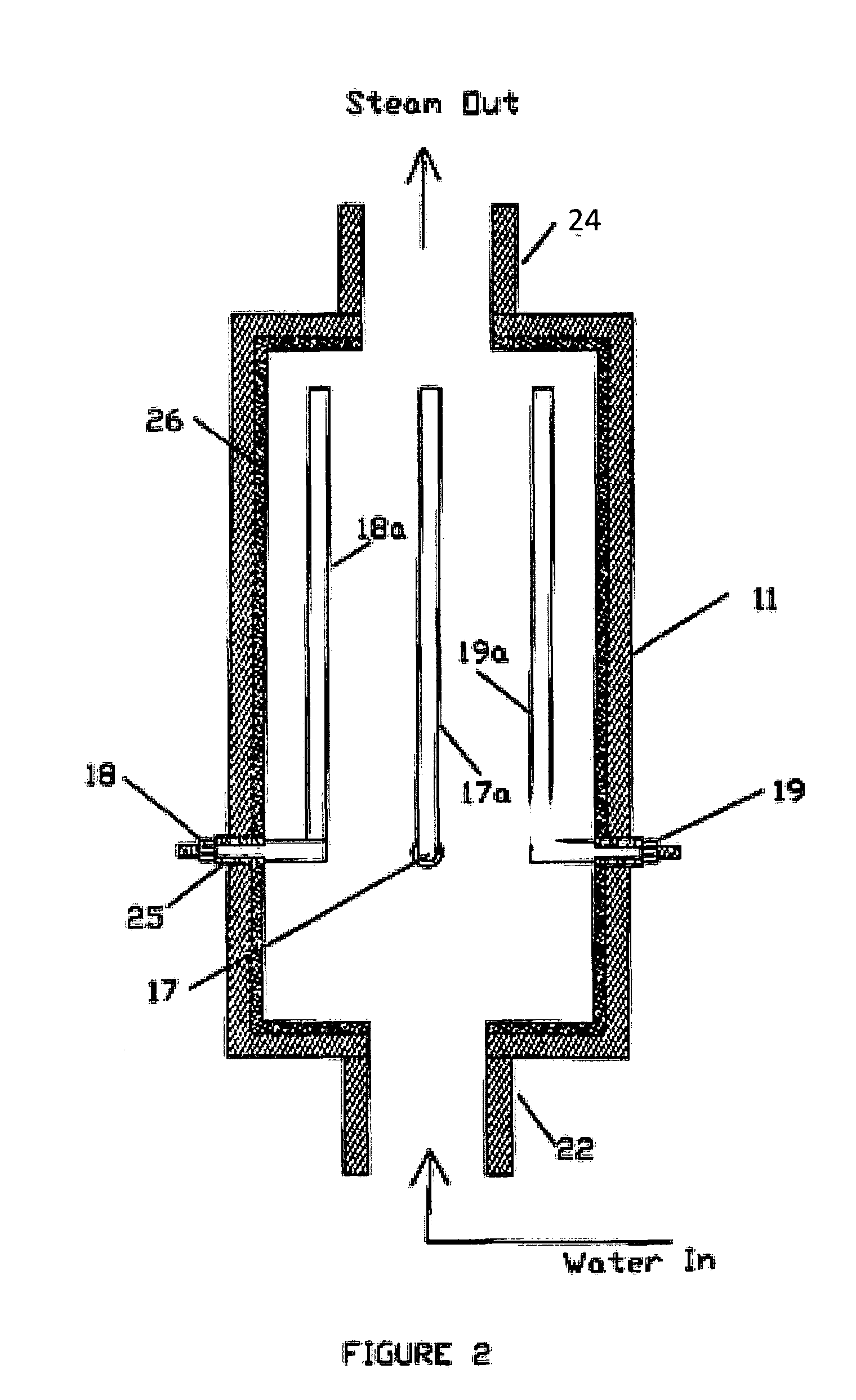
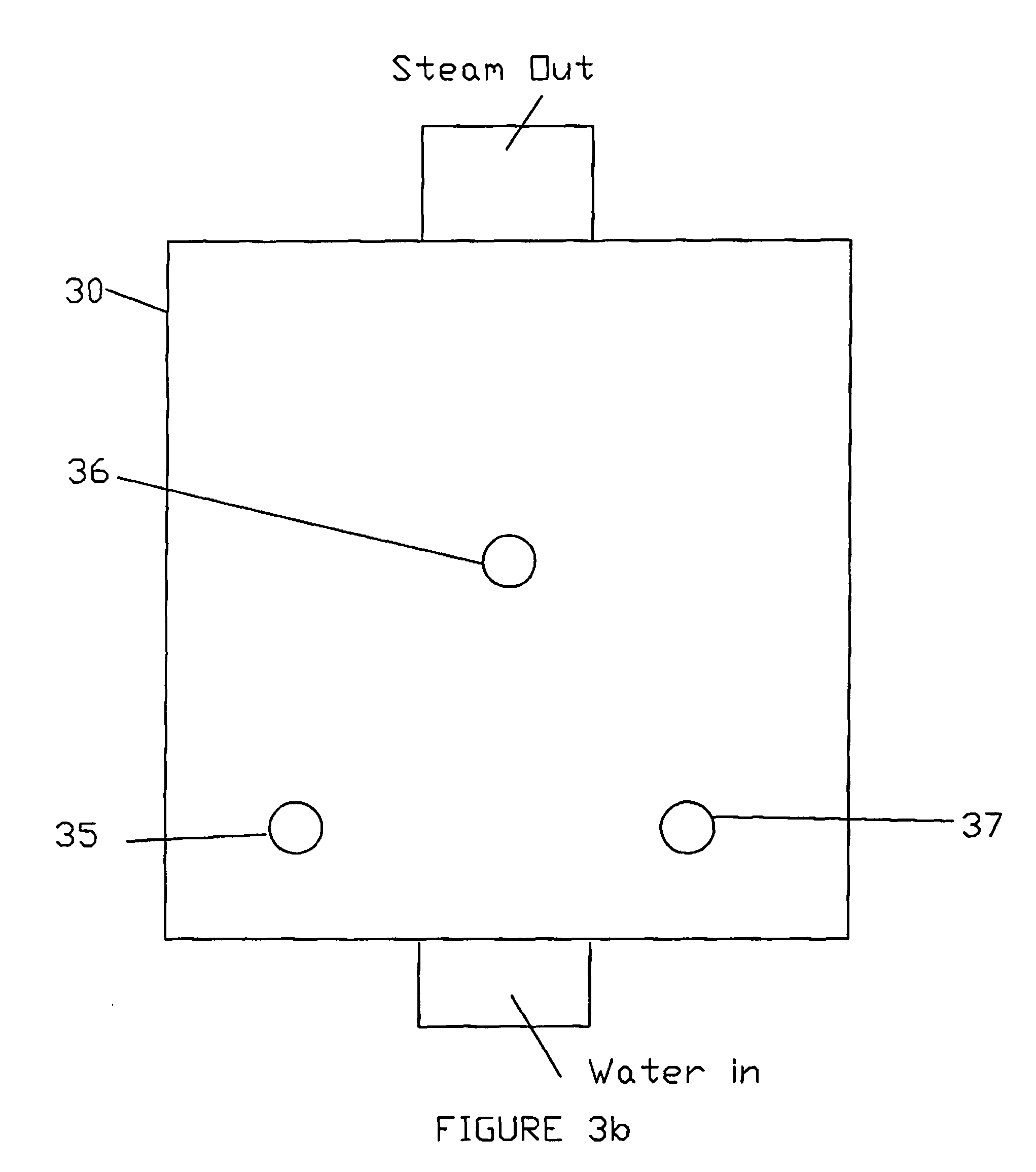
[0007] FIGS. 3a and 3b illustrate a second configuration of the placement of the electrical elements.
DESCRIPTION OF A PREFERRED EMBODIMENT
[0008] In FIG. 1, the controlled pressure steam generation unit 10 has a steam generator 11 which is powered at terminals 17, 18 and 19. This unit is powered through a control unit 12 which supplies voltage to the terminals 17, 18 and 19. The illustrated unit 11 is powered by a three phase voltage. The unit 11 could be powered by one of 12 volts DC, 120 volts ac single phase, 240s volt AC single phase, 208s AC volt 3-phase and 480 volts AC 3-phase. When single phase voltage is used, only two terminals are needed to supply power to the steam unit 11. The power applied and voltage applied depends upon the desired pressure and temperature of the out put steam. The steam generated can be in a range of ambient temperature to well over 760 degree Fahrenheit. The output pressure range can be from about 14.7 psi to well over 4500 psi.
[0009] To produce steam, power comes from a power source 13 which goes through control unit 12 and then to steam unit 11, applying voltage to terminals 17, 18 and 19. Water is input at 22. The water comes from any source of water and is strained by stainer 23 to remove any particulate material. A pump 15, controlled by motor 14 feeds the water through one way valve 16 and inlet 22 into the steam generator where the power applied to terminals 17, 18 and 19 coverts the water to steam. Steam exits out output 24. A temperature gauge 21 measures the temperature of the steam, and a pressure gauge 20 measures the pressure of the steam. Both the temperature 21a and pressure 20a is feed back to the control unit 12. The control unit is preprogrammed to the desired temperature and pressure settings. The control unit 12 also controls motor 14 which drives the water pump 15. By controlling the motor speed, the amount of water pumped into the steam unit 11, the pressure of the steam output is controlled. The control of the motor 14 from the control unit 12 is based upon, in part, the pressure information 20a from the pressure gage 20 returned to the control unit 12.
[0010] The steam system of FIG. 1 is not large like steam boilers which have to be housed in a large apace. The steam system of the present invention can be stationary or mounted on a trailer and moved to any location where steam is needed or used.
[0011] The present system can use impure water sources such as gray water, brine water, sewage water naturally occurring saline bodies of water. It can use clean water, but in some areas, clean water is limited or not available. Fracturing water from wells may be used, particularly when the steam unit is used to clean old wells. These impure water sources provide a better water to use in the steam unit as the impurities in the water provide more conductivity and provide a more efficient production of steam.
[0012] In regard to the power source 13 for the steam generation system, a portable generator may be used to supply the power to initially start the generation of steam. A steam driven turbine (not illustrated), which turns a generator, may be used after the initial start up of the steam generator. Upon start, the steam generator requires a larger amount of power until the steam generator has started producing steam. After the steam has reached it desired temperature and pressure, the amount of power required decreases. This results from the fact that once the current flowing through the water starts producing steam, the conductivity of the steam is less than the water, and the amount of current to maintain the desired flow of steam reduces. In a small initially produced steam unit the steam, using 220 Volt AC, the current was initially about 45 amps. After the steam flow was produced, the current fell to about 15 amps to maintain the desired flow of steam.
[0013] FIG. 2 shows the basic structure of a steam generation unit that can be used in the present invention. Steam unit 11 has a metal outer wall which is basically tubular in form and has one end 22 into which there is a continuous flow of water. The opposite end 24 is from which the steam exits. The inner surface of the steam unit 11 is insulated with a layer of ceramic 26 to prevent electrical contact of the outer metal wall. The electrical elements 17a, 18a and 19a are vertically placed within the steam unit and extend through the outer metal wall and are insulated from contacting the metal wall by ceramic cylinders 25. The steam unit of FIG. 2 shows three electrical elements. With three electrical elements, a three phase voltage would be used. If there were only two electrical elements, then a single phase voltage would be used.
[0014] An important feature of the present invention is that a continuous flow of pressurized water is used. In the prior art steam generators, a container holds water and two electrical elements are at least partially emerged in the container of water. The container is supplied additional water as needed, but there is not continuous flow of pressurized water.
[0015] FIG. 3a shows a different configuration and placement of the electrical elements 35, 36 and 37. In this configuration, the electrical elements are placed across the water flow in the steam generation unit. The steam unit housing 39 has an inner ceramic insulation 31. The electrical elements 35, 36 and 37 each extend through the steam unit wall and are insulted by ceramic insulator 38, 39 and 40 to insulate the electrical elements from the housing 30.
[0016] FIG. 3b illustrated how the electrical elements 35, 36 and 37 are spaced as they are mounted through the wall 30 of the steam unit. The spacing of the electrical elements in FIG. 2 and FIGS. 3a and 3b are such that there will be not arcing from the power applied to the electrical elements. There will only be flow of current through the water in the steam unit between each of the electrical elements.
* * * * *
D00000
D00001
D00002
D00003
D00004
XML
uspto.report is an independent third-party trademark research tool that is not affiliated, endorsed, or sponsored by the United States Patent and Trademark Office (USPTO) or any other governmental organization. The information provided by uspto.report is based on publicly available data at the time of writing and is intended for informational purposes only.
While we strive to provide accurate and up-to-date information, we do not guarantee the accuracy, completeness, reliability, or suitability of the information displayed on this site. The use of this site is at your own risk. Any reliance you place on such information is therefore strictly at your own risk.
All official trademark data, including owner information, should be verified by visiting the official USPTO website at www.uspto.gov. This site is not intended to replace professional legal advice and should not be used as a substitute for consulting with a legal professional who is knowledgeable about trademark law.