Downhole Communication Valve And Method Of Use
NICHOLS; Mark B.
U.S. patent application number 16/220455 was filed with the patent office on 2019-04-25 for downhole communication valve and method of use. The applicant listed for this patent is COLT PETROLEUM TECHNOLOGY, LLC. Invention is credited to Mark B. NICHOLS.
| Application Number | 20190120015 16/220455 |
| Document ID | / |
| Family ID | 57944180 |
| Filed Date | 2019-04-25 |

| United States Patent Application | 20190120015 |
| Kind Code | A1 |
| NICHOLS; Mark B. | April 25, 2019 |
DOWNHOLE COMMUNICATION VALVE AND METHOD OF USE
Abstract
A downhole communication valve containing a piston and chamber which allows hydrostatic testing of a casing or tubing string multiple times before permanently opening communication ports to the exterior.
| Inventors: | NICHOLS; Mark B.; (Mineral Wells, TX) | ||||||||||
| Applicant: |
|
||||||||||
|---|---|---|---|---|---|---|---|---|---|---|---|
| Family ID: | 57944180 | ||||||||||
| Appl. No.: | 16/220455 | ||||||||||
| Filed: | December 14, 2018 |
Related U.S. Patent Documents
| Application Number | Filing Date | Patent Number | ||
|---|---|---|---|---|
| 15225928 | Aug 2, 2016 | 10184318 | ||
| 16220455 | ||||
| 62201391 | Aug 5, 2015 | |||
| Current U.S. Class: | 1/1 |
| Current CPC Class: | E21B 34/10 20130101 |
| International Class: | E21B 34/10 20060101 E21B034/10 |
Claims
1. A downhole valve comprising: a. A tubular housing. b. A tubular mandrel. c. A sleeve. d. A locking apparatus. e. A filling apparatus.
2. The downhole valve of claim 1 wherein a sealed chamber is formed which may be filled with a compressible gas.
3. The downhole valve of claim 1 wherein the pressure in said sealed chamber holds a sleeve in the closed position until its pressure is overcome by the pressure tending to move the sleeve to the open position.
4. The downhole valve of claim 1 wherein the traverse rate of said sleeve is limited or determined by the rate of flow through an orifice or restrictor.
5. The downhole valve of claim 1 which has 3 primary positions: a. Closed wherein communication is not permitted between the interior and exterior of the valve. b. Open wherein communication is permitted between the interior and exterior of the valve. c. Open and locked wherein communication is permanently permitted between the interior and exterior of the valve.
Description
CROSS-REFERENCE TO RELATED APPLICATIONS
[0001] This application is a continuation application of U.S. patent application Ser. No. 15/225,928, filed Aug. 2, 2016, which claims benefit of U.S. Provisional Patent Application Ser. No. 62/201,391, filed Aug. 5, 2015, which is herein incorporated by reference.
FIELD OF THE INVENTION
[0002] The present invention generally relates to drilling and related equipment as typically used in the oil and gas industry. More specifically, the present invention relates to a valve that may be installed within a casing or tubing string and its method of use.
BACKGROUND OF THE INVENTION
[0003] A valve which provides flow ports between the internal and external portions that are selectively isolated until a successful integrity test of the casing or tubing string is completed. Hydrostatic pressure applied to the internal portion of the tool causes shifting of an internal piston which compresses gasses until a limit is reached which permanently opens the valve.
[0004] Said valve may be conversely used in any application in which hydrostatic pressure is the preferred or only available method of opening a valve.
BRIEF DESCRIPTION OF THE DRAWINGS
[0005] FIG. 1 is an elevated view of a multi-cycle communication valve in accordance with a preferred embodiment.
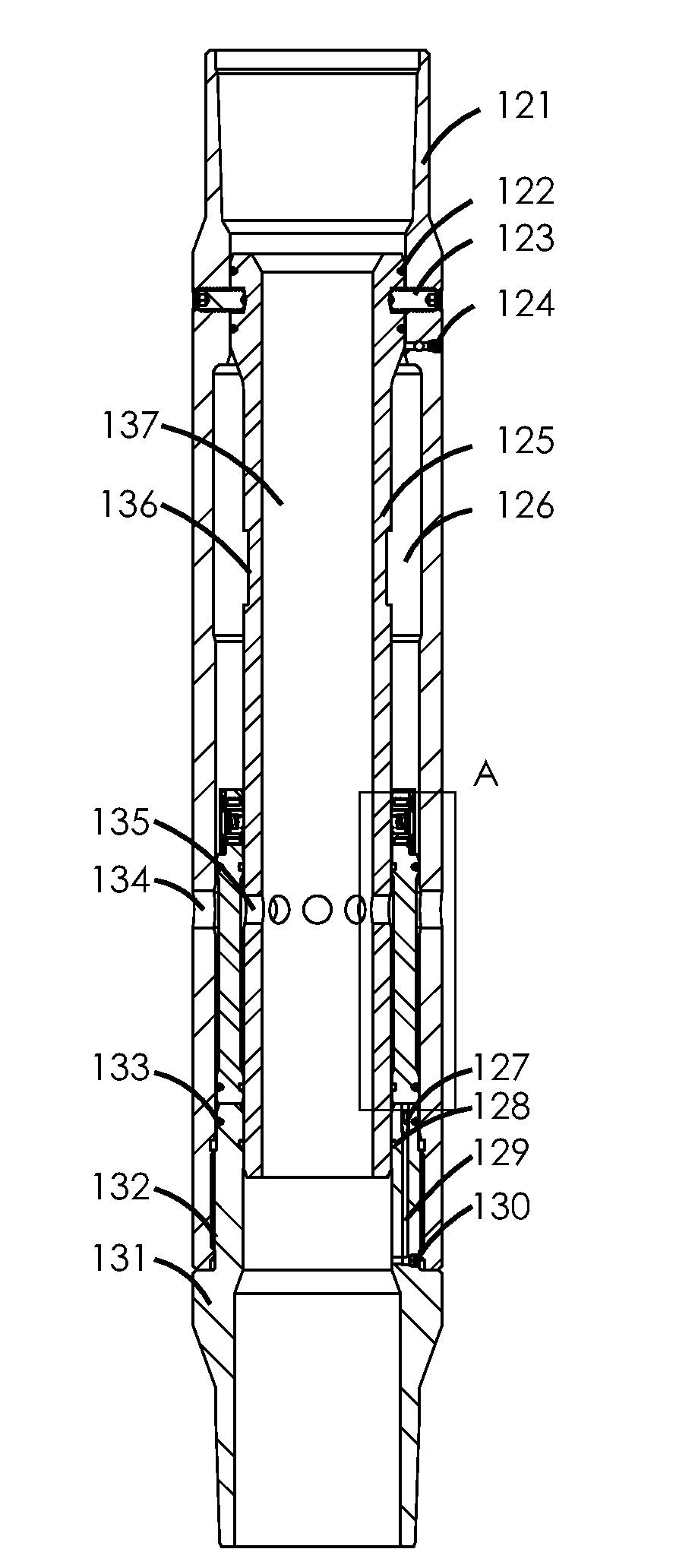
[0006] FIG. 2 is a section view of a closed multi-cycle communication valve in accordance with a preferred embodiment.
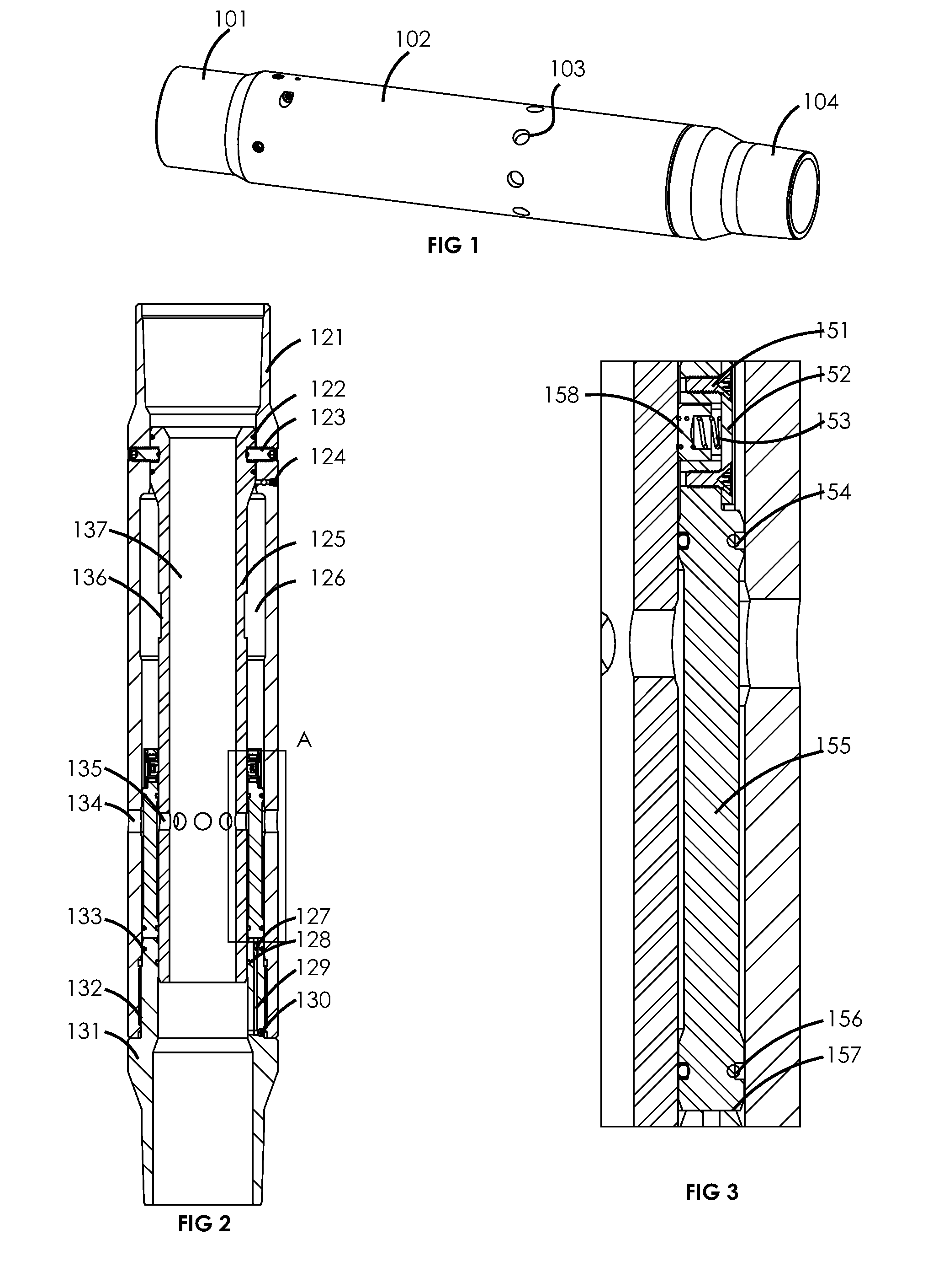
[0007] FIG. 3 is a detail view of the portion designated as "A" of FIG. 2.
[0008] FIG. 4 is a section view of an opened and locked multi-cycle communication valve in accordance with a preferred embodiment.
[0009] FIG. 5 is a detail view of the portion designated as "B" of FIG. 4.
[0010] FIG. 6 is a detail view of a filling apparatus in the closed position as shown along the line "C-C" of FIG. 4.
[0011] FIG. 7 is a detail view of a filling apparatus in the filling position as shown along the line "C-C" of FIG. 4.
DETAIL DESCRIPTIONS OF THE INVENTION
[0012] All illustrations of the drawings are for the purpose of describing selected versions of the present invention and are not intended to limit the scope of the present invention.
[0013] Referring to FIGS. 1-7 there is provided a multi-cycle communication valve in accordance with a preferred embodiment. As used herein, the terms "a" or "an" shall mean one or more than one. The term "plurality" shall mean two or more than two. The term "another" is defined as a second or more. The terms "including" and/or "having" are open ended (e.g. comprising). The term "or" as used herein is to be interpreted as inclusive meaning one or any combination. Terms such as "upper" and "lower" are in reference to respective positions within the drawings and do not necessarily denote a physical configuration or orientation. Reference herein to "one embodiment", "certain embodiments", "an embodiment" or similar terms means that a particular feature or characteristic described in connection with the embodiment is included in at least one embodiment of the present disclosure. Thus the appearances of such phrases in various places throughout this specification are not necessarily all referring to the same embodiment. Furthermore, the particular features or characteristics may be combined in any suitable manner on one or more embodiments without limitation.
[0014] Generally in a preferred embodiment, the multi cycle communication valve is externally comprised of a housing 102, a lower sub 104 which preferably includes a threaded joint for connection to the lower portion of the casing or tubing string, a plurality of flow ports 103 which may be circular, slotted or of any shape to provide adequate flow area and a means of connection to upper portion of the casing or tubing string 101. The multi-cycle communication valve selectively permits fluid transfer to occur between the interior and exterior via the ports 103.
[0015] A mandrel 125 is preferably disposed within the bore of the housing 121. Said mandrel may be secured in place with a plurality of screws 123 or by any other acceptable means such as a locking shoulder or a threaded joint. The mandrel preferably provides a bore 137 for the transmission of fluids through the interior to lower portions of the casing or tubing string. The mandrel also preferably provides a plurality of ports 135 which may selectively provide communication between the mandrel's bore 137 and the exterior of the valve via ports provided in the housing 134.
[0016] A sleeve 155 is preferentially disposed within the annulus between the mandrel and the housing 121. Upper sleeve seals 154 and mandrel seals 122 create a chamber 126 which may be pre-filled with a gas or liquid via a filling apparatus 124.
[0017] An end sub 131 is preferably secured to the housing 121 via a threaded connection 132 thus further restraining the interior components.
[0018] Said sleeve 155 may provide a locking feature which is preferably comprised by a plurality of keys 158, springs 153, plates 152 and screws 151. Said spring 153 preferentially is compressed inward by said springs 153. Said spring 153 is kept in compression by the installation of a said cover plate 152 and screws 151. The surface of the mandrel does not allow extension until said key is aligned with a groove in the mandrel 136 thus allowing locking up the keys against a shoulder 211.
[0019] The aforementioned filling apparatus 124 may be more generally comprised of intersecting holes 224 and 225, a straight plug 221 with seals 222, a semi-permanent plug 223 and another plug 226. In one configuration, the straight plug 221 is partially withdrawn. Gas or liquid may be filled into the aforementioned chamber 126 via the open passageway 227. Once filling has completed, the straight plug 221 may be inserted such that the seals 222 stop flow from the chamber 126 to the exterior. The plug 226 may be subsequently installed for redundancy.
[0020] It will be obvious to one skilled in the art that many such filling arrangements could be used. An alternative is a simple check valve.
[0021] Once the chamber 126 is filled to a pre-determined pressure, the sleeve 155 will be forced in the closed direction unless the pressure acting on the sleeve's lower face 157 exceeds the pressure in the chamber 126. If the pressure on the lower face 157 exceeds the pressure in the chamber 126, the sleeve will begin to traverse away from the end sub 131.
[0022] A second chamber will be formed by the movement of the sleeve 155. This chamber is defined as the annulus between the mandrel 125 and housing 121 longitudinally constrained between the sleeve 151 and the end sub 131. The chamber is isolated by the end sub seals 133 and 128 and the lower sleeve seals 155. Flow of fluids is permitted into this void or chamber via a series of holes 129. Said holes may be intersecting for manufacturability in which case one or more may be sealed with a plug 130. Flow through these holes is restricted or metered by an insert or orifice 127. The metering of flow controls the speed of the traverse rate of the sleeve 155.
[0023] In use, a preferred embodiment of the valve is first assembled and then pre-filled with air or nitrogen as previously described. This pressure may depend on many factors such as well conditions, desired delay time, etc. The valve is then run into the well. To perform a pressure integrity test, pressure on the interior of the casing may be raised to an identified target. This pressure may be held for a period of time before the valve opens. If for any reason, the test is desired to be terminated, the valve may be returned to its original configuration if it has not been fully locked. Therefore, testing may be performed multiple times if desired.
[0024] When it is desired to permanently open the valve, a pressure is applied to the interior of the casing or tubing. This pressure is identified by a variety of means but is typically less than the previously mentioned test pressure. If this pressure is held for a sufficient period of time, the valve will first open where the sleeve 155 traverses such that the mandrel ports 135 and the housing ports 134 allow communication with the exterior. The sleeve may then be closed if pressure is relieved or if pressure is maintained, the valve may be placed in the locked position as previously described. If placed in the locked position, the sleeve will permanently allow communication between the ports and thus between the exterior and the interior.
[0025] Although the invention has been explained in relation to its preferred embodiment, it is to be understood that many other possible modifications and variations can be made without departing from the spirit and scope of the invention.
* * * * *
D00000
D00001
D00002
XML
uspto.report is an independent third-party trademark research tool that is not affiliated, endorsed, or sponsored by the United States Patent and Trademark Office (USPTO) or any other governmental organization. The information provided by uspto.report is based on publicly available data at the time of writing and is intended for informational purposes only.
While we strive to provide accurate and up-to-date information, we do not guarantee the accuracy, completeness, reliability, or suitability of the information displayed on this site. The use of this site is at your own risk. Any reliance you place on such information is therefore strictly at your own risk.
All official trademark data, including owner information, should be verified by visiting the official USPTO website at www.uspto.gov. This site is not intended to replace professional legal advice and should not be used as a substitute for consulting with a legal professional who is knowledgeable about trademark law.