Modular Window Mill Assembly And Method
Hulsewe; Ewoud
U.S. patent application number 15/788112 was filed with the patent office on 2019-04-25 for modular window mill assembly and method. This patent application is currently assigned to Baker Hughes, a GE company, LLC. The applicant listed for this patent is Ewoud Hulsewe. Invention is credited to Ewoud Hulsewe.
| Application Number | 20190120005 15/788112 |
| Document ID | / |
| Family ID | 66169198 |
| Filed Date | 2019-04-25 |


| United States Patent Application | 20190120005 |
| Kind Code | A1 |
| Hulsewe; Ewoud | April 25, 2019 |
MODULAR WINDOW MILL ASSEMBLY AND METHOD
Abstract
A modular window mill assembly includes a mill body having a first connection feature and a second connection feature; a mill head having a cutting structure and an engagement feature, the engagement feature configured to matingly engage with the first connection feature of the mill body to replaceably secure the mill head to the mill body; and, a blade having a cutting structure and a coupling feature, the coupling feature of each blade respectively matingly coupled to the second connection feature to replaceably secure the blade to the mill body. The mill body, mill head, and the blade are formed separately from each other prior to assemblage together to form the window mill assembly.
| Inventors: | Hulsewe; Ewoud; (Woodlands, TX) | ||||||||||
| Applicant: |
|
||||||||||
|---|---|---|---|---|---|---|---|---|---|---|---|
| Assignee: | Baker Hughes, a GE company,
LLC Houston TX |
||||||||||
| Family ID: | 66169198 | ||||||||||
| Appl. No.: | 15/788112 | ||||||||||
| Filed: | October 19, 2017 |
| Current U.S. Class: | 1/1 |
| Current CPC Class: | E21B 29/06 20130101; E21B 29/005 20130101; E21B 17/02 20130101 |
| International Class: | E21B 29/06 20060101 E21B029/06; E21B 29/00 20060101 E21B029/00; E21B 17/02 20060101 E21B017/02 |
Claims
1. A modular window mill assembly comprising: a mill body having a first connection feature and a second connection feature; a mill head having a cutting structure and an engagement feature, the engagement feature configured to matingly engage with the first connection feature of the mill body to replaceably secure the mill head to the mill body; and a blade having a cutting structure and a coupling feature, the coupling feature of each blade respectively matingly coupled to the second connection feature to replaceably secure the blade to the mill body; wherein the mill body, mill head, and the blade are formed separately from each other prior to assemblage together to form the window mill assembly.
2. The modular window mill assembly of claim 1, wherein the mill body includes a longitudinal axis, a first end and a longitudinally spaced second end, the mill head disposed at the first end of the mill body, and the blade longitudinally trapped by the mill head and a shoulder between the first and second ends of the mill body.
3. The modular window mill assembly of claim 1, wherein the first connection feature is threadably engaged with the engagement feature.
4. The modular window mill assembly of claim 1, wherein the engagement feature includes a male portion receivable within a female portion of the first connection feature.
5. The modular window mill assembly of claim 1, wherein the second connection feature includes circumferentially spaced slots extending from a first longitudinal end of the mill body.
6. The modular window mill assembly of claim 5, wherein a radial outermost end of the slots are narrower than a radial interior portion of the slots.
7. The modular window mill assembly of claim 5, wherein the slots are dove-tail shaped or T-shaped.
8. The modular window mill assembly of claim 5, wherein the mill body has a shoulder wall disposed between the first end of the mill body and a second end of the mill body, the slots extending from the first end of the mill body to the shoulder wall.
9. The modular window mill assembly of claim 1, wherein the mill head is secured to the first end of the mill body through weldless engagement between the engagement feature and the first connection feature, and the blade is secured to the mill body through weldless coupling between the coupling feature of the blade and the second connection feature.
10. The modular window mill assembly of claim 1, wherein the cutting structure of the mill head and the blade includes carbide and/or polycrystalline diamond compact inserts.
11. The modular window mill assembly of claim 1, wherein the mill head includes a plurality of rows of cutting structures, each row aligned with cutting structures on a plurality of the blades when the blades and the mill head are secured to the mill body.
12. The modular window mill assembly of claim 1, further comprising a fluid flow path extending along a longitudinal axis of the mill body.
13. A system comprising: the modular window mill assembly of claim 1; a string, the window mill assembly attached to an end of the string; and, a tubular structure, the string and window mill assembly passable through an interior of the tubular structure and the window mill assembly rotatable by the string within the tubular structure.
14. The system of claim 13, further comprising a whipstock within the tubular structure, the whipstock having a guide surface, and the window mill assembly configured to slide along the guide surface to cut an opening in the tubular structure.
15. A method of assembling a modular window mill assembly, the method comprising: utilizing a mill body having a first connection feature and a second connection feature; matingly coupling the blade having a cutting structure with the second connection feature of the mill body; and matingly engaging a mill head having a cutting structure with the first connection feature.
16. The method of claim 15, wherein coupling the blade with the second connection feature of the mill body includes sliding the blade within a slot in the mill body.
17. The method of claim 16, wherein engaging the mill head with the first connection feature occurs subsequent to sliding the blade within the respective slot in the mill body, and longitudinally trapping the blade between the mill head and a shoulder wall of the mill body.
18. The method of claim 15, wherein the mill body includes a first end, the first connection feature includes a female portion indented from the first end, and the mill head includes a male portion received within the female portion.
19. The method of claim 15, wherein the mill head is threadably engaged to the first connection feature.
20. The method of claim 15, further comprising attaching the window mill head assembly to a string, the string configured to rotate the window mill assembly.
Description
BACKGROUND
[0001] In the resource recovery industry, resources (such as hydrocarbons, steam, minerals, water, metals, etc.) are often recovered from boreholes in formations containing the targeted resource. It is sometimes desired to cut a window in a downhole well casing, for the purpose of exiting the casing, to drill a lateral well bore off of the main bore. A window mill carried on, and rotated by, a work string is used to cut the window by penetrating the casing wall as it is guided therethrough by a guide surface of a whipstock. During use, the cutting surfaces of the window mill experience vibration and impact against the casing which can lead to their deterioration during this process. To reduce deterioration, materials that exhibit wear resistance while cutting through metal have been incorporated into the window mills.
[0002] The art would be receptive to improved and/or alternative window mills and methods for manufacturing improved and/or alternative window mills.
SUMMARY
[0003] A modular window mill assembly includes a mill body having a first connection feature and a second connection feature; a mill head having a cutting structure and an engagement feature, the engagement feature configured to matingly engage with the first connection feature of the mill body to replaceably secure the mill head to the mill body; and, a blade having a cutting structure and a coupling feature, the coupling feature of each blade respectively matingly coupled to the second connection feature to replaceably secure the blade to the mill body. The mill body, mill head, and the blade are formed separately from each other prior to assemblage together to form the window mill assembly.
[0004] A method of assembling a modular window mill assembly includes utilizing a mill body having a first connection feature and a second connection feature; matingly coupling the blade having a cutting structure with the second connection feature of the mill body; and, matingly engaging a mill head having a cutting structure with the first connection feature.
BRIEF DESCRIPTION OF THE DRAWINGS
[0005] The following descriptions should not be considered limiting in any way. With reference to the accompanying drawings, like elements are numbered alike:
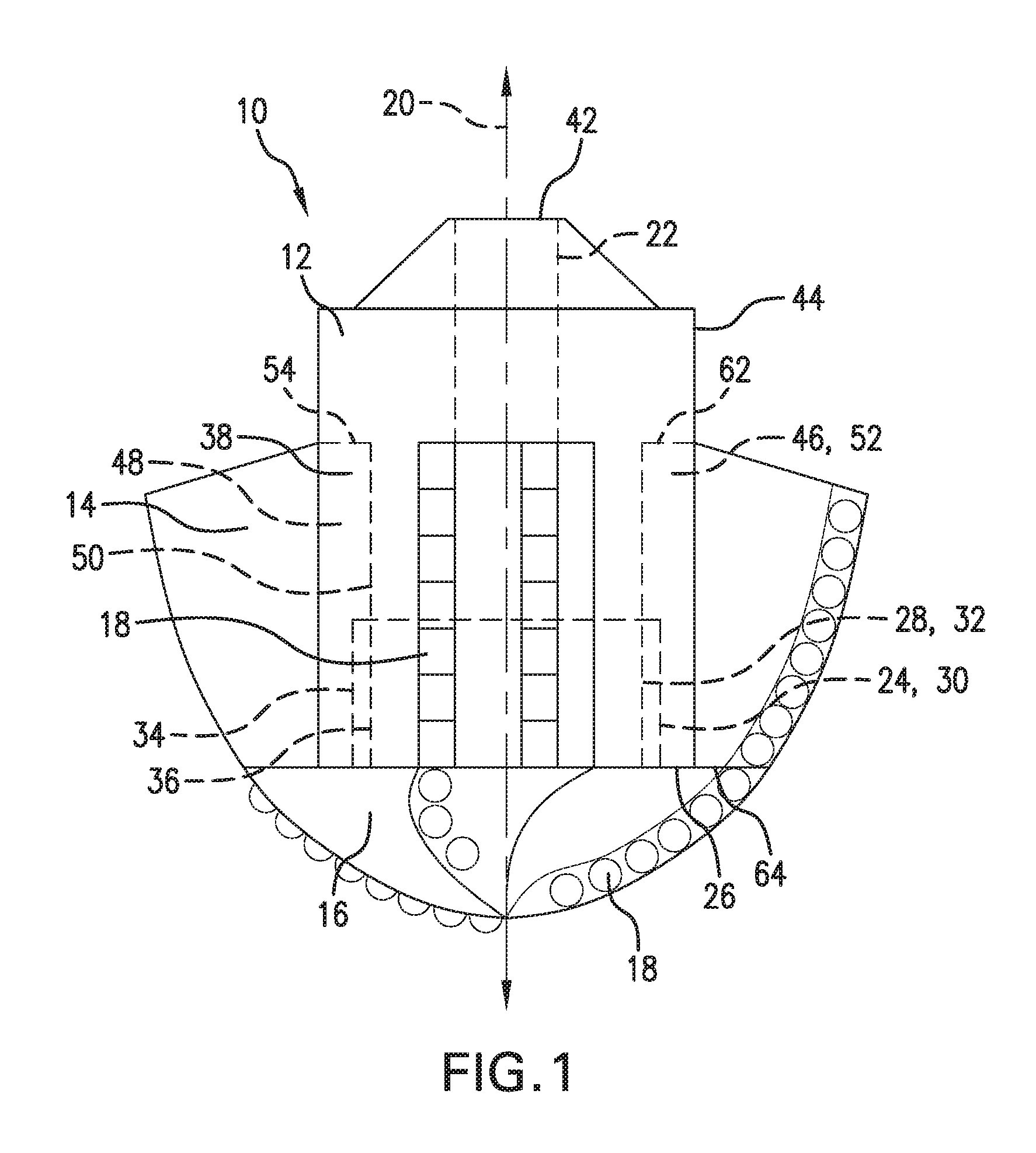
[0006] FIG. 1 depicts a side view of an embodiment of a modular window mill assembly;
[0007] FIG. 2 depicts a side view of an embodiment of a mill body for the window mill assembly of FIG. 1;
[0008] FIG. 3 depicts a side view of an embodiment of a replaceable blade for the window mill assembly of FIG. 1;
[0009] FIG. 4 depicts a side view of an embodiment of a replaceable mill head for the window mill assembly of FIG. 1;
[0010] FIG. 5 depicts a cross-sectional view of an embodiment of the millbody of FIG. 2;
[0011] FIG. 6 depicts a cross-sectional view of another embodiment of the mill body of FIGS. 2; and
[0012] FIG. 7 depicts a schematic view of the modular window mill assembly of FIG. 1 within a casing.
DETAILED DESCRIPTION
[0013] A detailed description of one or more embodiments of the disclosed apparatus and method are presented herein by way of exemplification and not limitation with reference to the Figures.
[0014] With reference now to FIGS. 1-6, a modular window mill assembly 10 is illustrated according to some embodiments. The window mill assembly 10 is a modular device and includes a mill body 12, a plurality of replaceable blades 14, and a replaceable mill head 16. At least the blades 14 and the mill head 16 include and can be pre-manufactured with a plurality of cutting structures 18 made of very hard material such as, but not limited to, one or more of polycrystalline diamond compact structure, carbide, inserts, and/or dressed with fixed cutters. The cutting structures 18 are provided on outer surfaces of each blade and oriented to cut through a casing 104 (FIG. 7) as the window mill assembly 10 is rotated by a work string 102 (FIG. 7). The outermost edges of the cutting structures 18 together establish a contour which is radially outside the outer contour of the blades 14 and the mill head 16 themselves.
[0015] With reference to FIGS. 1 and 2, the mill body 12 includes a longitudinal axis 20 which also defines an axis of rotation for the window mill assembly 10. In some embodiments, a flow path 22 may be provided along the longitudinal axis 20. The flow path 22 may be in fluidic communication with ports (not shown) on the exterior surface of the mill body 12, the mill head 16, and/or the blades 14 so that fluid can be pumped to the exterior of the window mill assembly 10. The mill body 12 further includes a first connection feature 24 which is configured to secure the mill head 16 to the mill body 12. The first connection feature 24 is provided at a first end 26 of the mill body 12, which corresponds to a downhole end of the mill body 12 during use. The mill head 16, shown separately in FIG. 4, includes an engagement feature 28 configured to mate with the first connection feature 24 of the mill body 12. The mill head 16 is dressed with cutting structures 18 for milling purposes. In the illustrated embodiment, the first connection feature 24 includes a female portion 30 indented into the first end 26 of the mill body 12, and the engagement feature 28 includes a male portion 32. The female portion 30 is sized to receive and retain the male portion 32. The female portion 30 may include interior threads 34, which threadingly receive the exterior threads 36 of the male portion 32 of the mill head 16. Thus, in the illustrated embodiment the mill head 16 is a mushroom-shaped cap retainer that can be threaded in the mill body 12 to secure the assembly 10. In alternate embodiments, the mill body 12 may include a male portion receivable within a female portion of the mill head 16. Alternate mechanical connections between the mill body 12 and the mill head 16 may be included that can removably retain the mill head 16 onto the first end 26 of the mill body 12, such as, but not limited to, bolted connections or one or more additional separate connection features utilized to connect the first connection feature 24 of the mill body 12 to the engagement feature 28 of the mill head 16.
[0016] The mill body 12 includes a second end 40 longitudinally spaced from the first end 26. The second end 40 of the mill body 12 is configured for attached to a string 102 (FIG. 7), as will be further described below. A blade receiving section 42 extends from the first end 26 of the mill body 12. With further reference to FIGS. 5 and 6, an outer circumference 44 of the mill body 12 includes a plurality of second connection features 46 which are configured to removably secure the plurality of blades 14, respectively, to the mill body 12. Each blade, as shown in FIG. 3, includes a coupling feature 48 located at the radially inward side 50 of the blade 14, substantially opposite a radially outermost side 57 of the blade 14. The coupling feature 48 is sized and configured to be retained within the second connection feature 46 during rotation of the window mill assembly 10. In the illustrated embodiments, the second connection feature 46 includes a slot 52 forming a pocket that extends from the first end 26 and ending at a shoulder wall 54 disposed between the first and second ends 26, 40 of the mill body 12. FIG. 5 depicts one embodiment of the slots 52 having a dovetail shape, and FIG. 6 depicts another embodiment of the slots 52 having a T-shape. The radial outermost side 56 of the slots 52 is narrower than a radially interior portion 58 of the slots 52 so as to retain the coupling features 48 of the blades 14 within the slots 52 during rotation of the window mill assembly 10 through use of adjacent pairs of circumferential slot ends 60 at the radial outermost side 56. The coupling features 48 of the blades 14 includes a corresponding T-shaped or dovetail shape, or other corresponding shape receivable within the slots 52 and conducive for blade retention during rotation. The number of blades 14 and corresponding slots 52 may be changed depending on application and size of the window mill assembly 10. For illustrative purposes only, five slots 52 are shown in FIG. 5 for receipt of five blades 14, and four slots 52 are shown in FIG. 6 for receipt of four blades 14. Also, while the slots 52 are shown extending substantially in parallel with the longitudinal axis 20 of the mill body 12, the slots 52 could instead be angled with respect to the longitudinal axis 20.
[0017] Insertion of the blades 14 within the slots 52 is by sliding the coupling features 48 into the slots 52 at the first end 26 of the mill body 12, and sliding the blades 14 towards the second end 40 of the mill body 12 until a second end 62 of the blade 14 contacts the shoulder wall 54. A longitudinal length of the coupling features 48 of the blades 14 may be substantially the same as a longitudinal length of the slots 52 so as to prevent longitudinal shifting of the blades 14 relative to the mill body 12. In such an embodiment, a first end 64 of the blades 14 is substantially aligned with the first end 26 of the mill body 12. After the blades 14 are inserted within the slots 52, the mill head 16 is secured to the first end 26 of the mill body 12 through the use of the first connection feature 24 of the mill body 12 and the engagement feature 28 of the mill head 16, As in the illustrated embodiment, after the blades 14 are slid into the slots 52 of the mill body 12, the mill head 16 is screwed into the mill body 12. The blades 14 are then longitudinally trapped within the mill body 12 between the shoulder wall 54 and the mill head 16. The blades 14 are radially trapped within the mill body 12 by the adjacent pairs of circumferential slot ends 60. Thus, the blades 14 are prohibited from moving radially and longitudinally with respect to the mill body 12 and mill head 16 when assembled together. In some embodiments, once the mill assembly 10 is assembled, respective rows of cutting structures 18 on the mill head 16 are aligned with cutting structures 18 on a respective blade 14.
[0018] Referring to FIG. 7, one embodiment for utilizing the window mill assembly 10 within a downhole system 100 is shown. For clarity, the cutting structures 18 are not illustrated in FIG. 7. The window mill assembly 10 is attached to a work string 102 and run through an interior of a tubular structure, such as a casing 104. A whipstock 106 is seated within the casing 104 and includes a guide surface 108 which is azimuthally oriented in the desired direction for guiding the mill assembly 10 to exit the casing 104. The guide surface 108 is angled at a first acute angle relative to a longitudinal axis of the casing 104. The longitudinal axis 20 of the mill body 12 may be initially parallel to the longitudinal axis of the casing 104, but will be angled relative to the longitudinal axis 20 of the casing 104 when the window mill assembly 10 is guided by the guide surface 108 of the whipstock 106 towards the casing 104. The cutting structures 18 on the mill head 16 and replaceable blades 14 are angled away from the hard guide surface 108 of the whipstock 106. As the window mill assembly 10 is rotated by the work string 102, the mill head 16 of the window mill assembly 10 moves in the downhole direction 110 (opposite an uphole direction 112) along the guide surface 108, causing the cutting structures 18 on the blades 14 to contact and mill through a wall 114 of the casing 104 to form window 116. Eventually, the cutting structures 18 on the mill head 16 also contact and mill through the casing 104.
[0019] The window mill assembly 10 and its cutting structures 18 can include materials that require strict welding procedures, and therefore maintaining and fixing window mills at a wellsite without the removable blades 14 and mill head 16 would require onsite specialty welding and local expertise. However, the window mill assembly 10 described herein has interchangeable blades 14 and mill head 16 so that the requirements for local welding can be reduced, and controls for welding procedures can be more strictly enforced at manufacturing facilities where the replaceable blades 14 and mill head 16 are pre-manufactured. The assembly of the blades 14 and mill head 16 to the mill body 12 to form the window mill assembly 10 can be assembled on-site, or pre-assembled and delivered to the site. Upon completion of a milling procedure, the mill head 16 and blades 14 can be replaced or discarded as needed at a lesser expense as compared to replacing an entire mill assembly 10.
[0020] Set forth below are some embodiments of the foregoing disclosure:
[0021] Embodiment 1: A modular window mill assembly including a mill body having a first connection feature and a second connection feature; a mill head having a cutting structure and an engagement feature, the engagement feature configured to matingly engage with the first connection feature of the mill body to replaceably secure the mill head to the mill body; and, a blade having a cutting structure and a coupling feature, the coupling feature of each blade respectively matingly coupled to the second connection feature to replaceably secure the blade to the mill body; wherein the mill body, mill head, and the blade are formed separately from each other prior to assemblage together to form the window mill assembly.
[0022] Embodiment 2: The modular window mill assembly as in any prior embodiment or combination of embodiments, wherein the mill body includes a longitudinal axis, a first end and a longitudinally spaced second end, the mill head disposed at the first end of the mill body, and the blade longitudinally trapped by the mill head and a shoulder between the first and second ends of the mill body.
[0023] Embodiment 3: The modular window mill assembly as in any prior embodiment or combination of embodiments, wherein the first connection feature is threadably engaged with the engagement feature.
[0024] Embodiment 4: The modular window mill assembly as in any prior embodiment or combination of embodiments, wherein the engagement feature includes a male portion receivable within a female portion of the first connection feature.
[0025] Embodiment 5: The modular window mill assembly as in any prior embodiment or combination of embodiments, wherein the second connection feature includes circumferentially spaced slots extending from a first longitudinal end of the mill body.
[0026] Embodiment 6: The modular window mill assembly as in any prior embodiment or combination of embodiments, wherein a radial outermost end of the slots are narrower than a radial interior portion of the slots.
[0027] Embodiment 7: The modular window mill assembly as in any prior embodiment or combination of embodiments, wherein the slots are dove-tail shaped or T-shaped.
[0028] Embodiment 8: The modular window mill assembly as in any prior embodiment or combination of embodiments, wherein the mill body has a shoulder wall disposed between the first end of the mill body and a second end of the mill body, the slots extending from the first end of the mill body to the shoulder wall.
[0029] Embodiment 9: The modular window mill assembly as in any prior embodiment or combination of embodiments, wherein the mill head is secured to the first end of the mill body through weldless engagement between the engagement feature and the first connection feature, and the blade is secured to the mill body through weldless coupling between the coupling feature of the blade and the second connection feature.
[0030] Embodiment 10: The modular window mill assembly as in any prior embodiment or combination of embodiments, wherein the cutting structure of the mill head and the blade includes carbide and/or polycrystalline diamond compact inserts.
[0031] Embodiment 11: The modular window mill assembly as in any prior embodiment or combination of embodiments, wherein the mill head includes a plurality of rows of cutting structures, each row aligned with cutting structures on a plurality of the blades when the blades and the mill head are secured to the mill body.
[0032] Embodiment 12: The modular window mill assembly as in any prior embodiment or combination of embodiments, further comprising a fluid flow path extending along a longitudinal axis of the mill body.
[0033] Embodiment 13: A system including: the modular window mill assembly as in any prior embodiment or combination of embodiments; a string, the window mill assembly attached to an end of the string; and, a tubular structure, the string and window mill assembly passable through an interior of the tubular structure and the window mill assembly rotatable by the string within the tubular structure.
[0034] Embodiment 14: The system as in any prior embodiment or combination of embodiments, further including a whipstock within the tubular structure, the whipstock having a guide surface, and the window mill assembly configured to slide along the guide surface to cut an opening in the tubular structure.
[0035] Embodiment 15: A method of assembling a modular window mill assembly, the method including: utilizing a mill body having a first connection feature and a second connection feature; matingly coupling the blade having a cutting structure with the second connection feature of the mill body; and, matingly engaging a mill head having a cutting structure with the first connection feature.
[0036] Embodiment 16: The method as in any prior embodiment or combination of embodiments, wherein coupling the blade with the second connection feature of the mill body includes sliding the blade within a slot in the mill body.
[0037] Embodiment 17: The method as in any prior embodiment or combination of embodiments, wherein engaging the mill head with the first connection feature occurs subsequent to sliding the blade within the respective slot in the mill body, and longitudinally trapping the blade between the mill head and a shoulder wall of the mill body.
[0038] Embodiment 18: The method as in any prior embodiment or combination of embodiments, wherein the mill body includes a first end, the first connection feature includes a female portion indented from the first end, and the mill head includes a male portion received within the female portion.
[0039] Embodiment 19: The method as in any prior embodiment or combination of embodiments, wherein the mill head is threadably engaged to the first connection feature.
[0040] Embodiment 20: The method as in any prior embodiment or combination of embodiments, further comprising attaching the window mill head assembly to a string, the string configured to rotate the window mill assembly.
[0041] The use of the terms "a" and "an" and "the" and similar referents in the context of describing the invention (especially in the context of the following claims) are to be construed to cover both the singular and the plural, unless otherwise indicated herein or clearly contradicted by context. Further, it should further be noted that the terms "first," "second," and the like herein do not denote any order, quantity, or importance, but rather are used to distinguish one element from another. The modifier "about" used in connection with a quantity is inclusive of the stated value and has the meaning dictated by the context (e.g., it includes the degree of error associated with measurement of the particular quantity).
[0042] The teachings of the present disclosure may be used in a variety of well operations. These operations may involve using one or more treatment agents to treat a formation, the fluids resident in a formation, a wellbore, and/or equipment in the wellbore, such as production tubing. The treatment agents may be in the form of liquids, gases, solids, semi-solids, and mixtures thereof. Illustrative treatment agents include, but are not limited to, fracturing fluids, acids, steam, water, brine, anti-corrosion agents, cement, permeability modifiers, drilling muds, emulsifiers, demulsifiers, tracers, flow improvers etc. Illustrative well operations include, but are not limited to, hydraulic fracturing, stimulation, tracer injection, cleaning, acidizing, steam injection, water flooding, cementing, etc.
[0043] While the invention has been described with reference to an exemplary embodiment or embodiments, it will be understood by those skilled in the art that various changes may be made and equivalents may be substituted for elements thereof without departing from the scope of the invention. In addition, many modifications may be made to adapt a particular situation or material to the teachings of the invention without departing from the essential scope thereof. Therefore, it is intended that the invention not be limited to the particular embodiment disclosed as the best mode contemplated for carrying out this invention, but that the invention will include all embodiments falling within the scope of the claims. Also, in the drawings and the description, there have been disclosed exemplary embodiments of the invention and, although specific terms may have been employed, they are unless otherwise stated used in a generic and descriptive sense only and not for purposes of limitation, the scope of the invention therefore not being so limited.
* * * * *
D00000
D00001
D00002
D00003
D00004
XML
uspto.report is an independent third-party trademark research tool that is not affiliated, endorsed, or sponsored by the United States Patent and Trademark Office (USPTO) or any other governmental organization. The information provided by uspto.report is based on publicly available data at the time of writing and is intended for informational purposes only.
While we strive to provide accurate and up-to-date information, we do not guarantee the accuracy, completeness, reliability, or suitability of the information displayed on this site. The use of this site is at your own risk. Any reliance you place on such information is therefore strictly at your own risk.
All official trademark data, including owner information, should be verified by visiting the official USPTO website at www.uspto.gov. This site is not intended to replace professional legal advice and should not be used as a substitute for consulting with a legal professional who is knowledgeable about trademark law.