Method For Nitriding Grain-oriented Electrical Steel Sheet
MATSUDA; Hiroshi ; et al.
U.S. patent application number 16/221890 was filed with the patent office on 2019-04-25 for method for nitriding grain-oriented electrical steel sheet. This patent application is currently assigned to JFE STEEL CORPORATION. The applicant listed for this patent is JFE STEEL CORPORATION. Invention is credited to Yasuyuki HAYAKAWA, Hiroshi MATSUDA, Yukihiro SHINGAKI, Hideyuki TAKAHASHI, Takashi TERASHIMA, Hiroi YAMAGUCHI.
| Application Number | 20190119773 16/221890 |
| Document ID | / |
| Family ID | 51353850 |
| Filed Date | 2019-04-25 |

| United States Patent Application | 20190119773 |
| Kind Code | A1 |
| MATSUDA; Hiroshi ; et al. | April 25, 2019 |
METHOD FOR NITRIDING GRAIN-ORIENTED ELECTRICAL STEEL SHEET
Abstract
Provided is a method for nitriding a grain-oriented electrical steel sheet which is very useful in obtaining excellent magnetic properties with no variation, that enables generating glow discharge between positive electrodes and negative electrodes disposed in a nitriding zone and irradiating the generated plasma to a strip to perform appropriate nitriding.
| Inventors: | MATSUDA; Hiroshi; (Chiba-shi, JP) ; TAKAHASHI; Hideyuki; (Fukuyama-shi, JP) ; YAMAGUCHI; Hiroi; (Kurashiki-shi, JP) ; HAYAKAWA; Yasuyuki; (Asakuchi-shi, JP) ; SHINGAKI; Yukihiro; (Kurashiki-shi, JP) ; TERASHIMA; Takashi; (Kurashiki-shi, JP) | ||||||||||
| Applicant: |
|
||||||||||
|---|---|---|---|---|---|---|---|---|---|---|---|
| Assignee: | JFE STEEL CORPORATION Tokyo JP |
||||||||||
| Family ID: | 51353850 | ||||||||||
| Appl. No.: | 16/221890 | ||||||||||
| Filed: | December 17, 2018 |
Related U.S. Patent Documents
| Application Number | Filing Date | Patent Number | ||
|---|---|---|---|---|
| 14761419 | Jul 16, 2015 | |||
| PCT/JP2014/000815 | Feb 18, 2014 | |||
| 16221890 | ||||
| Current U.S. Class: | 1/1 |
| Current CPC Class: | C21D 8/1255 20130101; C23C 8/26 20130101; C21D 8/1272 20130101; C23C 8/02 20130101; C23C 8/80 20130101; H01F 41/02 20130101; H01J 37/32018 20130101; H01F 1/16 20130101; H01J 37/3277 20130101; C21D 9/0006 20130101; C21D 8/12 20130101; C23C 8/38 20130101; C21D 9/46 20130101 |
| International Class: | C21D 8/12 20060101 C21D008/12; C23C 8/80 20060101 C23C008/80; H01F 1/16 20060101 H01F001/16; C23C 8/38 20060101 C23C008/38; H01J 37/32 20060101 H01J037/32; C23C 8/02 20060101 C23C008/02; H01F 41/02 20060101 H01F041/02; C23C 8/26 20060101 C23C008/26; C21D 9/46 20060101 C21D009/46; C21D 9/00 20060101 C21D009/00 |
Foreign Application Data
| Date | Code | Application Number |
|---|---|---|
| Feb 18, 2013 | JP | 2013-029356 |
Claims
1. A method for nitriding a grain-oriented electrical steel sheet comprising plasma nitriding a strip by glow discharge using an apparatus after cold rolling and before secondary recrystallization annealing during producing a grain-oriented electrical steel sheet, the apparatus comprising: a nitriding zone for nitriding the strip; a cooling zone for cooling the strip; and an optional heating zone provided upstream of the nitriding zone for heating the strip, wherein the nitriding zone contains positive electrodes for glow discharge provided opposite to the strip and negative electrodes for glow discharge provided proximate to the strip between the positive electrodes and the strip, and glow discharge is generated between the positive electrodes and the negative electrodes and the generated plasma is applied to the strip to nitride the strip.
2. The method according to claim 1, wherein the nitriding zone is kept under reduced pressure.
3. The method according to claim 2, wherein at least one of the heating zone and the cooling zone is kept at a state with a lower degree of pressure reduction compared to the nitriding zone and reduced pressure compared to atmospheric pressure.
4. The method according to claim 1, further comprising an upstream atmosphere adjusting zone provided between the heating zone and the nitriding zone, and a downstream atmosphere adjusting zone provided between the nitriding zone and the cooling zone.
5. The method according to claim 4, wherein the upstream atmosphere adjusting zone and the downstream atmosphere adjusting zone are each divided into multiple air chambers where the degrees of pressure reduction are individually adjustable.
6. The method according to claim 5, wherein the degrees of pressure reduction of the air chambers in the upstream atmosphere adjusting zone are gradually increased toward the nitriding zone, while the degree of pressure reduction of the air chambers in the downstream atmosphere adjusting zone are gradually decreased toward the cooling zone.
7. The method according to claim 1, wherein the inside of the nitriding zone is divided into multiple zones in the width direction of the strip to allow individual controls of nitriding inside each divided zone.
Description
CROSS-REFERENCE TO RELATED APPLICATION
[0001] This application is a divisional application of U.S. application Ser. No. 14/761,419 filed Jul. 16, 2015, which is a National Stage Application of PCT/JP2014/000815 filed Feb. 18, 2014, which claims priority based on Japanese Patent Application No. 2013-029356 filed Feb. 18, 2013. The disclosures of the prior applications are hereby incorporated by reference herein in their entirety.
TECHNICAL FIELD
[0002] The disclosure relates to an apparatus and a method that are suitable for nitriding a grain-oriented electrical steel sheet.
BACKGROUND
[0003] A grain oriented electrical steel sheet is a soft magnetic material used as an iron core material of transformers and generators, and is required to have excellent magnetic properties, in particular low iron loss. This steel sheet has a texture in which the <001> direction, which is an easy magnetization axis of iron, is highly accorded with the rolling direction of the steel sheet. Such texture is formed through the so-called secondary recrystallization where crystal grains with (110)[001] orientation referred to as Goss orientation are preferentially grown massively, during secondary recrystallization annealing in the production process of the grain-oriented electrical steel sheet.
[0004] Conventionally, such grain-oriented electrical steel sheets have been manufactured by heating a slab containing 4.5 mass % or less of Si and inhibitor components such as MnS, MnSe and AlN to 1300.degree. C. or higher, thereby dissolving the inhibitor components, then subjecting the slab to hot rolling to obtain a hot rolled steel sheet, and then subjecting the hot rolled steel sheet to hot band annealing as necessary, and subsequent cold rolling once, or twice or more with intermediate annealing performed therebetween until reaching final sheet thickness, then subjecting the steel sheet to primary recrystallization annealing in wet hydrogen atmosphere to perform primary recrystallization and decarburization, and then applying thereon an annealing separator mainly composed of magnesia (MgO) and performing final annealing at 1200.degree. C. for around 5 hours for secondary recrystallization and purification of inhibitor components (e.g. see U.S. Pat. No. 1,965,559A (PTL 1), JPS4015644B (PTL 2) and JPS5113469B (PTL 3)).
[0005] However, high temperature heating of a slab not only causes an increase in apparatus costs to achieve heating, but also increases the amount of scale generated during hot rolling and decreases production yield, and further, it causes problems including complicated maintenance of facilities, and therefore, recent demands for reduction in production costs could not be met.
[0006] For this reason, various developments have been made for a technique of causing secondary recrystallization without containing inhibitor components in the slab. For example, a technique capable of stably causing secondary recrystallization without containing inhibitor components in the slab, by increasing S content in the steel matrix after primary recrystallization annealing and before completion of secondary recrystallization (sulfur increasing method) has been proposed (JP4321120B (PTL 4)).
[0007] Further, a technique that enables strengthening inhibitors after primary recrystallization annealing and before completion of secondary recrystallization and stably causing secondary recrystallization without containing inhibitor components in the slab, by performing gas nitriding before or after decarburization annealing (JP2771634B (PTL 5)), as well as a technique of disposing a reducing zone in front of a nitriding zone to provide a reducing effect to the oxide layer of the steel sheet surface (JPH03122227A (PTL 6)) have been proposed.
[0008] Further, in order to perform uniform nitriding over the whole strip during such gas nitriding process, a method of dividing and adjusting the nitriding gas supplied by a nozzle or a spray at the center part of the steel sheet and both ends of the steel sheet, has been proposed (JP3940205B (PTL 7)).
CITATION LIST
Patent Literature
[0009] PTL 1: U.S. Pat. No. 1,965,559A
[0010] PTL 2: JPS4015644B
[0011] PTL 3: JPS5113469B
[0012] PTL 4: JP4321120B
[0013] PTL 5: JP2771634B
[0014] PTL 6: JPH03122227A
[0015] PTL 7: JP3940205B
SUMMARY
[0016] However, with the technique disclosed in PTL 4, there were cases where the non-uniformity in the temperature and atmosphere during coil heating caused variation in the increase amount of sulfur in the coil and differences in secondary recrystallization behavior, which lead to variation of magnetic properties.
[0017] Further, the techniques disclosed in PTLs 5 to 7 are methods of performing nitriding by spraying nitriding gas on the steel sheet. Therefore, non-uniformity of the furnace temperature in terms of duration and position, and difference in decomposition amount of nitriding gas in pipes caused by heat could cause a difference in nitrogen increase depending on the area of the strip, and as a result, secondary recrystallization could become non-uniform and lead to deterioration of magnetic properties.
[0018] It could therefore be helpful to provide an apparatus for nitriding a grain-oriented electrical steel sheet which is very useful in obtaining excellent magnetic properties with no variation without containing inhibitor components in the slab when producing a grain-oriented electrical steel sheet, by performing appropriate nitriding before secondary recrystallization and uniformly dispersing inhibitor forming elements over the full length and full width of the strip, together with a nitriding method using the nitriding apparatus.
[0019] In order to solve the above problems, we have made intensive studies.
[0020] As a result, we discovered that, when performing continuous nitriding of a strip (steel sheet), by performing nitriding by utilizing glow discharge, the amount of nitridation can be controlled with high accuracy, the variation of said amount can be eliminated, the time required for treatment can be reduced, and therefore excellent magnetic properties can be obtained stably for the whole strip.
[0021] We carried out further investigation for a more practical nitriding by glow discharge.
[0022] As a result, we discovered that, instead of using the material to be treated as the negative electrode as in normal plasma nitriding, by disposing negative electrodes near the material to be treated, applying voltage between the negative electrodes and positive electrodes disposed on the outside thereof to generate glow discharge, and passing a strip in a state where plasma is generated by the glow discharge generation to perform nitriding thereon, defects such as arcing caused when voltage is applied directly to the strip and plasma is generated, can effectively be suppressed.
[0023] Further, we discovered that the above described plasma nitriding by glow discharge is the optimal structure as an apparatus required for nitriding the strip.
[0024] We Thus Provide:
[0025] 1. An apparatus for nitriding a grain-oriented electrical steel sheet for continuously nitriding a strip continuously being fed after cold rolling and before secondary recrystallization annealing in a production line of a grain-oriented electrical steel sheet, comprising:
[0026] a nitriding zone for nitriding the strip;
[0027] a cooling zone for cooling the strip; and
[0028] an optional heating zone provided upstream of the nitriding zone for heating the strip,
[0029] wherein the nitriding zone contains positive electrodes for glow discharge provided opposite to the strip and negative electrodes for glow discharge provided proximate to the strip between the positive electrodes and the strip, and glow discharge is generated between the positive electrodes and the negative electrodes and the generated plasma is applied to the strip to nitride the strip.
[0030] 2. The apparatus for nitriding a grain-oriented electrical steel sheet according to aspect 1, wherein the nitriding zone is kept under reduced pressure.
[0031] 3. The apparatus for nitriding a grain-oriented electrical steel sheet according to aspect 2, wherein at least one of the heating zone and the cooling zone is kept at a state with a lower degree of pressure reduction compared to the nitriding zone and reduced pressure compared to atmospheric pressure.
[0032] 4. The apparatus for nitriding a grain-oriented electrical steel sheet according to any of aspects 1 to 3, further comprising an upstream atmosphere adjusting zone provided between the heating zone and the nitriding zone, and a downstream atmosphere adjusting zone provided between the nitriding zone and the cooling zone.
[0033] 5. The apparatus for nitriding a grain-oriented electrical steel sheet according to aspect 4, wherein the upstream atmosphere adjusting zone and the downstream atmosphere adjusting zone are each divided into multiple air chambers where the degrees of pressure reduction are individually adjustable.
[0034] 6. The apparatus for nitriding a grain-oriented electrical steel sheet according to aspect 5, wherein the degrees of pressure reduction of the air chambers in the upstream atmosphere adjusting zone are gradually increased toward the nitriding zone, while the degree of pressure reduction of the air chambers in the downstream atmosphere adjusting zone are gradually decreased toward the cooling zone.
[0035] 7. The apparatus for nitriding a grain-oriented electrical steel sheet according to any of aspects 1 to 6, wherein the inside of the nitriding zone is divided into multiple zones in the width direction of the strip to allow individual controls of nitriding inside each divided zone.
[0036] 8. A method for nitriding a grain-oriented electrical steel sheet comprising plasma nitriding the strip by glow discharge using the apparatus according to any of aspects 1 to 7 after cold rolling and before secondary recrystallization annealing during producing a grain-oriented electrical steel sheet.
[0037] With this disclosure, it is possible to suppress variation of nitriding and to stably guarantee a uniform amount of nitridation for the whole strip, and therefore it is possible to stably obtain excellent magnetic properties over the full length and full width of the strip.
[0038] Further, in this disclosure, instead of using a strip which is the material to be treated, as a negative electrode, negative electrodes are disposed near the material to be treated, and glow discharge is generated between the negative electrodes and the positive electrodes and the plasma generated by the glow discharge generation is applied to the strip to perform nitriding. Therefore, it is possible to effectively suppress generation of defects such as arcing which is caused when the strip is used as a negative electrode.
[0039] Further, with this method, nitrogen gas can be used as a nitrogen source, and therefore nitrogen sources which may cause environmental problems such as ammonia required for performing gas nitriding, cyan salt required for performing salt bath nitriding or the like do not have to be used. For these reasons, our method has a significant industrial usefulness.
BRIEF DESCRIPTION OF THE DRAWINGS
[0040] In the accompanying drawings:
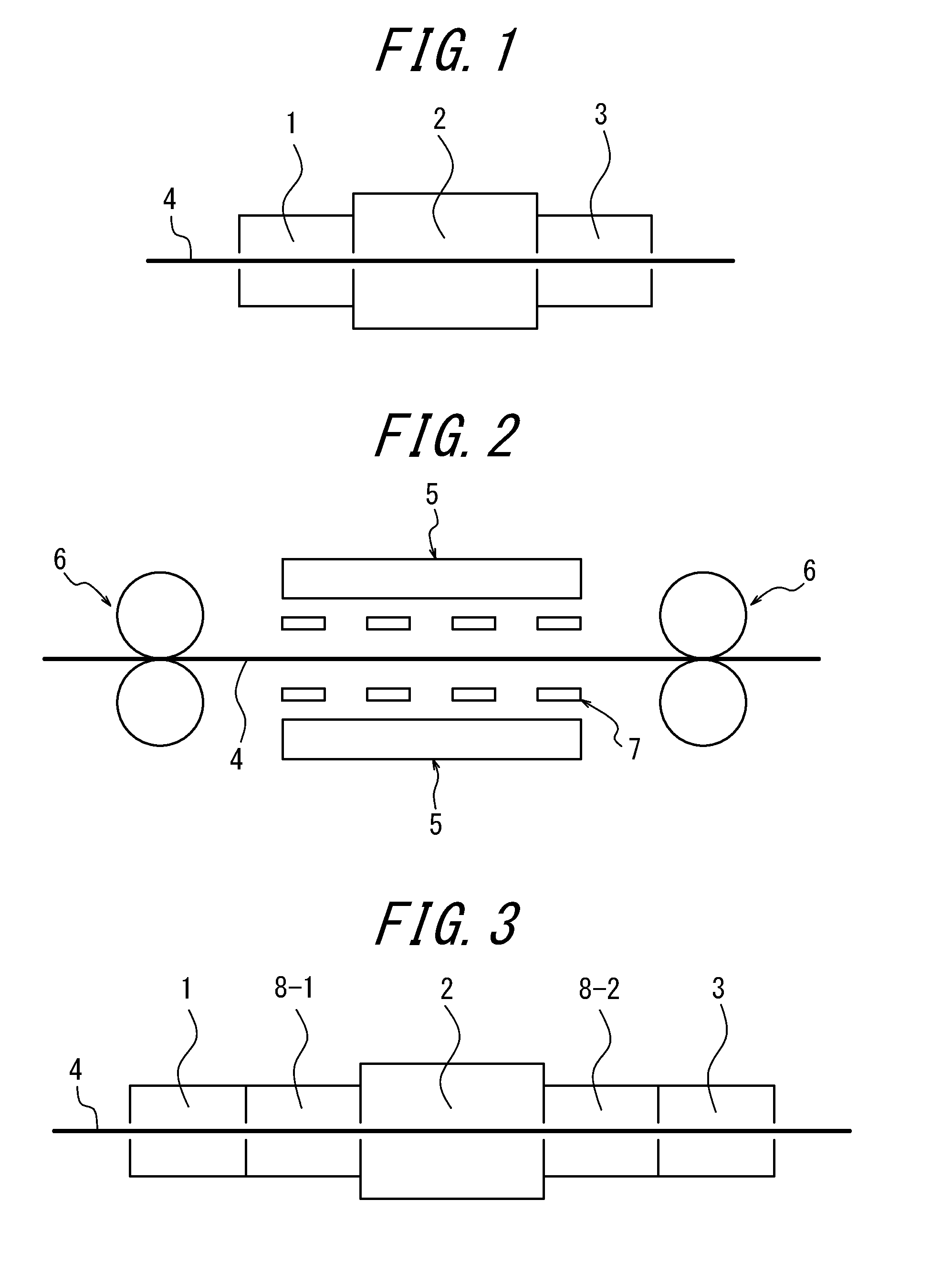
[0041] FIG. 1 schematically shows a preferable example of the nitriding apparatus of the disclosure.
[0042] FIG. 2 shows a preferable example of a plasma nitriding device according to the disclosure.
[0043] FIG. 3 schematically shows another example of the nitriding apparatus of the disclosure.
DETAILED DESCRIPTION
[0044] Our methods and components will be described in detail below.
[0045] FIG. 1 schematically shows a preferable example of the nitriding apparatus of the disclosure. In the figure, a heating zone is labeled 1, a nitriding zone is labeled 2, and a cooling zone is labeled 3. Further, a strip (steel sheet) continuously passing inside the nitriding apparatus with a structure comprising the aforementioned components is labeled 4. The heating zone may be provided when required and is not always necessary.
[0046] In the disclosure, a strip 4 is subjected to plasma nitriding by glow discharge in the above nitriding zone 2.
[0047] FIG. 2 shows a preferable example of a plasma nitriding device according to the disclosure. In the figure, positive electrodes for glow discharge disposed opposite to the strip 4 are labeled 5, pinch rolls are labeled 6, and negative electrodes disposed near the strip 4 are labeled 7.
[0048] The inner part of the nitriding zone 2 is filled with nitrogen gas and hydrogen gas as nitrogen sources.
[0049] A voltage is applied between the positive electrodes 5 and the negative electrodes 7 to generate glow discharge, and by irradiating the strip 4 with the plasma generated during glow discharge generation, the surface of the strip 4 is subjected to nitriding.
[0050] As described above, in the disclosure, it is necessary for the plasma generated between the positive electrodes and the negative electrodes to pass through the negative electrodes and reach the strip. Therefore, the negative electrodes must be perforated or mesh-like.
[0051] When performing the above nitriding, the strip is preferably heated to a temperature of 400.degree. C. or higher.
[0052] Further, the inside of the nitriding zone is preferably kept under a reduced pressure.
[0053] Further, although the heating zone and the cooling zone have a lower degree of pressure reduction compared to the nitriding zone, it is preferable for them to be kept in a state with reduced pressure compared to atmospheric pressure, and by doing so, heat exchange due to convection tends to proceed, and heating and cooling efficiency can be improved.
[0054] The inside of the nitriding zone is preferably depressurized to around 0.5 torr to 10 torr which is a preferable glow discharge condition, and the heating zone and the cooling zone are preferably depressurized, with a lower degree of pressure reduction, to around 30 torr to 500 torr.
[0055] Next, FIG. 3 shows an upstream atmosphere adjusting zone 8-1 and a downstream atmosphere adjusting zone 8-2 with a nitriding zone 2 in between.
[0056] In this case, each of the upstream atmosphere adjusting zone 8-1 and the downstream atmosphere adjusting zone 8-2 is preferably divided into multiple air chambers where the degrees of pressure reduction are individually adjustable. In a preferable construction, the degrees of pressure reduction of the air chambers in the upstream atmosphere adjusting zone 8-1 are gradually increased toward the nitriding zone 2, while the degree of pressure reduction of the air chambers in the downstream atmosphere adjusting zone 8-2 are gradually decreased from the nitriding zone 2 toward the cooling zone 3.
[0057] As the seal between each zone and each air chamber, conventionally known airtight seals may be used, such as rolls, seal pads and the like.
[0058] In a preferable structure, the inside of the nitriding zone is divided into multiple zones in the width direction of the strip where nitriding can be performed individually inside each divided zone. By adopting such structure, it is possible to effectively eliminate non-uniformity in nitridation in the width direction of the strip, such as excessive nitriding of the edges due to edge effects.
[0059] The heating zone can be omitted if it is disposed in a continuous line for performing other necessary treatment and the strip is already heated, or if the heating by plasma irradiation at the time of plasma nitriding is sufficient.
[0060] Further, in a case where another treatment is performed after plasma nitriding with the strip at a heated state, the cooling zone may be disposed after the zone for such treatment.
[0061] Further, the nitriding apparatus disclosed herein may be an independent apparatus that continuously performs only nitriding, or be attached to a processing line for performing another treatment, and in the case of a continuous line, it may be attached to the optimal place considering conditions including efficiency.
[0062] In the disclosure, the strip which is the material to be treated is not particularly limited and, as long as it is a grain-oriented electrical steel strip, any conventionally known strip is applicable.
REFERENCE SIGNS LIST
[0063] 1 Heating Zone [0064] 2 Nitriding Zone [0065] 3 Cooling Zone [0066] 4 Strip (Steel Sheet) [0067] 5 Positive Electrode [0068] 6 Pinch Roll [0069] 7 Negative Electrode [0070] 8-1 Upstream Atmosphere Adjusting Zone [0071] 8-2 Downstream Atmosphere Adjusting Zone
* * * * *
D00000
D00001
XML
uspto.report is an independent third-party trademark research tool that is not affiliated, endorsed, or sponsored by the United States Patent and Trademark Office (USPTO) or any other governmental organization. The information provided by uspto.report is based on publicly available data at the time of writing and is intended for informational purposes only.
While we strive to provide accurate and up-to-date information, we do not guarantee the accuracy, completeness, reliability, or suitability of the information displayed on this site. The use of this site is at your own risk. Any reliance you place on such information is therefore strictly at your own risk.
All official trademark data, including owner information, should be verified by visiting the official USPTO website at www.uspto.gov. This site is not intended to replace professional legal advice and should not be used as a substitute for consulting with a legal professional who is knowledgeable about trademark law.