Apparatus And Methods For Engaging Tissue
Kokish; Arkady
U.S. patent application number 16/223765 was filed with the patent office on 2019-04-25 for apparatus and methods for engaging tissue. The applicant listed for this patent is Abbott Laboratories. Invention is credited to Arkady Kokish.
| Application Number | 20190117205 16/223765 |
| Document ID | / |
| Family ID | 41316871 |
| Filed Date | 2019-04-25 |


View All Diagrams
| United States Patent Application | 20190117205 |
| Kind Code | A1 |
| Kokish; Arkady | April 25, 2019 |
APPARATUS AND METHODS FOR ENGAGING TISSUE
Abstract
A system includes a tissue engaging device and a delivery device that cooperates with the tissue engaging device. The tissue engaging device includes a distal tissue penetrating tip and two locking portions at a proximal end. The two locking portions move radially outwardly to transition the tissue engaging device from an unlocked configuration to a locked configuration. The delivery device includes a first elongate member being configured to selective extend distally past the two locking portions. A member, with a protruding portion disposed at a distal end of the delivery device, extends radially inwardly and is configured to selectively cooperate with the proximal end of the tissue engaging device to prevent rotational movement of the tissue engaging device relative to the delivery device.
| Inventors: | Kokish; Arkady; (Los Gatos, CA) | ||||||||||
| Applicant: |
|
||||||||||
|---|---|---|---|---|---|---|---|---|---|---|---|
| Family ID: | 41316871 | ||||||||||
| Appl. No.: | 16/223765 | ||||||||||
| Filed: | December 18, 2018 |
Related U.S. Patent Documents
| Application Number | Filing Date | Patent Number | ||
|---|---|---|---|---|
| 15069230 | Mar 14, 2016 | |||
| 16223765 | ||||
| 12122603 | May 16, 2008 | 9282965 | ||
| 15069230 | ||||
| Current U.S. Class: | 1/1 |
| Current CPC Class: | A61B 17/00234 20130101; A61B 2017/00663 20130101; A61B 17/10 20130101; A61B 2017/00584 20130101; A61B 2017/00672 20130101; A61B 17/3423 20130101; A61B 17/083 20130101; A61B 17/0057 20130101; A61B 17/08 20130101; A61B 2017/00004 20130101 |
| International Class: | A61B 17/00 20060101 A61B017/00; A61B 17/10 20060101 A61B017/10; A61B 17/34 20060101 A61B017/34; A61B 17/08 20060101 A61B017/08 |
Claims
1. A system comprising: a tissue engaging device comprising: a distal tissue penetrating tip; and two locking portions at a proximal end, wherein the two locking portions move radially outwardly to transition the tissue engaging device from an unlocked configuration to a locked configuration; a delivery device cooperating with the tissue engaging device, the delivery device comprising: a first elongate member extending from a second elongate member, the first elongate member being disposed within an opening of the tissue engaging device that extends from the distal end towards the proximal end, the first elongate member being configured to selectively extend distally past the two locking portions; and a member with a protruding portion disposed at a distal end of the delivery device and extending radially inwardly, the protruding portion selectively cooperating with the proximal end of the tissue engaging device, the cooperation of the protruding portion and the tissue engaging device preventing rotational movement of the tissue engaging device relative to the delivery device.
2. The system of claim 1, wherein the two locking portions cooperate with two other locking portions to lock the tissue engaging device in the locked configuration.
3. The system of claim 1, further comprising a locator extendable through the elongate member.
4. The system of claim 1, wherein the tissue engaging device comprises a first member and a second member that pivotally cooperate.
5. The system of claim 1, further comprising a concave portion formed in the second elongate member, the concave portion receiving a portion of the tissue engaging device.
6. The system of claim 1, wherein the protruding member selective cooperates with an opening formed in the proximal end of the tissue engaging device.
7. The system of claim 1, wherein the tissue engaging device comprise a bioabsorbable material, a biodegradable material, or bioerodible material.
8. A system comprising: a tissue engaging device comprising: two distal tissue penetrating tips; and two locking portions at a proximal end, wherein the two locking portions move radially outwardly to transition the tissue engaging device from an unlocked configuration to a locked configuration, the two locking portions are disposed on opposite sides of a longitudinal axis of the tissue engaging device; a delivery device cooperating with the tissue engaging device, the delivery device comprising: a first elongate member extending from a second elongate member, the first elongate member being disposed within an opening of the tissue engaging device that extends from the distal end towards the proximal end, the first elongate member being configured to extend distally past the two locking portions with the two distal tissue penetrating tips being in a tissue-capture open configuration; and a member with a protruding portion disposed at a distal end of the delivery device and extending radially inwardly, the protruding portion selectively cooperating with the proximal end of the tissue engaging device, the cooperation of the protruding portion and the tissue engaging device preventing rotational movement of the tissue engaging device relative to the delivery device.
9. The system of claim 8, wherein the two locking portions cooperate with two other locking portions to lock the tissue engaging device in the locked configuration.
10. The system of claim 8, wherein the tissue engaging device comprises a first member and a second member.
11. The system of claim 10, wherein a distal end of each the first member and the second member is formed with one of the two distal tissue penetrating tips.
12. The system of claim 8, further comprising a concave portion formed in the second elongate member, the concave portion receiving a portion of the tissue engaging device.
13. The system of claim 8, wherein the protruding portion selectively cooperates with an opening formed in the tissue engaging device, the opening extending through the tissue engaging device in a proximal to distal direction.
14. The system of claim 8, wherein the tissue engaging device comprise a bioabsorbable material, a biodegradable material, or bioerodible material.
15. A method for capturing tissue, the method comprising: positioning a tissue engaging device to capture tissue, the tissue engaging device comprising: a distal tissue penetrating tip; and two locking portions at a proximal end, wherein the two locking portions move radially outwardly to transition the tissue engaging device from an unlocked configuration to a locked configuration; capturing tissue with the tissue engaging device and deploying the tissue engaging device from a delivery device, the delivery device comprising: a first elongate member extending from a second elongate member, the first elongate member being disposed within an opening of the tissue engaging device that extends from the distal end towards the proximal end, the first elongate member being configured to selective extends distally past the two locking portions; and a member with a protruding portion disposed at a distal end of the delivery device and extending radially inwardly, the protruding portion selectively cooperating with the proximal end of the tissue engaging device, the cooperation of the protruding portion and the tissue engaging device preventing rotational movement of the tissue engaging device relative to the delivery device; and removing the delivery device.
16. The method of claim 15, further comprising advancing a locator through the first elongate member.
17. The method of claim 15, further comprising moving a distal end of the second elongate member relative to the proximal end of the tissue engaging device to deploy the tissue engaging device.
18. The method of claim 17, wherein the distal end comprises a concave portion.
19. The method of claim 15, wherein capturing tissue with the tissue engaging device comprises pivoting the distal tissue penetrating tip about an intermediate portion of the tissue engaging device.
20. The method of claim 15, wherein removing the delivery device comprises withdrawing the protruding portion from engaging with the tissue engaging device.
Description
CROSS-REFERENCE TO RELATED APPLICATIONS
[0001] This application is a continuation of U.S. patent application Ser. No. 15/069,230, filed Mar. 14, 2016, now U.S. Pat. No. ______, entitled "Apparatus and Methods for Engaging Tissue", which is a continuation of U.S. patent application Ser. No. 12/122,603, filed May 16, 2008, now U.S. Pat. No. 9,282,965, entitled "Apparatus and Methods for Engaging Tissue", the entireties of which are incorporated herein by reference.
FIELD OF THE INVENTION
[0002] The present invention relates generally to medical devices, and more particularly to apparatus and methods for engaging tissue.
BACKGROUND OF THE INVENTION
[0003] Catheterization and interventional procedures, such as angioplasty or stenting, generally are performed by inserting a hollow needle through a patient's skin and tissue into the vascular system. A guidewire may be advanced through the needle and into the patient's blood vessel accessed by the needle. The needle is then removed, enabling an introducer sheath to be advanced over the guidewire into the vessel, e.g., in conjunction with or subsequent to a dilator.
[0004] A catheter or other device may then be advanced through a lumen of the introducer sheath and over the guidewire into a position for performing a medical procedure. Thus, the introducer sheath may facilitate introducing various devices into the vessel, while minimizing trauma to the vessel wall and/or minimizing blood loss during a procedure.
[0005] Upon completing the procedure, the devices and introducer sheath are removed, leaving a puncture site in the vessel wall. Traditionally, external pressure had often been applied to the puncture site until clotting and wound sealing would occur; however, the patient must remain bedridden for a substantial period of time after clotting to ensure closure of the wound. This procedure, however, may be time consuming and expensive, requiring as much as an hour of a physician's or nurse's time. It is also uncomfortable for the patient and requires that the patient remain immobilized in the operating room, catheter lab, or holding area. In addition, a risk of hematoma exists from bleeding before hemostasis occurs.
[0006] Various apparatus have been suggested for percutaneously sealing a vascular puncture by occluding the puncture site. For example, U.S. Pat. Nos. 5,192,302 and 5,222,974, issued to Kensey et al., describe the use of a biodegradable plug that may be delivered through an introducer sheath into a puncture site. Another technique has been suggested that involves percutaneously suturing the puncture site, such as that disclosed in U.S. Pat. No. 5,304,184, issued to Hathaway et al.
[0007] To facilitate positioning devices that are percutaneously inserted into a blood vessel, "bleed back" indicators have been suggested. For instance, U.S. Pat. No. 5,676,689, issued to Kensey et al., discloses a bleed back lumen intended to facilitate positioning of a biodegradable plug within a puncture site. This device, however, requires that an anchor of the plug be positioned within the vessel, and therefore, may increase the risk of over-advancement of the plug itself into the vessel.
[0008] Alternatively, U.S. Pat. No. 5,674,231, issued to Green et al., discloses a deployable loop that may be advanced through a sheath into a vessel. The loop is intended to resiliently expand in order to engage the inner wall of the vessel, thereby facilitating holding the sheath in a desired location with respect to the vessel.
[0009] Accordingly, additional apparatus and methods for engaging tissue would be useful.
BRIEF SUMMARY
[0010] An embodiment of an engaging element for engaging tissue is described. The engaging element includes a first member having at least one tissue engaging portion. The engaging element includes a second member having at least one tissue engaging portion and being pivotally connected to the first member. The engaging element includes a locking mechanism that is operatively associated with the first and second member. The locking mechanism is configured to inhibit the relative motion of the first and second member.
[0011] An embodiment of an engaging system for engaging tissue is described. The engaging system includes an engaging element for engaging tissue. The engaging element includes a first member having at least one tissue engaging portion. The engaging element also includes a second member including at least one tissue engaging portion. The second member is pivotally connected to the first member. The engaging element further includes a locking mechanism operatively associated with the first and second member. The locking mechanism is configured to inhibit the relative motion of the first and second member. The engaging system also includes an engaging element delivery device. The engaging element delivery device includes a transitioning member. The transitioning member is configured to transition the engaging element from an open configuration toward a closed configuration.
[0012] A method for engaging tissue is described. The method includes positioning an engaging element relative to an engaging element delivery device. The engaging element includes a first member having at least one tissue engaging portion. The engaging element also includes a second member having at least one tissue engaging portion. The second member is pivotally connected to the first member. The engaging element further includes a locking mechanism operatively associated with the first and second member. The locking mechanism is configured to inhibit the relative motion of the first and second member. The engaging element delivery device includes a retaining member. The retaining member includes a retaining mechanism and a transitioning member. The engaging element is positioned relative to a portion of tissue. A portion of the tissue is engaged with at least one tissue engaging portion. The engaging element is transitioned from an open configuration toward a closed configuration using the transitioning member. A locking mechanism is activated using the transitioning member to inhibit the relative motion of the first member and the second member.
[0013] In some embodiments of an engaging member, the first and second member include a proximal end. In further embodiments of an engaging member, the proximal ends of the first member and second member are separated by a first transitioning dimension in an open configuration and a second transitioning dimension in a closed configuration.
[0014] The first transitioning dimension, in some embodiments of an engaging member, is larger than said second transitioning dimension. In other embodiments of an engaging member, the first transitioning dimension is smaller than said second transitioning dimension. In further embodiments of an engaging member, the locking mechanism includes a first locking portion and a second locking portion, such that movement of the at least one tissue engaging portions of the first and second members is inhibited by the operative association between the first and second locking portions.
[0015] In some embodiments of an engaging member, the first locking portion includes at least one tooth associated with the first member and the second locking portion includes a locking member associated with the second member. In other embodiments of an engaging member, the locking member is biased toward the at least one tooth.
[0016] The locking member and the at least one tooth, in some embodiments of an engaging member, inhibit the at least one tissue engaging portions of the first and second members from moving toward the open configuration. In further embodiments of an engaging member, the first locking portion includes a latch associated with the first member and the second locking portion includes a latching portion associated with the second member. In still further embodiments of an engaging member, the latch and the latching portion inhibit the at least one tissue engaging portion of the first and second members from moving toward the open configuration.
[0017] In some embodiments of an engaging member, at least one tissue engaging portion of the first member and the at least one tissue engaging portion of the second member are separated by a first distal dimension in an open configuration and are separated by a second distal dimension in a closed configuration. The first distal dimension is larger than the second distal dimension, in some embodiments of an engaging member.
[0018] The engaging element, in some embodiments, includes a pivoting mechanism operatively associated with the first and the second members. In further embodiments of an engaging member, the pivoting mechanism includes a pivoting opening associated with one of the first member and the second member and a pivoting member associated with the other of the first member and the second member.
[0019] In some embodiments of an engaging member, the engaging element further comprises a retaining portion configured to be operatively associated with a retaining mechanism. In further embodiments of an engaging member, the engaging element includes bioabsorbable, biodegradable, and/or bioerodible material. In still further embodiments, the engaging element includes collagen, polycaprolactone (PCL), poly-D,L-lactic acid, Poly-L-lactic acid, poly (lactide-co-glycolide), poly(hydroxybutyrate), polyanhydrides, and/or poly(glycolic acid).
[0020] The engaging element, in some embodiments of an engaging system, includes a pivoting mechanism operatively associated with said first and said second member. Further embodiments of an engaging system include a retaining member that has a retaining mechanism configured to selectably inhibit the relative motion of said engaging element and said retaining member.
[0021] In some embodiments of an engaging system, a pivoting mechanism includes a pivoting opening associated with one of the first and second member and a pivoting member associated with the other of the first and second member. In further embodiments of an engaging system, the retaining mechanism is operatively associated with the pivoting opening to selectably inhibit the relative motion of the engaging element and the retaining member. In still further embodiments of an engaging system, the retaining mechanism includes a retaining detent that engages the pivoting opening to selectably inhibit the relative motion of the engaging element and the retaining member.
[0022] The retaining member and the transitioning member, in some embodiments of an engaging system, are axially aligned. In further embodiments of an engagement system, the retaining member is configured to slidably receive the transitioning member.
[0023] In some embodiments of an engaging system, the first and second member of the engaging element include a transitioning portion. The transitioning member, in further embodiments, includes a transitioning surface that is shaped to engage with the transitioning portion of at least one of the first and second member of the engaging element. In some embodiments, the transitioning surface has a convex shape. In other embodiments, the transitioning surface has a concave shape.
[0024] Some embodiments of a method for engaging tissue include selectably retaining the engaging element using a retaining mechanism to inhibit the relative motion of the engaging element and the retaining member. Further embodiments of a method for engaging tissue include disengaging the locking mechanism.
[0025] Other aspects and features of the present invention will become apparent from consideration of the following description in conjunction with the accompanying drawings.
BRIEF DESCRIPTION OF THE DRAWINGS
[0026] In order to describe the manner in which the above-recited and other advantages and features of the invention can be obtained, a more particular description of the invention will be rendered by reference to specific embodiments thereof which are illustrated in the appended drawings. Understanding that these drawings depict only typical embodiments of the invention and are not therefore to be considered to be limiting of its scope, the invention will be described and explained with additional specificity and detail through the use of the accompanying drawings.
[0027] FIG. 1A is a perspective partial cutaway view of an embodiment of a system for engaging tissue with an engaging element in an open configuration, according to an embodiment of the present invention.
[0028] FIG. 1B is a perspective partial cutaway view of the embodiment of a system for engaging tissue of FIG. 1A with an engaging element in a closed configuration, according to the present invention.
[0029] FIG. 1C is a top cutaway view of the embodiment of the system for engaging tissue of FIG. 1A, according to the present invention.
[0030] FIG. 2A is a perspective view of another embodiment of an engaging element in an open configuration, according to the present invention.
[0031] FIG. 2B is a perspective view of the embodiment of the engaging element of FIG. 2A in a closed configuration, according to the present invention.
[0032] FIG. 2C is a perspective view of an embodiment of a system for engaging tissue with the embodiment of the engaging element of FIG. 2A in an open configuration, according to the present invention.
[0033] FIG. 2D is a perspective partial cutaway view of the embodiment of a system for engaging tissue of FIG. 2C with the embodiment of the engaging element of FIG. 2A in a closed configuration, according to the present invention.
[0034] FIG. 2E is a right cutaway view of the embodiment of the system for engaging tissue of FIG. 2C with the embodiment of the engaging element of FIG. 2A in an open configuration, according to the present invention.
[0035] FIG. 2F is a right cutaway view of the embodiment of the system for engaging tissue of FIG. 2C with the embodiment of the engaging element of FIG. 2A in a closed configuration, according to the present invention.
[0036] FIGS. 3A-3K illustrate various steps in the deployment of an embodiment of an engaging element to engage tissue according to one example.
[0037] It should be noted that the figures are not drawn to scale and that elements of similar structures or functions are generally represented by like-reference numerals for illustrative purposes throughout the figures. It also should be noted that the figures are only intended to facilitate the description of embodiments of the present invention.
DETAILED DESCRIPTION
[0038] Embodiments described herein extend to methods, systems, and apparatus for engaging tissue. Some embodiments may be used to close and/or seal openings in a blood vessel or other body lumen formed during a diagnostic, therapeutic, and/or other procedure. The engaging elements of the present invention may be configured to be delivered through tissue and into an opening formed in and/or adjacent to a wall of a blood vessel or other body lumen. The engaging elements provided herein may reliably engage.
[0039] Moreover, the engaging elements may be made of any suitable material, including a bioabsorbable material, such as collagen. Other biodegradable materials may include polycaprolactone (PCL), poly-D,L-lactic acid, Poly-L-lactic acid, poly (lactide-co-glycolide), poly(hydroxybutyrate), polyanhydrides, poly(glycolic acid, and/or other biodegradable materials.
[0040] Referring generally to FIGS. 1A-1C, the system 100 may include an engaging element 110 and an engaging element delivery device 160. The engaging element 110 may include a first member 112 and a second member 114. The first member 112 and the second member 114 may include tissue engaging portions 116 (three tissue engaging portions 116 on each of the first member 112 and the second member 114, in the present embodiment). The tissue engaging portions 116 may include a sharpened tip, as shown, and/or may include other tips, such as barbed tips. The tissue engaging portions 116 may be configured to engage tissue.
[0041] The engaging element delivery device 160 may include a retaining member 164, a transitioning member 168, a carrier member 172, a locator 176, and/or other components. The transitioning member 168 may include a lumen. The lumen may receive the carrier member 172, the locator 176, and/or other components. The carrier member 172 may be configured to receive a locator 176 and/or other components.
[0042] The engaging element 110, locator 176, carrier member 172, transitioning member 168, and/or retaining member 164 may be axially aligned. The carrier member 172 and/or locator 176 may be configured to fit within a channel of the engaging element 110 in the open configuration.
[0043] The first member 112 and second member 114 may be pivotally connected. The first member 112 and second member 114 may be pivotally connected by a pivoting mechanism 120. The pivoting mechanism 120 may include a pivoting opening 122 and a pivoting member 124. The pivoting member 124 may be located on the first member 112 and the pivoting opening 122 may be located on the second member 114. Alternatively, the pivoting member 124 and pivoting opening 122 may be located on either the first member 112 or the second member 114. Other pivoting mechanisms 120 may also be used. The pivoting member 124 of the present embodiment may include a detent configured to engage the pivoting opening 122.
[0044] The engaging element 110 may include a transitioning portion 130 with a first transitioning dimension 132a, in the open configuration shown in FIG. 1A, and a second transitioning dimension 132b in the closed configuration shown in FIG. 1B. Transitioning dimensions 132a, 132b may indicate distances between the first member 112 and the second member 114 in various configurations. The first transitioning dimension 132a may be smaller than the second transitioning dimension 132b.
[0045] The engaging element 110 may include a first distal dimension 134a in the open configuration and a second distal dimension 134b in the closed configuration. Distal dimensions 134a, 134b may indicate distances between the first member 112 and the second member 114 in various configurations. The first distal dimension 134a may be larger than the second transitioning dimension 132b.
[0046] The transitioning portion 130 may be configured to receive a distal end of the transitioning member 168. The transitioning member 168 may include a transitioning surface 170 located near the distal end. The transitioning member 168 may be elongate and/or convex. The transitioning surface 170 may be operatively associated with the transitioning portion 130 of the engaging element 110 to transition the engaging element 110 from the open configuration toward the closed configuration.
[0047] Referring to FIGS. 1A and 1B, transitioning the engaging element 110 from the open configuration toward the closed configuration may include expanding the first transitioning dimension 132a toward the second transitioning dimension 132b. As the transitioning surface 170 of the transitioning member 168 engages the transitioning portion 130 of the engaging element 110, the proximal ends of the first member 112 and second member 114 may expand away from each other. As the proximal ends expand away from each other (from the open configuration), the tissue engaging portions 116 of the first member 112 and the second member 114 may move toward each other (toward the closed configuration).
[0048] The engaging element 110 may include a locking mechanism 140 that may be configured to generally inhibit movement from the closed configuration towards the open configuration. For example, as the proximal ends expand away from each other, the locking mechanism 140 may inhibit movement back toward the open configuration.
[0049] The locking mechanism 140 may include a first locking portion 142 and a second locking portion 144. The first locking portion 142 and the second locking portion 144 may be operatively associated. The first locking portion 142 and/or the second locking portion 144 may be located near the proximal ends of the first member 112 and/or the second member 114, respectively. The first locking portion 142 may include at least one tooth. The at least one tooth may be configured to receive the second locking portion 144 which may include a locking member such as a follower. The locking member may be biased toward the at least one tooth. The use of multiple teeth may incrementally inhibit movement toward the open configuration.
[0050] The pivoting opening 122 may include a retaining portion. The pivoting opening 122 may be configured to receive at least a portion of a retaining mechanism 166 on the retaining member 164 and the pivoting member 124 of the engaging element 110. The pivoting opening 122 and retaining mechanism 166 may be operatively associated to limit movement of the engaging element 110 in at least one direction. For instance, the pivoting opening 122 and retaining mechanism 166 may limit motion of the engaging element 110 both longitudinally (i.e. through the retaining member 164) and radially (i.e. about an axis within the retaining member 164). The engaging element 110 may be inserted through the retaining member 164 until the retaining mechanism 166 and the pivoting opening 122 are retained. Alternatively, the retaining portion may be located on the retaining member 164 while the retaining mechanism 166 is located on the engaging element 110. Other retaining portion and/or retaining mechanism combinations, such as a detent and retaining groove combination, may be used.
[0051] In order to align the pivoting opening 122 of the engaging element 110 with the retaining mechanism 166 of the retaining member 164, the engaging element 110 may include an aligning portion 150, as shown in FIGS. 1A and 1B, which may be operatively associated with an aligning mechanism 167 of the retaining member 164. The aligning portion 150 of the engaging element 110 may include a ridge configured to be inserted into the aligning mechanism 167 (i.e. a corresponding slot or groove) of the retaining member 164. In another embodiment, the aligning portion 150 of the engaging element 110 may be a slot or groove configured to receive the aligning mechanism 167, i.e. ridge, tab, etc., of the retaining member 164. In further embodiments, the aligning portion 150 and/or the aligning mechanism 167 may take other forms to align the engaging element 110 with the retaining member 164 and/or transitioning member 168.
[0052] Referring to FIGS. 2A-2F, the system 200 and engaging element 210 of this embodiment may be at least partially functionally similar to that of the system 100 and engaging element 210 previously described above and shown in FIG. 1 in most respects, wherein certain features will not be described in relation to this embodiment wherein those components may function in the manner as described above and are hereby incorporated into this alternative embodiment described below. Like structures and/or components are given like reference numerals.
[0053] The engaging element 210 may include a first member 212 and a second member 214. The first member 212 and the second member 214 may be configured to engage tissue. The tissue engaging portions 216 may include tissue engaging portions 216 that may include a sharpened tip, barb, and/or other tip.
[0054] The first member 212 and second member 214 may be pivotally connected by a pivoting mechanism 220. The pivoting mechanism 220 may include a pivoting opening 222 and a pivoting member 224. The pivoting opening 222 may be located on the first member 212 and the pivoting member 224 may be located on the second member 214.
[0055] The engaging element 210 may include a transitioning portion 230 with a first transitioning dimension 232a, in the open configuration shown in FIG. 2A, and a second transitioning dimension 232b in the closed configuration shown in FIG. 2B. The first transitioning dimension 232a may be larger than the second transitioning dimension 232b.
[0056] The engaging element 210 may include a first distal dimension 234a in the open configuration and a second distal dimension 234b in the closed configuration. The first distal dimension 134a may be larger than the second transitioning dimension 232b.
[0057] Referring to the system 200 shown in FIGS. 2C-2D, the engaging element delivery device 260 may include a transitioning member 268, a retaining member 264, a carrier member 272, a locator 276, and/or other components. The transitioning portion 230 of the engaging element 210 may be configured to receive a distal end of the transitioning member 268. The transitioning member 268 may include a transitioning surface 270 located near the distal end that may be concave. The transitioning surface 270 may be operatively associated with the transitioning portion 230 of the engaging element 210 to transition the engaging element 210 from the open configuration toward the closed configuration.
[0058] Referring to FIGS. 2C-2F, transitioning the engaging element 210 from the open configuration toward the closed configuration may include moving the first transitioning dimension 232a toward the second transitioning dimension 232b. As the transitioning surface 270 of the transitioning member 268 engages the transitioning portion 230 of the engaging element 210, the proximal ends of the first member 212 and second member 214 may move toward each other. As the proximal ends move toward each other (from the open configuration), the tissue engaging portions 216 of the first member 212 and the second member 214 may also move toward each other (toward the closed configuration).
[0059] The engaging element 210 may include a locking mechanism 240 that may be configured to generally inhibit movement from the closed configuration towards the open configuration. For example, as the proximal ends move toward each other the locking mechanism 240 may inhibit movement toward the open configuration.
[0060] The locking mechanism 240 may include a first locking portion 242 and a second locking portion 244. The first locking portion 242 and the second locking portion 244 may be operatively associated. The first locking portion 242 and/or the second locking portion 244 may be located near the proximal ends of the first member 212 and/or the second member 214, respectively. The first locking portion 242 may include a latch member. The latch member may be configured to engage the second locking portion 244 which may include a latching portion. The latch member may be biased to engage the latching portion. Although the latch member and latching portion may be located on the first member 212 and the second member 214, respectively, other locations may also be used. Furthermore, although a locking member and tooth combination and a latch member and latching portion combination have been described, other locking mechanisms may be used. For instance, a set of interlocking teeth may be disposed on the first member 212 and the second member 214 similar to the locking mechanism used for locking forceps.
[0061] The pivoting opening 222 may include a retaining portion that may be configured to receive a retaining mechanism 266 on the retaining member 264. The pivoting opening 222 and retaining mechanism 266 may be operatively associated to limit movement of the engaging element 210 in at least one direction.
[0062] The engaging element 210 of the present embodiment may include two types of aligning portions 250a, 250b. The aligning portions 250a near the proximal end of the engaging element 210 may be grooves configured to receive an aligning mechanism 271 (i.e. a ridge) on the transitioning member 268. The aligning portions 250b near the tissue engaging portions 216 may be ridges configured to be inserted into a first aligning mechanism 267, i.e. a corresponding slot or groove, of the retaining member 264. Other alignment portions 250a, 250b, alignment mechanisms 267, 271, and/or configurations of the same (i.e. alignment portions and/or alignment mechanisms on the engaging element 210, retaining member 264, transitioning member 268, and/or other components) may be used to orient the engaging element 210 relative to the engaging element delivery device 260 such that the retaining member 264 may retain the engaging element 210.
[0063] The transitioning member 268 may include a lumen that may receive a carrier member 272, a locator 276, and/or other components. The carrier member 272 may be configured to receive a locator 276 and/or other components.
[0064] The transitioning member 268 may abut the transitioning portion 230 of the engaging element 210. The transitioning member 268 may include a transitioning surface 270 that is concave. As the transitioning member 268 is advanced through the retaining member 264, the transitioning member 268 may transition the engaging member 210 toward a closed configuration. The concave transitioning surface 270 may generally cause the proximal ends of the first member 212 and the second member 214 to move toward each other. As the proximal ends of the first member 212 and the second member 214 move toward each other, the tissue engaging portions 216 on the first member 212 and the second member 214 may move toward each other.
[0065] FIGS. 3A-3K illustrate various steps in the deployment of an embodiment of an engaging element 310 to close a puncture according to one example. The systems 100, 200 and engaging elements 110, 210 discussed above in connection with FIGS. 1A-1C and 2A-2F will now be discussed in the context of a patient and with respect to a blood vessel 390. The systems 100, 200 and engaging elements 110, 210 may also be used with body lumens other than blood vessels.
[0066] The system 300 and engaging element 310 of this embodiment may be at least partially functionally similar to that of the systems 100, 200 and engaging elements 110, 210 previously described above and shown in FIGS. 1 and 2 in most respects, wherein certain features will not be described in relation to this embodiment wherein those components may function in the manner as described above and are hereby incorporated into this alternative embodiment described below. Like structures and/or components are given like reference numerals.
[0067] The blood vessel 390 has a vessel wall 392 with an outer portion 392a and an inner portion 392b. The engaging element delivery device 360 may then be used to apply the engaging element 310. In particular, a sheath 380 may be inserted or otherwise positioned through skin 394 and tissue 396 and within the blood vessel 390 or other body lumen via an opening 398. The sheath 380 can include a substantially flexible or semi-rigid tubular member. Also, the sheath 380 can have a proximal end region 382a and a distal end region 382b. The sheath 380 may further have a predetermined length and a predetermined cross-section, both of which can be of any suitable dimension. The sheath 380 also can form a lumen 384 that extends along a longitudinal axis of the sheath 380 and substantially between the proximal and distal end regions 382a, 382b. The lumen 384 can have any suitable internal cross-section and is suitable for receiving one or more devices (not shown), such as a guidewire 388, a catheter, and/or other devices.
[0068] The sheath 380 may be advanced over a guidewire 388 and/or other rail that may have been positioned through the opening 398 and into the blood vessel 390 using conventional procedures. The blood vessel 390 can be a peripheral blood vessel, such as a femoral or carotid artery, although other body lumens may be accessed using the sheath 380. The opening 398, and consequently the sheath 380, may be oriented with respect to the blood vessel 390 such as to facilitate the introduction of devices through the lumen 384 of the sheath 380 and into the blood vessel 390 with minimal risk of damage to the blood vessel 390. One or more devices (not shown), such as a catheter, or the like, may be inserted through the sheath 380 and advanced to a preselected location within the patient's body. For example, the devices may be used to perform a therapeutic and/or diagnostic procedure, such as angioplasty, atherectomy, stent implantation, and the like, within the patient's vasculature.
[0069] After the procedure is completed, the devices may be removed from the sheath 380. The engaging element delivery device 360 may be prepared to be received by the lumen 384 of the sheath 380 as shown in FIG. 3B. Alternatively, the sheath 380 may be removed and then the engaging element delivery device 360 may be positioned near the opening 398. The engaging element delivery device 360 may include a retaining member 364, a transitioning member 368, a carrier member 372, a locator 376, and/or other components. The carrier member 372 may provide support for the engaging element 310. The locator 376 may be inserted through a channel in the carrier member 372.
[0070] The locator 376 may include a tubular body 378 having a distal end region 379. Being in the unexpanded state, the distal end region 379 of the tubular body 378 of the locator 376 can be slidably received by the lumen 384 and atraumatically advanced distally into the blood vessel 390 as illustrated in FIGS. 3B-3C. Advancing the distal end region 379 into the lumen 384 begins the location of the locator 376 relative to the blood vessel 390.
[0071] Once the distal end region 379 of the tubular body 378 extends into the blood vessel 390, the distal end region 379 may transition from the unexpanded state to the expanded state as shown in FIG. 3D. A triggering system (not shown) of the locator 376 may be used to transition from the unexpanded state to the expanded state. Locators other than the expandable locator may also be used. For instance, a bleedback lumen and/or other locator may be used to locate the body lumen. Alternatively, no locator may be used. Rather, the engaging element delivery device 360 may be advanced until a technician determines that the distal end is near the opening.
[0072] Turning to FIG. 3E, the engaging element delivery device 360 and the sheath 380 may be retracted proximally until the distal end region 379 is substantially adjacent to an inner surface 392b of the blood vessel wall 392. The distal end region 379 thereby may draw the blood vessel wall 392 taut and/or may maintain the proper position of the system 300 as the blood vessel 390 pulsates. Since the expanded cross-section of the distal end region 379 can be greater than or substantially equal to the cross-section of the opening 398 and/or the cross-section of the lumen 384, the distal end region 379 may remain in the blood vessel 390 and may engage the inner surface 392b of the blood vessel wall 392. The distal end region 379 may frictionally engage the inner surface 392b of the blood vessel wall 392, thereby securing the system 300 to the blood vessel 390. The sheath 380 can be retracted proximally such that the distal end region 382b of the sheath 380 may be substantially withdrawn from the blood vessel 390, as shown in FIG. 3E, permitting system 300 to access the blood vessel wall 392.
[0073] Once the distal end region 379 of the locator 376 contacts the inner surface 392b of the blood vessel wall 392, the engaging element delivery device 360 may be advanced distally and may be received within the lumen 384 of the sheath 380 as illustrated in FIG. 3F. The sheath 380 may radially expand and/or split in accordance with the predetermined pattern as the distal portion advances because the internal cross-section of the sheath 380 may be less than an outer portion of the retaining member 364.
[0074] Upon reaching the first predetermined position, the distal portion of the retaining member 364 can be disposed substantially adjacent to the outer surface 392a of the blood vessel wall 392 adjacent to the opening 398 such that the blood vessel wall 392 adjacent to the opening 398 may be disposed substantially between the expanded distal region 379 of the locator 376 and the distal portion of the retaining member 364. The engaging element 310 and retaining member 364 may be configured such that as the retaining member 364 approaches the distal end 379 of the locator 376, the tissue engaging portions 316 of the engaging member 310 may engage the outer portion 392a of the vessel wall 392.
[0075] As shown in FIG. 3G, which is rotated ninety degrees to illustrate the interaction of the first member 312 and second member 314 of the engaging element 310 during deployment, the transitioning member 368 may advance distally to cause the tissue engaging portions 316 of the engaging member 310 to move toward the closed configuration (i.e. from the first distal dimension to the second distal dimension). The convex transitioning surface 370 may cause the transitioning portion 330 of the engaging element 310 to transition toward the closed configuration (i.e. the proximal ends of the first member 312 and the second member 314 may move away from each other while the tissue engaging portions 316 move toward each other).
[0076] Alternatively, other transitioning members 368 and/or engaging elements 310 may be used. For example, the transitioning member 268 and engaging element 210 described in connection with FIGS. 2A-2D may be used, such that the concave transitioning surface 270 may cause the transitioning portion 230 of the engaging element 210 to transition toward the closed configuration (i.e. the proximal ends of the first member 212 and the second member 214 may move toward each other).
[0077] As the tissue engaging portions 316 move toward each other, the distal end 379 of the locator 376 may move toward the unexpanded configuration and/or begin to move proximally to allow the tissue engaging portions 316 to fully engage the vessel wall 392. Alternatively, the locator 376 may remain within the blood vessel 390 after the tissue engaging portions 316 have engaged the vessel wall 392 and/or may be later removed.
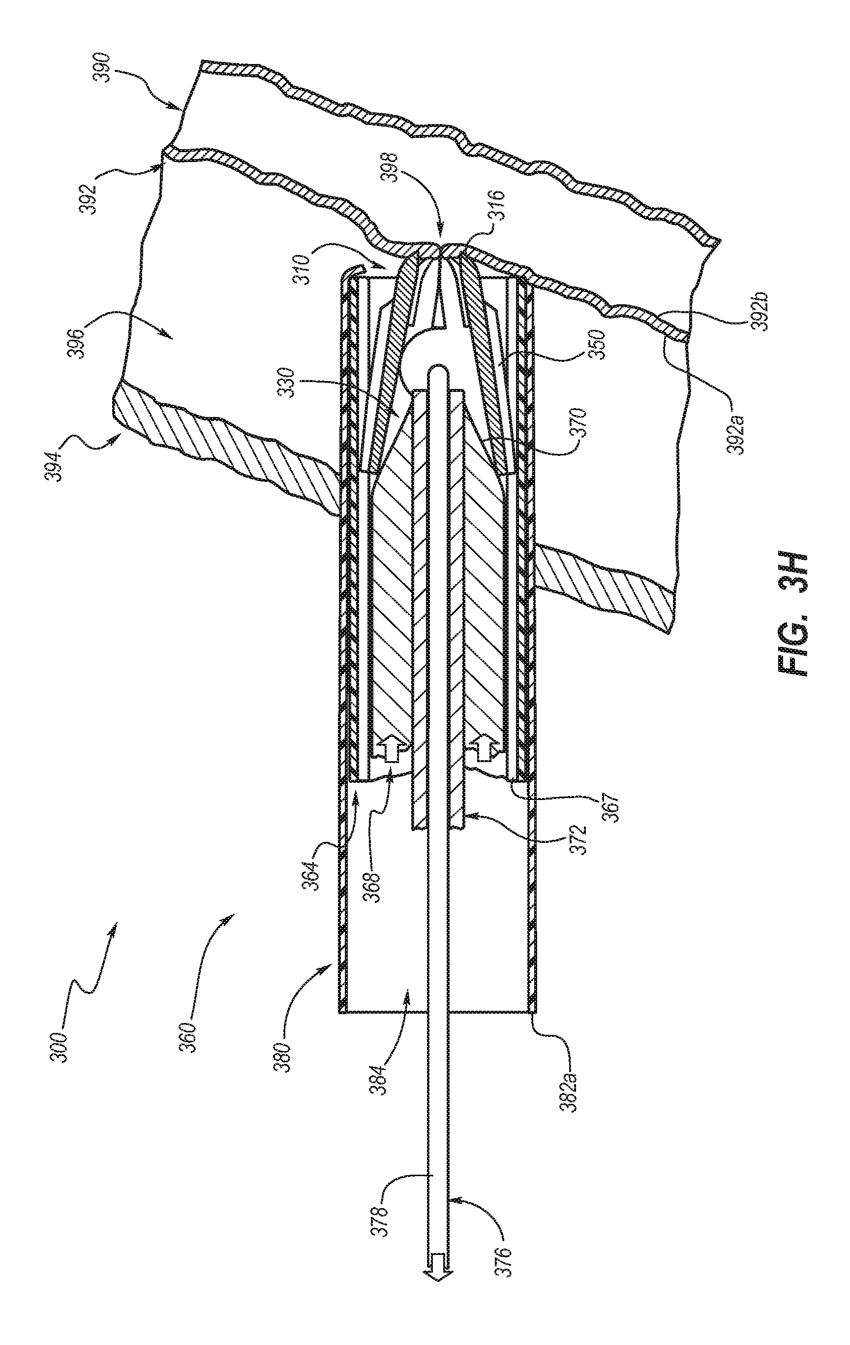
[0078] As shown in FIGS. 3H-3L, the engaging element 310 may be deployed. The engaging element 310 may engage the vessel wall 392 (as shown in FIG. 3F) in the open configuration. For instance, the tissue engaging portions 316 may frictionally, piercingly, and/or otherwise engage the vessel wall 392. As shown in FIG. 31, the transitioning member 368 may continue to apply distal pressure to the engaging element 310 as the retaining member 364 begins to advance distally. The retaining member 364 may begin to disengage from the engaging element 310. For example, the retaining mechanism 366 may begin to be removed from the pivoting opening 322 of the engaging element 310, as shown in FIG. 3I. The retaining member 364 may be fully removed while the transitioning member 368 maintains distal pressure on the engaging element 310, as shown in FIG. 3J. Then the remaining components of the system 300 may be removed through the skin 394, as shown in FIG. 3K. The engaging element 310 may remain between the outer surface 392a of the vessel wall 392 and the skin 394, i.e. within the tissue 396, while in the closed configuration. The opening 398 in the skin 394 may be closed with a bandage or other device.
[0079] Access to the body lumen may be restablished by unlocking the locking mechanism (140 shown in FIG. 1). For instance, a device (not shown) may be used to push the locking member and/or latch member out of engagement with the teeth and/or latching portion allowing the tissue engaging portions 316 to move away from each other toward the open configuration.
[0080] The invention is susceptible to various modifications and alternative means, and specific examples thereof have been shown by way of example in the drawings and are herein described in detail. It should be understood, however, that the invention is not to be limited to the particular devices or methods disclosed, but to the contrary, the invention is to cover all modifications, equivalents, and alternatives falling within the spirit and scope of the claims.
* * * * *
D00000
D00001
D00002
D00003
D00004
D00005
D00006
D00007
D00008
D00009
D00010
D00011
D00012

D00013
D00014

D00015

D00016

XML
uspto.report is an independent third-party trademark research tool that is not affiliated, endorsed, or sponsored by the United States Patent and Trademark Office (USPTO) or any other governmental organization. The information provided by uspto.report is based on publicly available data at the time of writing and is intended for informational purposes only.
While we strive to provide accurate and up-to-date information, we do not guarantee the accuracy, completeness, reliability, or suitability of the information displayed on this site. The use of this site is at your own risk. Any reliance you place on such information is therefore strictly at your own risk.
All official trademark data, including owner information, should be verified by visiting the official USPTO website at www.uspto.gov. This site is not intended to replace professional legal advice and should not be used as a substitute for consulting with a legal professional who is knowledgeable about trademark law.