Row Planter With Adjustable Gauge Wheels
Sivinski; Jeffrey Alan ; et al.
U.S. patent application number 16/222451 was filed with the patent office on 2019-04-25 for row planter with adjustable gauge wheels. The applicant listed for this patent is HARVEST INTERNATIONAL, INC.. Invention is credited to Byron J. Friesen, Jeffrey Alan Sivinski.
| Application Number | 20190116723 16/222451 |
| Document ID | / |
| Family ID | 60088292 |
| Filed Date | 2019-04-25 |

| United States Patent Application | 20190116723 |
| Kind Code | A1 |
| Sivinski; Jeffrey Alan ; et al. | April 25, 2019 |
ROW PLANTER WITH ADJUSTABLE GAUGE WHEELS
Abstract
Adjustable gauge wheels are provided on a row unit planter adjacent the opening disc. The wheels are adjustable laterally for proper spacing adjacent the discs. The camber of the gauge wheels relative to discs is also adjustable. The lateral adjustment is accomplished via a wear bushing and pivot bushing extending into the wear bushing for each gauge wheel. A grease zerk is provided on the end of each pivot bushing to supply grease to the inside of the adjustment wear bushing. The camber adjustment is accomplished via a slot in the row planter frame and bolts extending into arms on a pivotal member.
| Inventors: | Sivinski; Jeffrey Alan; (Cherokee, IA) ; Friesen; Byron J.; (Storm Lake, IA) | ||||||||||
| Applicant: |
|
||||||||||
|---|---|---|---|---|---|---|---|---|---|---|---|
| Family ID: | 60088292 | ||||||||||
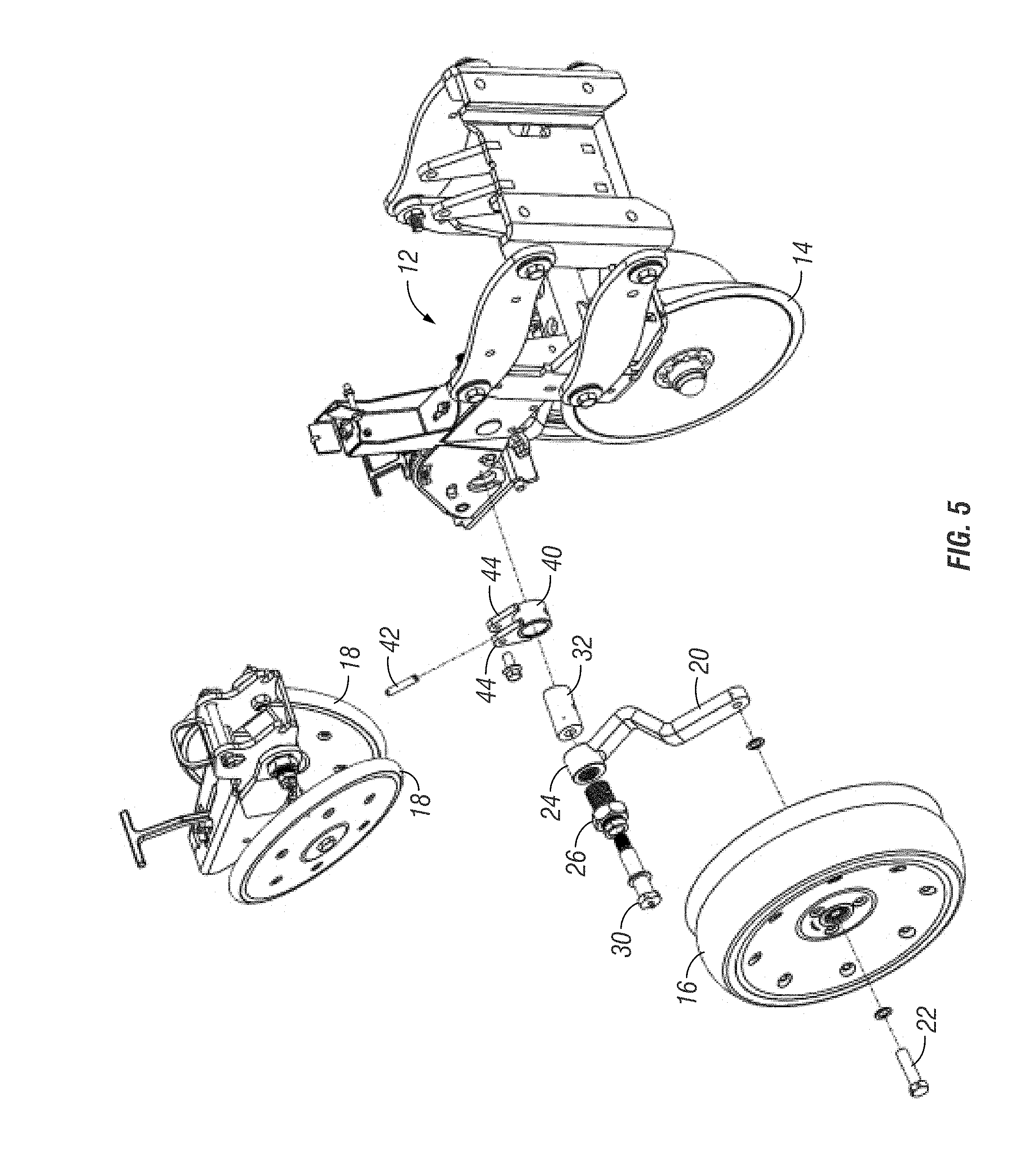
| Appl. No.: | 16/222451 | ||||||||||
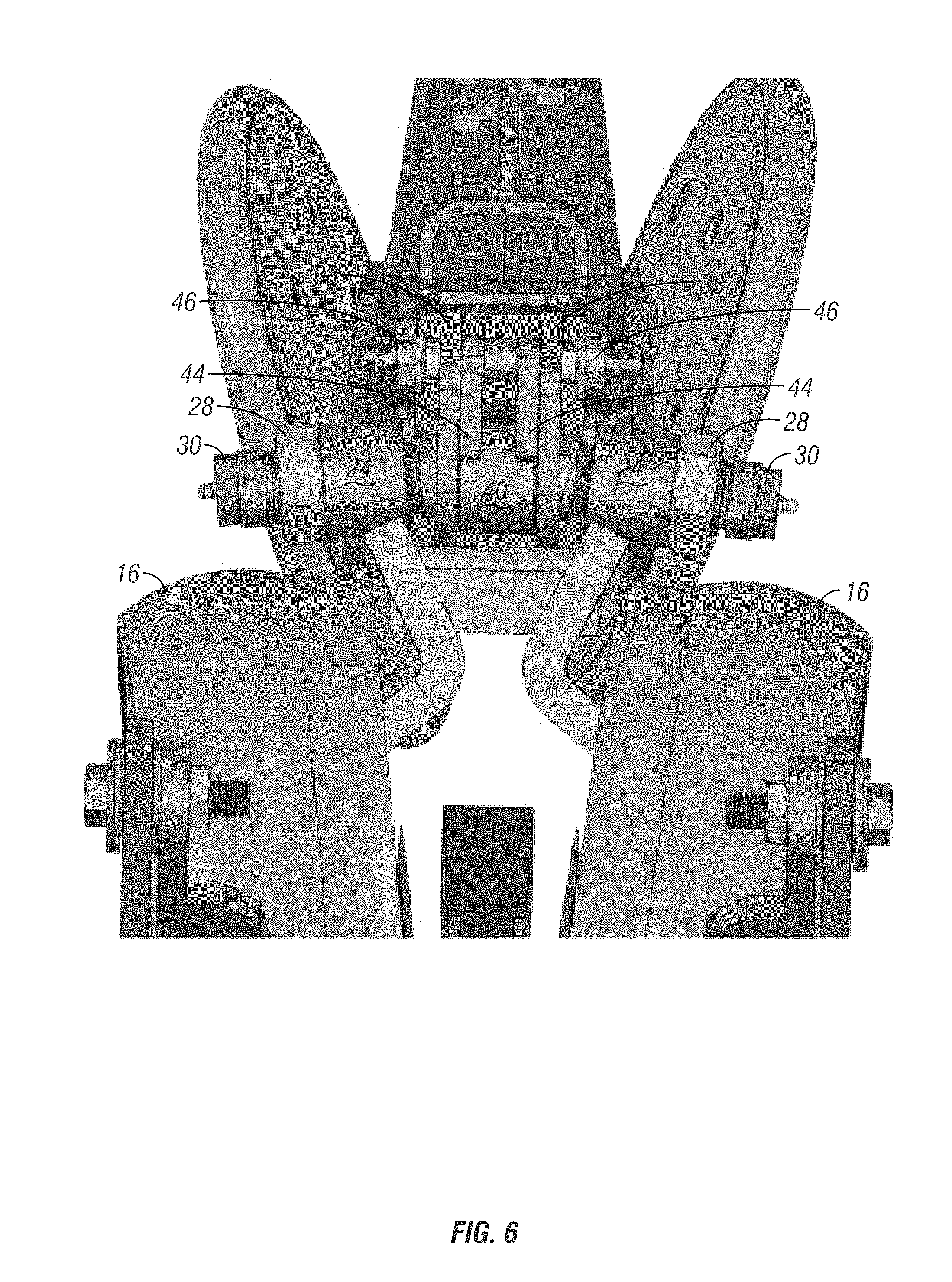
| Filed: | December 17, 2018 |
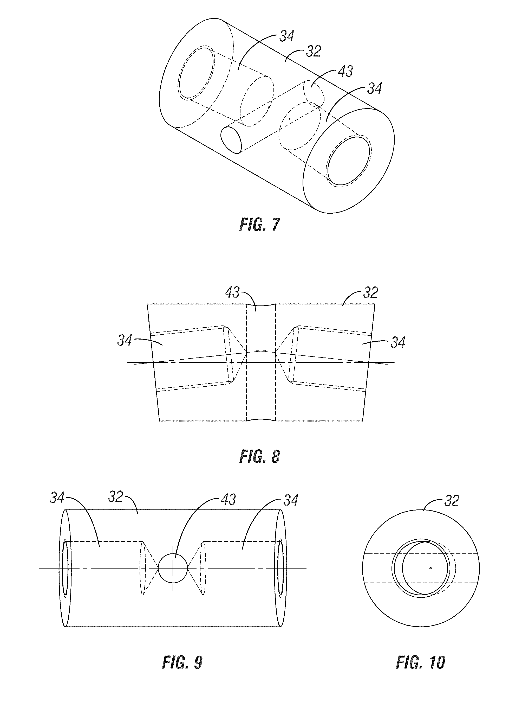
Related U.S. Patent Documents
| Application Number | Filing Date | Patent Number | ||
|---|---|---|---|---|
| 15493382 | Apr 21, 2017 | |||
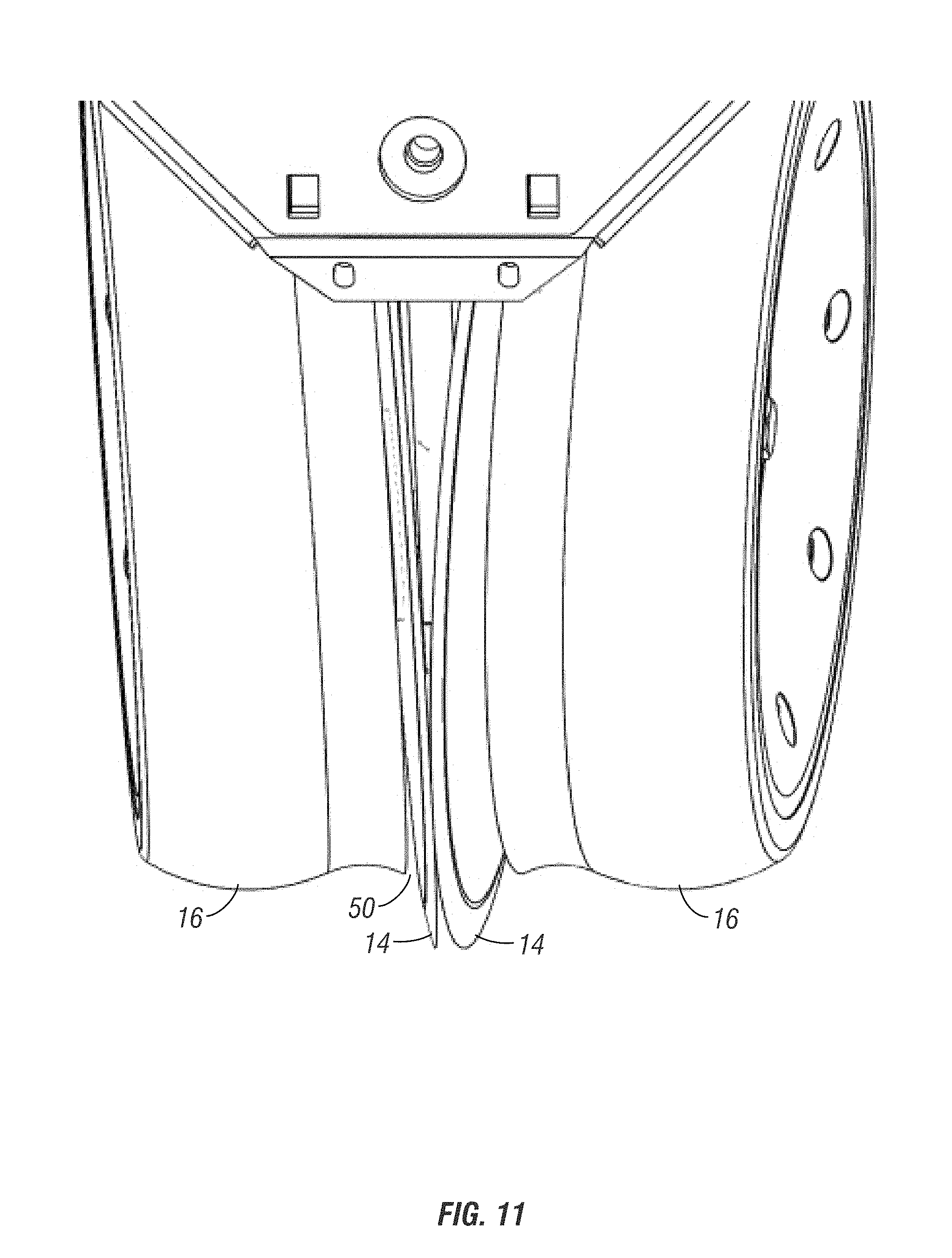
| 16222451 | ||||
| 62326063 | Apr 22, 2016 | |||
| Current U.S. Class: | 1/1 |
| Current CPC Class: | A01C 7/203 20130101; A01C 5/064 20130101; A01C 7/201 20130101; A01B 71/04 20130101; A01B 63/163 20130101; A01C 5/068 20130101 |
| International Class: | A01C 7/20 20060101 A01C007/20; A01C 5/06 20060101 A01C005/06 |
Claims
1. A row planter, comprising: a frame, a pair of discs on the frame to form a furrow in the ground; a pair of gauge wheels adjutably mounted on the frame; and each gauge wheel having an adjustable camber.
2. The row planter of claim 10 wherein the gauge wheels are laterally adjustable relative to the discs.
3. The row planter of claim 1 further comprising a tubular member pivotal about a horizontal axis and having a pair of arms bolted to the frame via a slot in the frame and a pair of bolts extending through the arms and the slot to permit the camber adjustment of the gauge wheels.
4. The row planter of claim 3 wherein the tubular member resides between the gauge wheels.
5. The row planter of claim 1 wherein each of the gauge wheels includes an adjustment bushing to allow lateral adjustment of the wheels.
6. The row planter of claim 5 wherein each gauge wheel includes a pivot bushing extending into the adjustment bushing.
7. The row planter of claim 6 wherein each pivot bushing includes a grease zerk.
8. The row planter of claim 6 wherein each pivot bushing is threadably coupled to a center shaft.
9. The row planter of claim 6 wherein each pivot bushing pivots about a non-horizontal axis.
10. A row planter, comprising: a frame with a pair of gauge wheels; a pair of arms to mount the gauge wheels to the frame; each arm having a first end to which one gauge wheel is bolted and a second end coupled to the frame so that the angular orientation of the arm to the frame is variable such that the gauge wheel has an adjustable camber.
11. The row planter of claim 10 further comprising a tubular member mounted to slots in the frame and the second end of each arm being operatively connected to the tubular member.
12. The row planter of claim 11 wherein the tubular member is movable along the slot to change the camber of the gauge wheel.
13. The row planter of claim 12 further comprising bolts extending through the slots and into the tubular member to fix the tubular member in a selected position when the bolts are tightened.
14. The row planter of claim 13 wherein the tubular member has a pair of arms to threadably receive the bolts.
15. The row planter of claim 10 wherein the gauge wheels are laterally adjustable.
16. The row planter of claim 15 further comprising an adjustment bushing threadably extending into the second end of the arm.
17. The row planter of claim 16 further comprising a pivot bolt extending through the adjustment bushing for receipt in a mounting shaft operatively connected to the frame.
18. The row planter of claim 10 wherein the camber of the gauge wheels is adjusted in unison.
Description
CROSS-REFERENCE TO RELATED APPLICATION
[0001] This is a divisional application of U.S. Ser. No. 15/493,382, filed Apr. 21, 2017, which claims priority to provisional application U.S. Ser. No. 62/326,063, filed Apr. 22, 2016, all of which are herein incorporated by reference in their entirety.
BACKGROUND OF THE INVENTION
[0002] Row planter units are precision tools used in farming to plant high tech seeds at uniform depth and spacing to ensure the highest yield potential. To achieve maximum results, the row planter unit must be properly maintained and periodically adjusted.
[0003] Row planter units typically include a pair of angularly disposed opening discs to form a V-shaped opening or furrow in the soil into which seeds are planted. The disc openers are followed by a pair of gauge wheels that control the depth of the furrow opened by the discs, and aid in holding the V-shaped profile of the furrow. The gauge wheels are mounted on pivoting arms, which include bushings. The gauge wheels are parallel to and are closely spaced to the discs, or contact the disc openers, when properly positioned, to prevent the buildup of dirt or trash between the gauge wheels and the opening discs. Over time, the bushings wear, which causes the gauge wheel angles to change and allow the gauge wheels to move away from the disc openers. As the bushings wear, the disc openers spread apart, forming a gap between the disc openers. The gap leads to deterioration of the V-shaped seed furrow profile, which is extremely undesirable, and which ultimately adversely affects yield.
[0004] One known method for adjusting the gauge wheels to maintain proper positioning is to provide washers or shims which can be added or removed. The washers or shims are positioned adjacent to the upper end of the gauge wheel arm to provide minimum clearance between the gauges wheel and the sides of the discs. This adjustment method necessarily requires removal of the gauge wheel and the gauge wheel arm, such that the shims can be added or removed, as needed. This operation is time consuming and may be difficult if the wheel retaining bolt is corroded or the head is stripped.
[0005] Therefore, a primary objective of the present invention is the provision of a row unit having laterally adjustable gauge wheels and wherein the gauge wheels have adjustable camber.
[0006] Another objective of the present invention is the provision of a row unit having gauge wheels which can be quickly and easily adjusted for proper positioning relative to the disc openers.
[0007] A further objective of the present invention is the provision of a row planter unit having gauge wheels whose lateral position and camber can be adjusted.
[0008] Still another objective of the present invention is the provision of a method for quickly and easily adjusting the lateral position of row planter gauge wheels relative to the opening discs.
[0009] Yet another objective of the present invention is the provision of a method for quickly and easily adjusting the camber of the gauge wheels on a row planter.
[0010] A further objective of the present invention is the provision of a row planter having a wear bushing to permit lateral adjustment of the gauge wheels relative to the opening discs.
[0011] Still another objective of the present invention is the provision of a means for adjusting the lateral position and camber orientation of row planter gauge wheels which is economical to manufactured, easy to install and use, and durable and safe in use.
[0012] These and other objectives will become apparent from the following description of the invention.
SUMMARY OF THE INVENTION
[0013] A row planter gauge wheel assembly is provided with the ability to quickly and easily adjust the gauge wheels relative to the opening discs on the row planter frame. Each gauge wheel is mounted on a pivotal arm. The upper end of each arm is mounted on a bushing assembly, including a pivot bushing extending into a threaded adjustment bushing. A nut on the adjustment bushing can be loosened to allow quick lateral adjustment of each gauge wheel.
[0014] The gauge wheel camber can also be adjusted via a rotatable collar mounted on the gauge wheel mounting shaft.
DESCRIPTION OF THE DRAWINGS
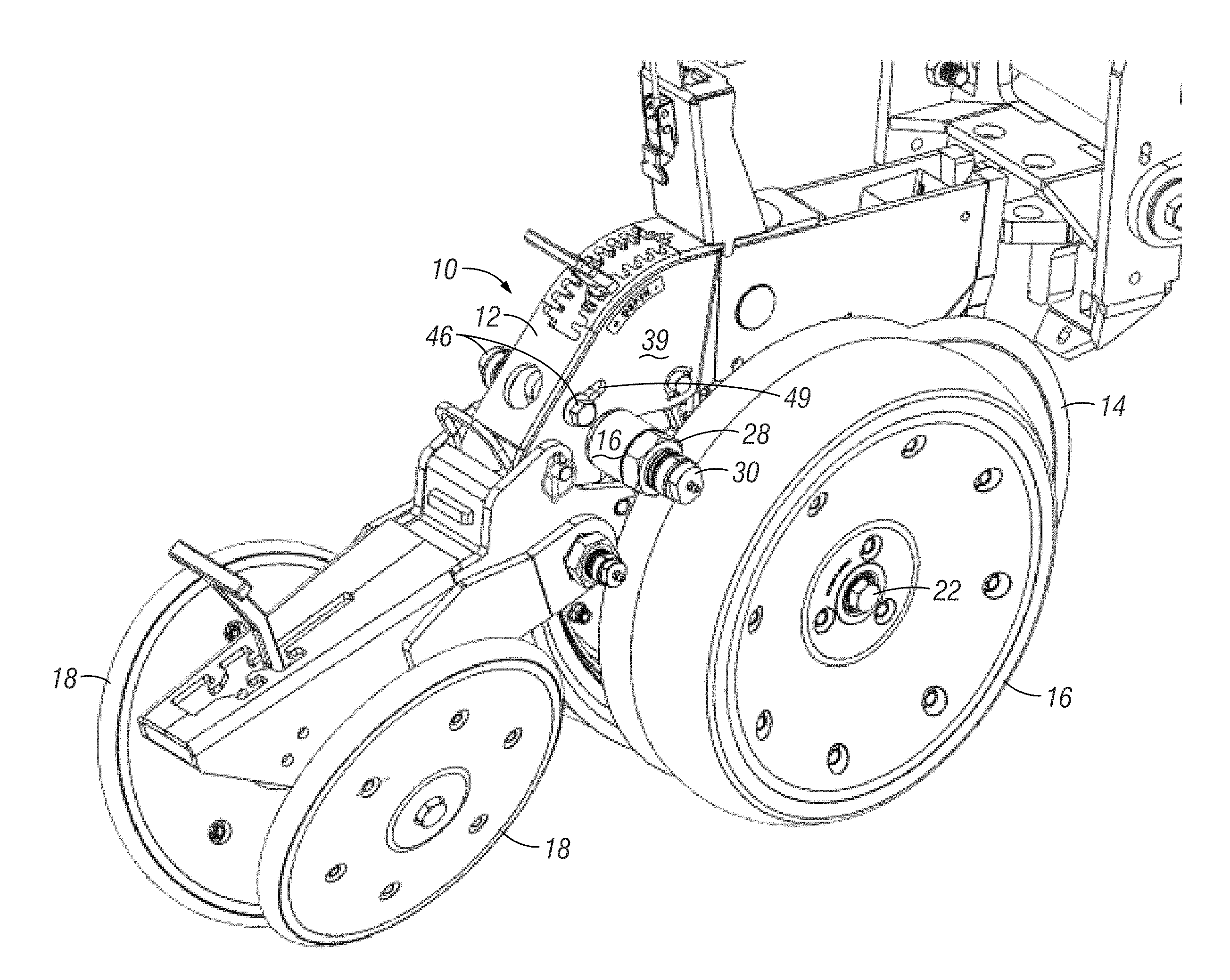
[0015] FIG. 1 is a perspective view of a row planter unit with disc openers, gauge wheels, and closing wheels.
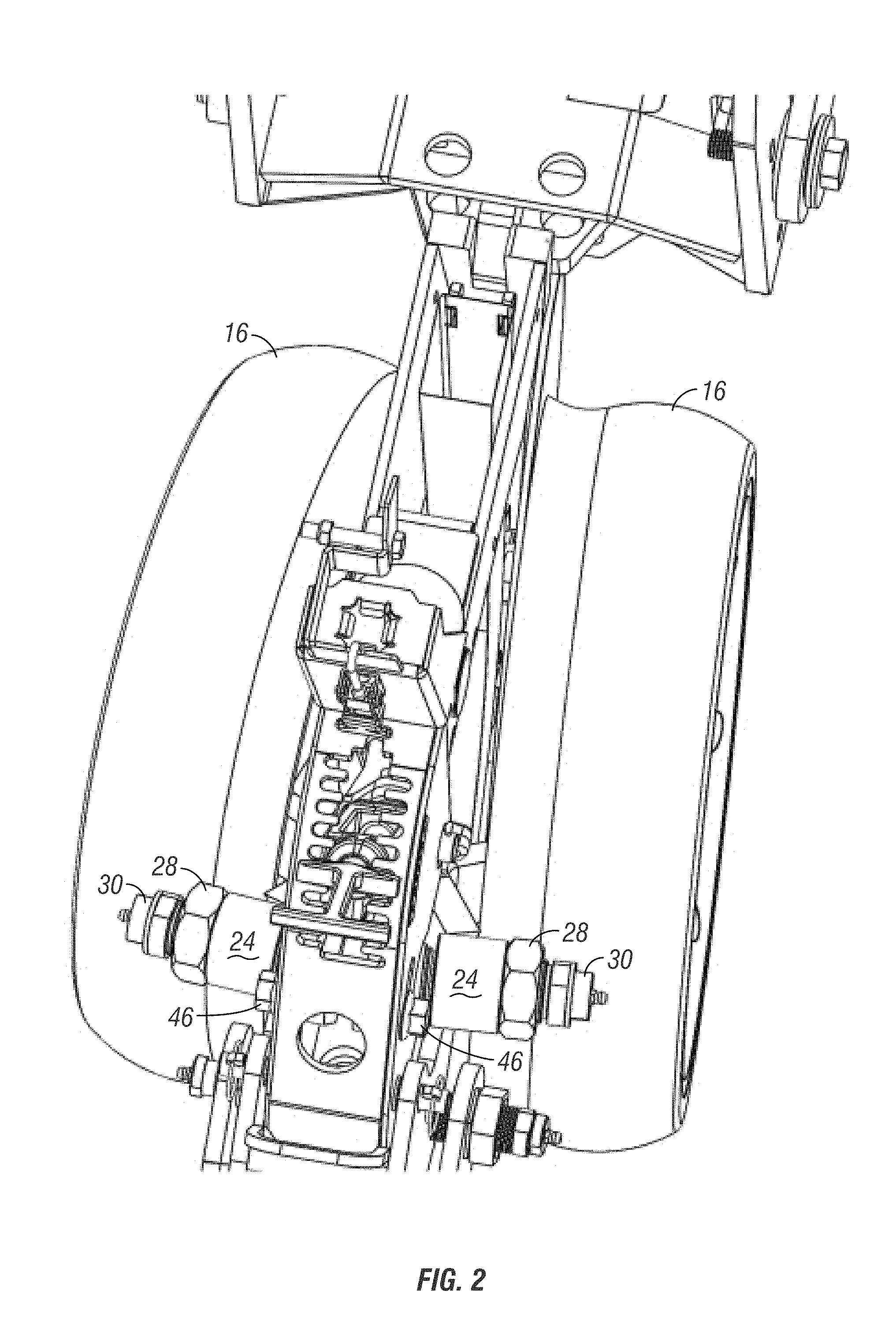
[0016] FIG. 2 is a top plan view of the row planter unit shown in FIG. 1.
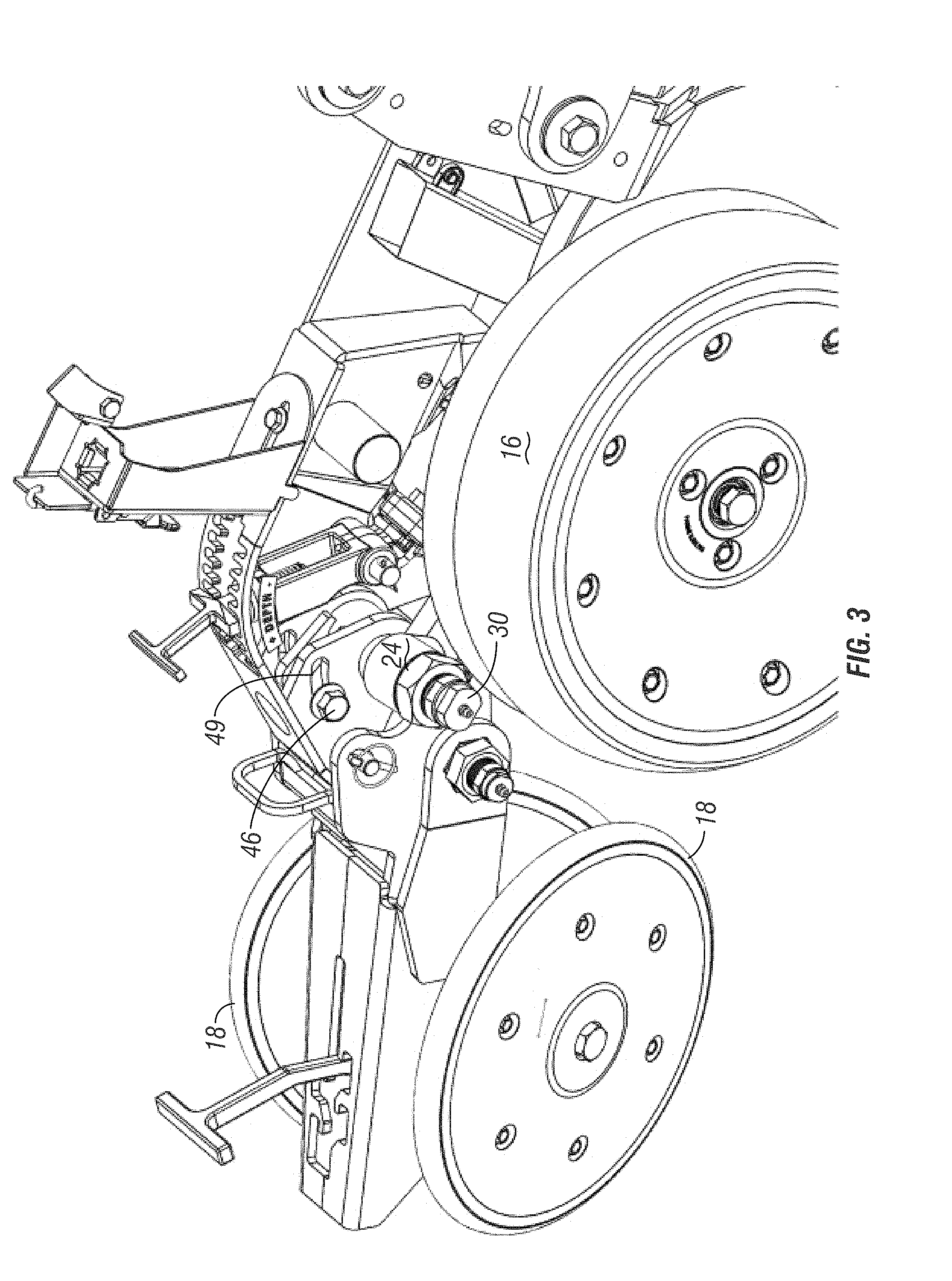
[0017] FIG. 3 is another perspective view of the row planter unit shown in FIG. 1.
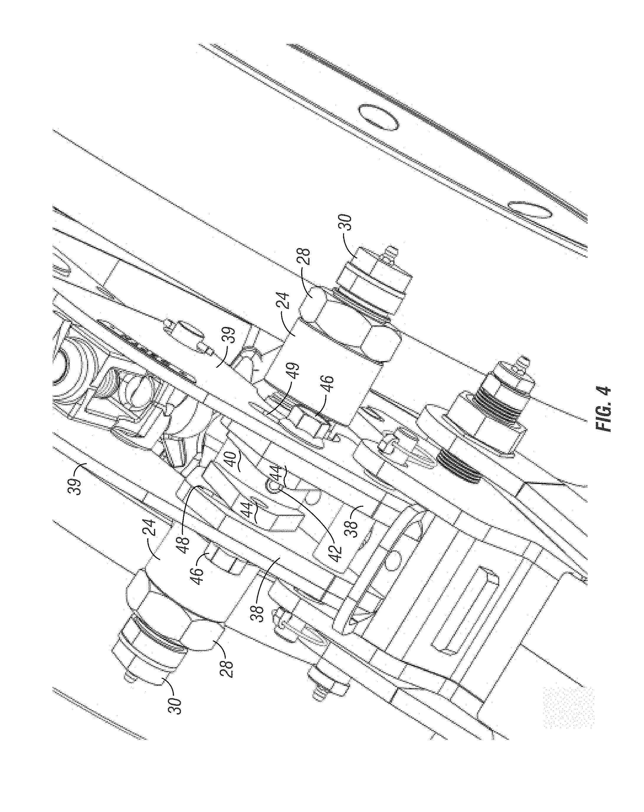
[0018] FIG. 4 is an enlarged upper perspective view of the row planter unit shown in FIG. 1.
[0019] FIG. 5 is a partially exploded perspective view of the row planter unit shown in FIG. 1.
[0020] FIG. 6 is an enlarged plan view showing the means for lateral adjustment and camber adjustment of the gauge wheels of the row planter unit.
[0021] FIG. 7 is a perspective view of the gauge wheel mounting shaft.
[0022] FIG. 8 is a front elevation view of the mounting shaft.
[0023] FIG. 9 is a top plan view of the mounting shaft.
[0024] FIG. 10 is an end elevation view from one end of the mounting shaft.
[0025] FIG. 11 is a front elevation view showing the gauge wheels in proper position relative to the disc openers.
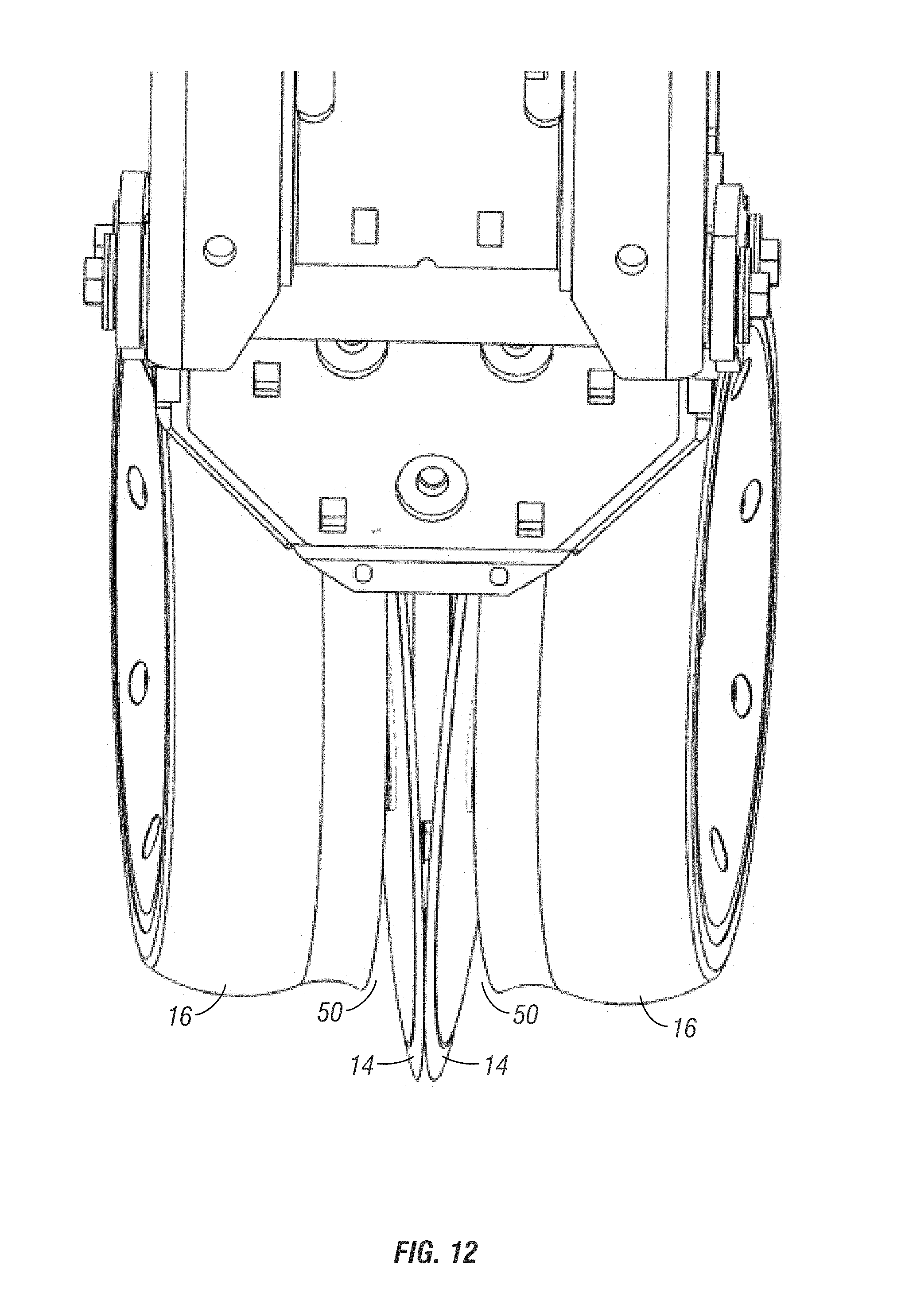
[0026] FIG. 12 is a front elevation view showing the position of the gauge wheels after bushing wear, with a gap between the gauge wheels and the opener discs.
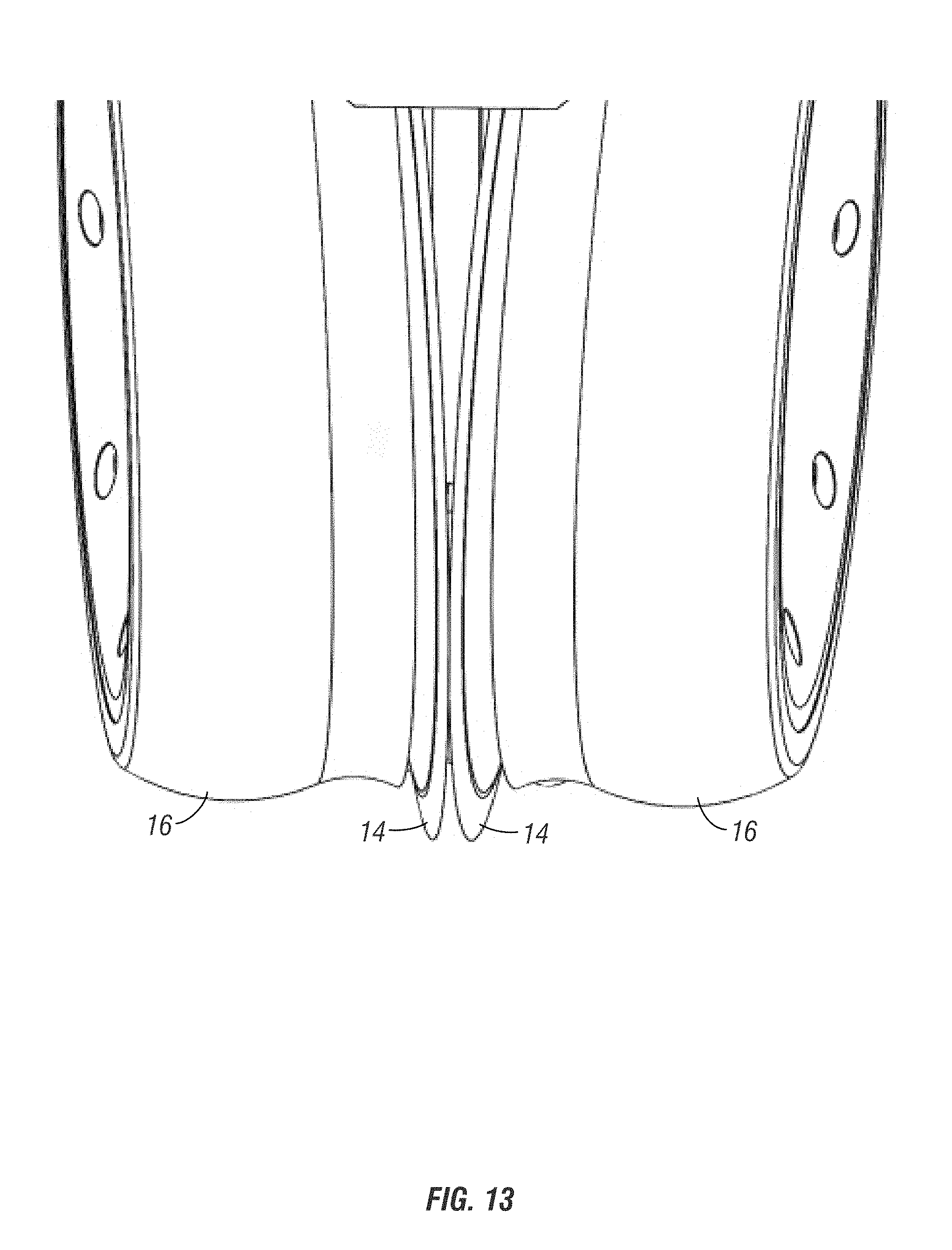
[0027] FIG. 13 is another front elevation view showing correctly adjusted gauge wheels parallel to the disc openers.
DETAILED DESCRIPTION OF THE INVENTION
[0028] A row planter unit having the adjustable gauge wheels of the present invention is generally designated in the drawings by the reference numeral 10. The unit 10 includes a frame 12, a pair of disc openers (or opening discs) 14, a pair of gauge wheels 16, and a pair of closing wheels 18. The discs 14 and closing wheels 18 are conventional, and do not form a part of the present invention.
[0029] Applicant's invention is directed towards the gauge wheels 16, and more specifically, to the ability to adjust the camber and the lateral position of the gauge wheels 16.
[0030] As best seen in the partial exploded view of FIG. 5, each gauge wheel 16 is mounted on a lower end of an arm 20 via a bolt 22 which defines the rolling axis for the wheel. The upper end of the arm 20 is adjustably coupled to the frame 12 by a bushing assembly. More particularly, the upper end of the arm 20 has an internally threaded collar 24 which threadably receives a lateral adjustment bushing 26. The bushing 26 has external threads to threadably mate with the internal threads on the collar 24 of the arm 20. A lock nut 28 on the bushing 26 fixes the threaded position of the bushing 26 in the collar 24 of the arm 20, thereby allowing the lateral position of the gauge wheel 16 to be adjusted relative to the opening disc 14.
[0031] A pivot bushing 30 extends through the adjustment bushing 26 and has an inner end which is threadably received within a mounting shaft 32. The pivot bushing 30 allows the adjustment bushing 26, the fixed arm 20 and the gauge wheel 16 to pivot about the axis of the bushing 30 as the row unit travels through the field. Preferably, the bushing 30 is hollow, with an end grease zerk 31, which allows the inside of the bushing 26 to be greased, thereby minimizing wear between the bushings 26 and 30.
[0032] The opposite gauge wheel is similarly mounted to the opposite end of the mounting shaft 32 via a mirror image arm 20, adjustment bushing 26, and pivot bushing 30.
[0033] As seen in FIG. 8, the shaft 32 has internally threaded bores 34 on each end which are angularly disposed with respect to each other. The bores 34 receive the threaded ends 33 of the pivot bushing 30. While FIG. 8 shows the angular orientation of the bores 34 to be 6 degrees relative to horizontal, it is understood that this angle can be increased or decreased without departing from the scope of the present invention.
[0034] As seen in FIG. 6, the frame 12 includes a pair of spaced apart, longitudinally extending inner plates 38 and outer plates 39. A tubular member 40 resides between the plates 38. The mounting shaft 32 extends through the tubular member 40, and is affixed thereto by a roll pin 42. The tubular member 40 has a pair of arms 44 welded thereto and extending rearwardly between the plates 38. A pair of bolts 46 extend through aligned slots 48, 49 in the inner and outer plates 38, 39 and are threadably received in the arms 44 of the tubular member 40. When the bolts 46 are loosened, the tubular member 40 can be rotated about its axis, thereby adjusting the camber of the gauge wheels 16. The bolts 46 are tightened to maintain the selected camber position of the gauge wheels 16.
[0035] FIG. 13 shows the gauge wheels 16 properly adjusted so as to be parallel to and closely spaced to, or lightly engaging the opening discs 14. In comparison, FIGS. 11 and 12 show the gauge wheels on worn bushings before any adjustments, with gaps 50 between the gauge wheels 16 and the discs 14. The gaps 50 cause mis-formed or deterioration of the seed furrow, and thus reduced yield. Dirt and trash can also accumulate in the gaps 50.
[0036] The properly adjusted gauge wheels 16, as shown in FIG. 13, maintain proper furrow creation, for proper seed placement and enhanced yield, and eliminate or minimize buildup of dirt and trash.
[0037] The invention has been shown and described above with the preferred embodiments, and it is understood that many modifications, substitutions, and additions may be made which are within the intended spirit and scope of the invention. From the foregoing, it can be seen that the present invention accomplishes at least all of its stated objectives.
* * * * *
D00000
D00001
D00002
D00003
D00004
D00005
D00006
D00007
D00008
D00009
D00010
XML
uspto.report is an independent third-party trademark research tool that is not affiliated, endorsed, or sponsored by the United States Patent and Trademark Office (USPTO) or any other governmental organization. The information provided by uspto.report is based on publicly available data at the time of writing and is intended for informational purposes only.
While we strive to provide accurate and up-to-date information, we do not guarantee the accuracy, completeness, reliability, or suitability of the information displayed on this site. The use of this site is at your own risk. Any reliance you place on such information is therefore strictly at your own risk.
All official trademark data, including owner information, should be verified by visiting the official USPTO website at www.uspto.gov. This site is not intended to replace professional legal advice and should not be used as a substitute for consulting with a legal professional who is knowledgeable about trademark law.