Authentication System For Electronic Control Unit On A Bus
Markham; Thomas R. ; et al.
U.S. patent application number 15/784044 was filed with the patent office on 2019-04-18 for authentication system for electronic control unit on a bus. The applicant listed for this patent is Honeywell International Inc.. Invention is credited to Alexander Chernoguzov, Thomas R. Markham.
| Application Number | 20190116045 15/784044 |
| Document ID | / |
| Family ID | 63857705 |
| Filed Date | 2019-04-18 |


View All Diagrams
| United States Patent Application | 20190116045 |
| Kind Code | A1 |
| Markham; Thomas R. ; et al. | April 18, 2019 |
AUTHENTICATION SYSTEM FOR ELECTRONIC CONTROL UNIT ON A BUS
Abstract
An authentication system having a communications bus, a transmitter connected to the bus, and a receiver connected to the bus. A physical layer signal may be applied by the transmitter to a message on the bus for authenticating the transmitter. The physical layer signal may incorporate an identifier (ID) of the transmitter. The receiver may receive the message and decode the physical layer signal on the message. Decoding the physical layer signal on the message may reveal the ID of the transmitter sending the message. The receiver may look up the ID on a list of IDs corresponding to transmitters approved to send the message, to determine whether the ID of the transmitter sending the message matches an ID on the list. Only if the ID of the transmitter matches an ID on the list, then the transmitter may be authenticated and authorized to send the message.
| Inventors: | Markham; Thomas R.; (Fridley, MN) ; Chernoguzov; Alexander; (Warrington, PA) | ||||||||||
| Applicant: |
|
||||||||||
|---|---|---|---|---|---|---|---|---|---|---|---|
| Family ID: | 63857705 | ||||||||||
| Appl. No.: | 15/784044 | ||||||||||
| Filed: | October 13, 2017 |
| Current U.S. Class: | 1/1 |
| Current CPC Class: | H04L 1/0061 20130101; H04L 12/40019 20130101; H04L 63/0876 20130101; G06F 13/4282 20130101; H04L 2012/40215 20130101; H04L 63/06 20130101; H04L 63/123 20130101; H04L 63/101 20130101; H04L 63/20 20130101; H04L 63/1416 20130101; H04L 63/164 20130101; H04L 9/3234 20130101; H04L 12/40104 20130101 |
| International Class: | H04L 9/32 20060101 H04L009/32; H04L 12/40 20060101 H04L012/40; H04L 29/06 20060101 H04L029/06; G06F 13/42 20060101 G06F013/42; H04L 1/00 20060101 H04L001/00 |
Claims
1. An authentication system comprising: a bus; a transmitter connected to the bus; and a receiver connected to the bus; and wherein: a physical layer signal is applied by the transmitter to a message on the bus for authenticating the transmitter; the physical layer signal incorporates an identifier (ID) of the transmitter; the receiver receives the message and decodes the physical layer signal on the message; a decoding of the physical layer signal on the message reveals the ID of the transmitter sending the message; the receiver looks up the ID on a list of IDs corresponding to transmitters approved to send the message, to determine whether the ID of the transmitter sending the message matches an ID on the list; and if the ID of the transmitter matches an ID on the list, then the transmitter is authenticated and authorized to send the message.
2. The system of claim 1, wherein: if the transmitter is authenticated, the message sent by the transmitter that is received by the receiver is processed by the receiver; and if the transmitter cannot be authenticated, then the message sent by the transmitter that is received by the receiver is blocked and not processed by the receiver.
3. The system of claim 1, wherein a message having a physical layer signal, can be received by the receiver without interference to an ability of the receiver to receive and decode another message that is a normal signal digitized data message per a communications standard.
4. The system of claim 1, wherein: the bus is a controller area network (CAN); the message is a CAN message; the CAN message has a dominant portion and a recessive portion; and the physical layer signal is applied to a dominant portion, a recessive portion, or both a dominant and a recessive portion of the CAN message; or wherein one or more media are selected from a group comprising wired media, optical media, radio frequency media, used singularly or in combination.
5. The system of claim 1, wherein the bus comprises one or more additional receivers that detect the blocking of the message by the receiver that checks the ID decoded from the physical layer signal on the message from the transmitter and determines that the ID of the transmitter does not match an ID on a list of IDs corresponding to transmitters approved to send the message, and in turn blocks the message.
6. The system of claim 1, wherein only one receiver on the bus needs to receive the message and decode the physical layer signal applied to the message.
7. The system of claim 1, wherein if a transmitter is authorized to transmit a message, the receiver allows the message to be processed without interfering with the message.
8. The system of claim 2, wherein if the transmitter is not authorized to transmit a message, according to an ID check, then the receiver blocks a processing of the message by asserting a signal on the bus that causes a cyclic redundancy code (CRC) associated with the message to be corrupted.
9. The system of claim 8, wherein one or more nodes on the bus having receivers detect corruption of the CRC associated with the message and thus do not process the message.
10. The system of claim 2, wherein two or more receivers on the bus can receive and decode a physical layer signal on the message to obtain an ID of the transmitter of the message and determine whether the ID matches an ID on a list of IDs of transmitters authorized to send the message.
11. The system of claim 10 wherein: if the any one of the two or more receivers determines that the transmitter is authorized to transmit the message, then the any one of the two or more receivers will allow the message to be processed by a local processor; and if the any one of the two or more receivers determines that the entity was not authorized to transmit the message, then the any one of the two or more receivers will block a processing of the message by the local processor.
12. The system of claim 1, wherein: the transmitter applies a modulated signal to the physical layer signal to code an ID for authentication of the transmitter; and one or more modulation types are be selected from a group comprising frequency shift keying (FSK), amplitude shift keying, (ASK) on/off keying (OOK), phase shift keying (PSK), quadrature phase shift keying (QPSK), quadrature amplitude modulation (QAM) and continuous phase modulation (CPM).
13. The system of claim 1, wherein the bus comprises one of the following receiver and transmitter combinations of components: one or more authenticating receivers, and one or more authenticating transmitters; one or more authenticating receivers, one or more authenticating transmitters, and one or more non-authenticating receivers; one or more authenticating receivers, one or more authenticating transmitters, and one or more non-authenticating transmitters; one or more authenticating receivers, one or more authenticating transmitters, one or more non-authenticating receivers, and one or more mon-authenticating transmitters; only one authenticating receiver and only one authenticating transmitter; only one authenticating receiver, only one authenticating transmitter, and one or more non-authenticating receivers; only one authenticating receiver, only one authenticating transmitter, and one or more non-authenticating transmitters; or only one authenticating receiver, only one authenticating transmitter, one or more non-authenticating receivers, and one or more non-authenticating transmitters.
14. The system of claim 13, wherein a receiver and transmitter combination that has components that perform authenticating functions and non-authenticating functions interoperate in accordance with a security policy applied by one or more authenticating components.
15. An authentication method comprising: applying a physical layer authentication signal to a message to be sent by a transmitter on a bus; decoding an identifier (ID) from the physical layer authentication signal on the message to be received by a receiver on the bus; and looking up the ID on a list of IDs corresponding to transmitters approved to send the message, to determine whether the ID decoded from the physical layer authentication signal matches an ID on the list; and wherein: if the ID matches an ID on the list, then the message on the bus is authorized; and if the ID matches no ID on the list, then the message on the bus is unauthorized.
16. The method of claim 15, further comprising: accepting and processing the message on the bus if the message is authorized; and blocking the message on the bus if the message on the bus is unauthorized.
17. The method of claim 16, wherein only one receiver on the bus receives the message and decodes the physical layer authentication signal applied to the message.
18. A mechanism for authenticating transmissions, comprising: a transmitting entity; a receiving entity; and a bus connected to the transmitting entity and the receiving entity; wherein: a physical layer signal is applied by the transmitting entity to a message on the bus to authenticate the transmitting entity; the physical layer signal incorporates an identifier (ID) of the transmitting entity; the receiving entity receives the message and decodes the physical layer signal on the message; a decoding of the physical layer signal on the message reveals the ID of the transmitting entity sending the message; the receiving entity looks up the ID on a list of IDs corresponding to transmitting entities approved to send the message, to determine whether the ID of the transmitting entity sending the message matches an ID on the list; if the ID of the transmitting entity matches an ID on the list, then the transmitting entity is authenticated; and if the ID of the transmitting entity does not match an ID on the list, then the transmitting entity is not authenticated.
19. The mechanism of claim 18, wherein: if the transmitting entity is authenticated, the message sent by the transmitting entity that is received by the receiving entity is processed by the receiving entity; and if the transmitting entity is not authenticated, then the message sent by the transmitting entity that is received by the receiving entity is blocked and not processed by the receiving entity.
20. The system of claim 18, wherein a message having a physical layer signal, can be received by the receiving entity without interference to an ability of the receiving entity to receive and decode another message that is a normal signal digitized data message per a communications standard.
Description
BACKGROUND
[0001] The present disclosure pertains to preventing unauthorized messages in communication systems.
SUMMARY
[0002] The disclosure reveals an authentication system having a communications bus, a transmitter connected to the bus, and a receiver connected to the bus. A physical layer signal may be applied by the transmitter to a message on the bus for authenticating the transmitter. The physical layer signal may incorporate an identifier (ID) of the transmitter. The receiver may receive the message and decode the physical layer signal on the message. Decoding the physical layer signal on the message may reveal the ID of the transmitter sending the message. The receiver may look up the ID on a list of IDs corresponding to transmitters approved to send the message, to determine whether the ID of the transmitter sending the message matches an ID on the list. Only if the ID of the transmitter matches an ID on the list, then the transmitter may be authenticated and authorized to send the message.
BRIEF DESCRIPTION OF THE DRAWING
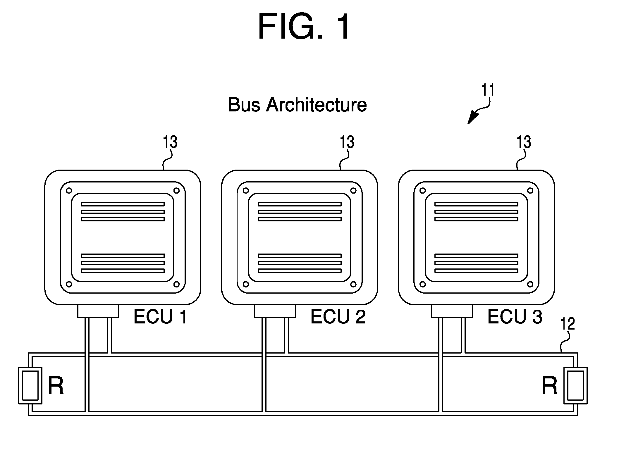
[0003] FIG. 1 is a diagram of what modern vehicles may incorporate in terms of on-board computing functions;
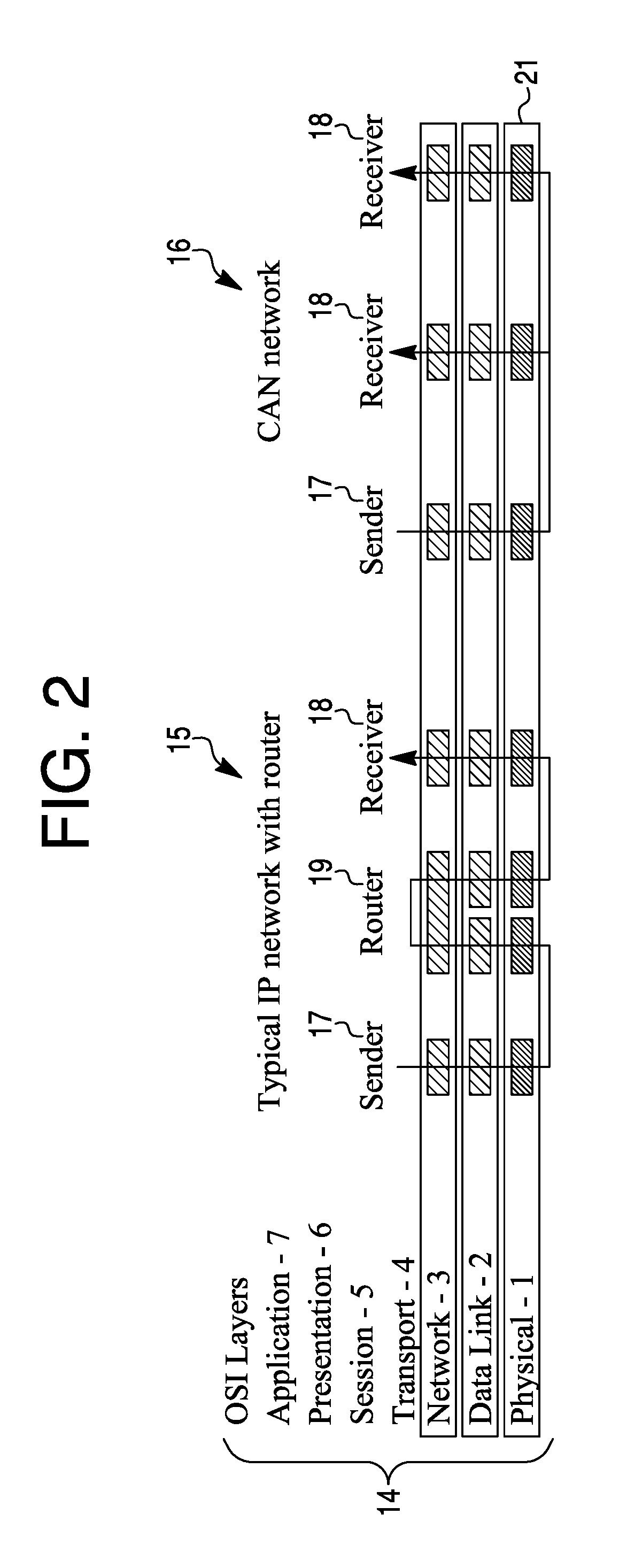
[0004] FIG. 2 is a diagram that contrasts a standard internet protocol environment with a controller area network bus environment;
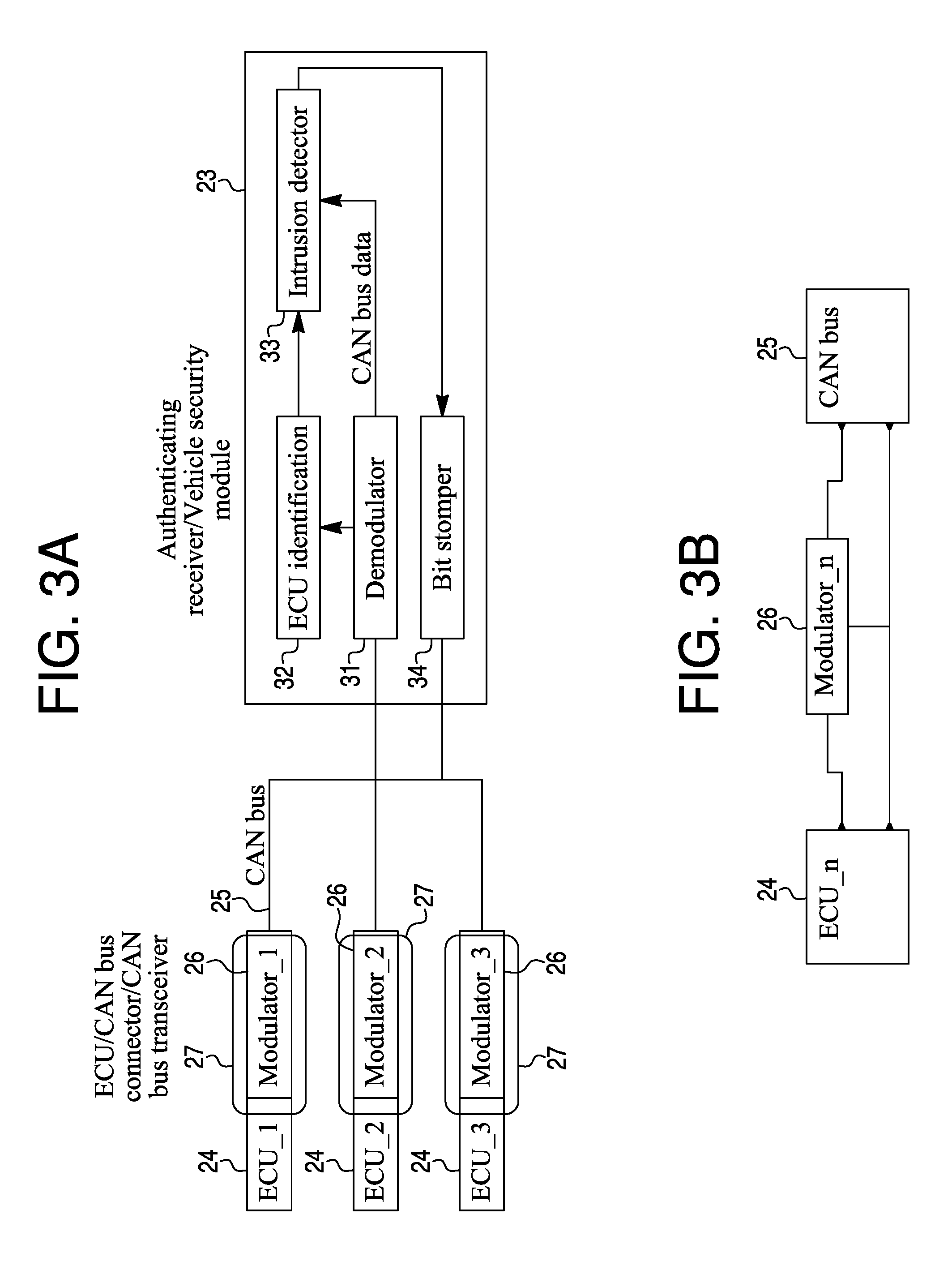
[0005] FIG. 3a is a diagram of an electronic control unit source authentication system;
[0006] FIG. 3b is a diagram of a simplified version of applying a unique signal to a message from an electronic control unit by a dedicated modulator;
[0007] FIG. 4 is a diagram of a bus incorporating a two-wire system;
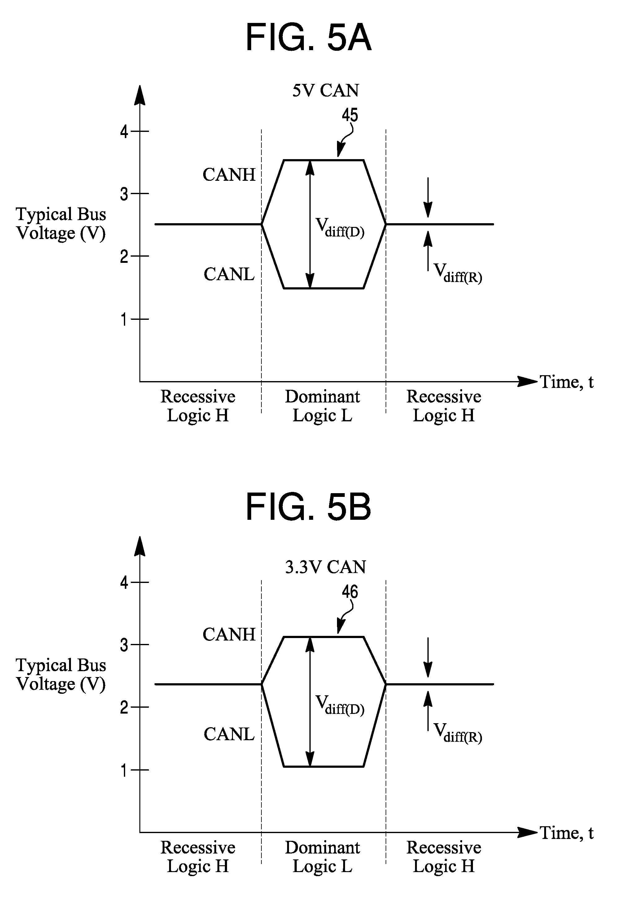
[0008] FIGS. 5a and 5b are diagrams of differential signals or voltages on a bus;
[0009] FIG. 6 is a diagram of a raw bus signal waveform without modulation;
[0010] FIG. 7 is a diagram of a representation of a modulated signal;
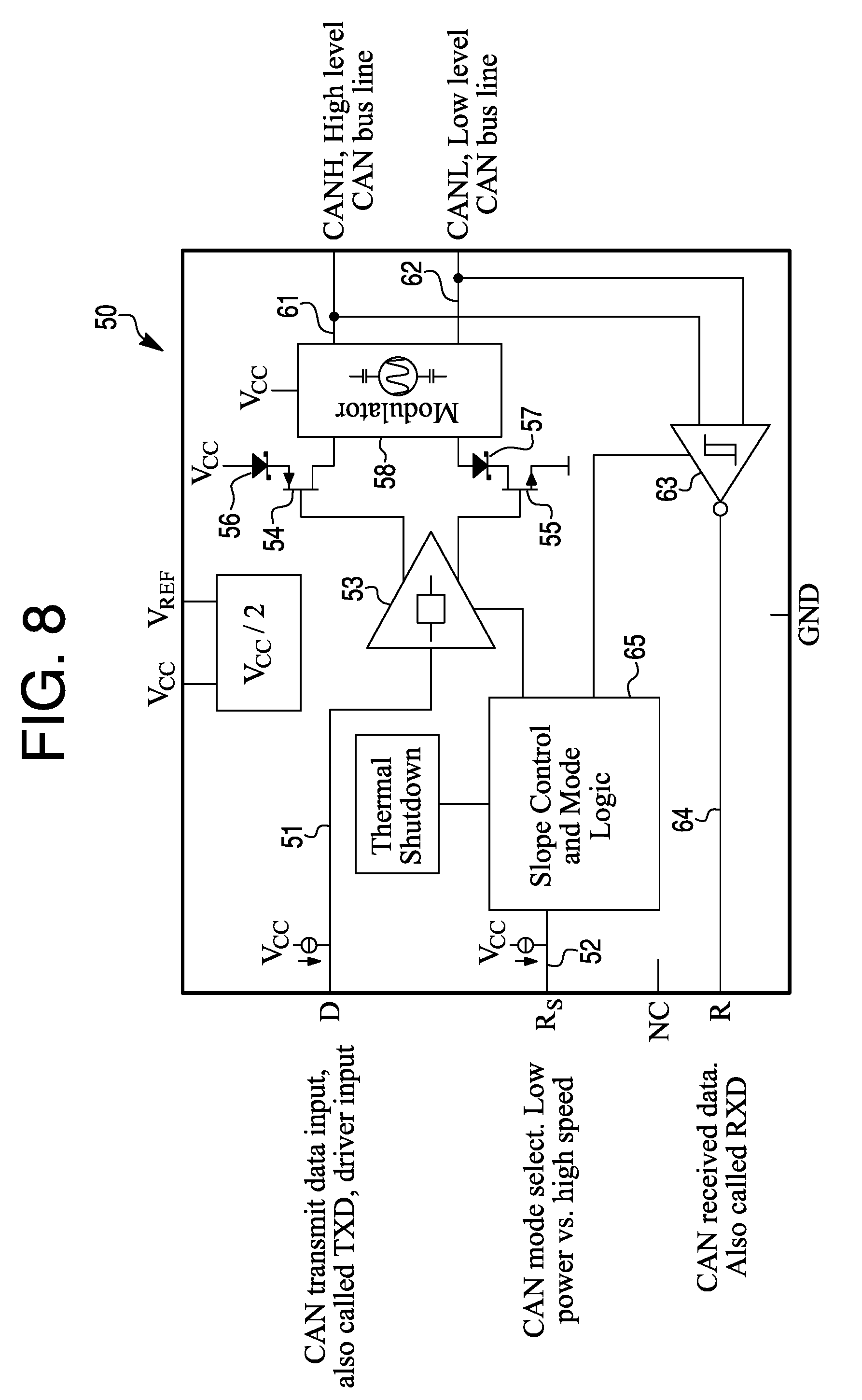
[0011] FIG. 8 is a diagram of a modulation scheme integrated within a transceiver on a chip;
[0012] FIG. 9 is a diagram of an electronic control unit fingerprint applied to a controller area network message;
[0013] FIG. 10 is a diagram of a controller area unit bus signal on an oscilloscope;
[0014] FIG. 11 is a diagram of a waveform having a recessive logic signal and a dominant logic signal;
[0015] FIG. 12 shows a diagram of a system for authentication of components for allowing transmission of messages;
[0016] FIGS. 13, 14 and 15 are diagrams of message packets used for timing analysis in aiding of determining authentication with transmission and decoding in order to prevent a successful transmission of messages from unauthorized sources;
[0017] FIG. 16 is a diagram of a transmit portion of an example of the present system; and
[0018] FIG. 17 is a diagram of a receiving portion of an example of the present system.
DESCRIPTION
[0019] The present system and approach may incorporate one or more processors, computers, controllers, user interfaces, wireless and/or wire connections, and/or the like, in an implementation described and/or shown herein.
[0020] This description may provide one or more illustrative and specific examples or ways of implementing the present system and approach. There may be numerous other examples or ways of implementing the system and approach.
[0021] Aspects of the system or approach may be described in terms of symbols in the drawing. Symbols may have virtually any shape (e.g., a block) and may designate hardware, objects, components, activities, states, steps, procedures, and other items.
[0022] Authentication system and approach for electronic control unit on a bus may involve electronic control unit (ECU) radio frequency (RF) identification. A present system may integrate some of the identification/authentication functions into a transceiver in order to reduce costs.
[0023] The present system and approach may use controller area network (CAN) herein for illustrative purposes, but instead media such as other wired media, optical media, radio frequency media, or so on, may be used singularly or in combination.
[0024] A CAN based bus used within the automotive environment does not necessarily appear to provide source authentication of messages on the bus. This may be a security issue. Cryptographic methods of providing source authentication may be problematic due to protocol restrictions and the complexities of key management in the repair environment.
[0025] A feature of the present system can be unique because it may eliminate a need for costly and complex cryptographic key management. The system may provide an ability to authenticate the sources of a message on the CAN bus. This may in turn allow a higher level of security for connected cars and self-driving cars (aka, highly automated vehicles).
[0026] This system may draw licensing revenue if offered to CAN bus transceiver vendors. There may be a market for companies to offer a CAN intrusion detection system (IDS) with a capability that may differentiate it from other systems.
[0027] The present system may add a modulator function to the CAN bus transceiver such that each node on the network applies a unique analog fingerprint to the messages it sends. A secure/authenticating receiver may then check the message type and fingerprint to ensure that the message is from an authorized source. If the message is not from an authorized source, the authenticating receiver may block the message in such a way that all other ECUs on the bus also reject the unauthorized message.
[0028] The present system may have an embedded software type. The software may run in a device/unit (e.g., firmware).
[0029] A CAN transceiver vendor may be available, such as Texas Instruments or NXP. The system may improve automotive software CAN bus intrusion detection.
[0030] Modern vehicles may incorporate on-board computing functions (e.g., electronic control units (ECUs) 13 connected by a controller area network (CAN) bus 12 as shown by architecture 11 in FIG. 1. The CAN bus may be a non-authenticated broadcast bus. This means that any ECU on the bus may send a message and other ECUs on the bus may assume that the message came from the proper source and may act upon the message.
[0031] Hackers have demonstrated the ability to hack into such systems in cars and interfere with critical functions such as braking and steering. Thus, vehicle manufacturers may be looking for a low-cost way to address the security issues. Some approaches may attempt to apply cryptography to CAN bus messages as a way of performing source authentication. There may be some issues associated with CAN bus encryption.
[0032] One issue may involve key management. When cryptography is used, each ECU may need a unique cryptographic key to allow the source of messages to be cryptographically authenticated. When a vehicle is produced in the factory, the original equipment manufacturer (OEM) may generate the keys and load them into the vehicle. However, when vehicle maintenance requires the replacement of a module, the new module needs to be loaded with the appropriate key. One may ask from where the new key comes. Many issues may be associated with obtaining a copy of the original key. There may be also issues if the module is loaded with a new randomly generated key. That implies that all other modules in the vehicle need to be updated to recognize the new key/module pair. Many security issues arise with attackers manipulating the key management system to extract real keys or to inject false keys. Given the number of years a vehicle may be in service and the range of repair options (dealers, independent shops, and owners), using new parts or parts from a salvage yard, key management may become complex and error prone.
[0033] Another issue may involve a cryptographic algorithm and mode. The issue with the CAN bus may be that the payload is only 8 bytes (64 bits). Thus, there may be issues using modern cryptographic algorithms such as the advanced encryption standard (AES) which operates on 128 bit blocks. One may consider using non-standard cryptographic algorithms and modes. However, history appears to be littered with cases of home grown cryptography being broken. An alternate approach may be using a newer CAN protocol, a flexible data rate (CAN-FD). This approach may permit for larger data frames and thus allow a use of strong cryptography. However, CAN-FD based approaches may still suffer from the key management issues noted above.
[0034] The present system may allow ECUs on the bus to authenticate to a secure gateway/vehicle security module without the need for cryptography. Thus, there may be no compatibility issues between cryptographic algorithms and the CAN protocol. So, the complexity of key management in the vehicle maintenance environment may be reduced or eliminated.
[0035] The present system may be different than other CAN bus authentication proposals in that it explicitly takes advantage of an unbroken physical layer (as defined by an open system interconnect (OSI), a seven-layer model 14 or similar model) among ECUs on a bus. A diagram of FIG. 2 may contrast a standard IP environment 15 with the CAN bus environment 16. Within a typical IP environment 15, there is not necessarily a continuous physical layer path between a sender 17 and receiver 18. Therefore, the physical layer signal may be received and regenerated by intermediate network nodes such as routers 19 and Ethernet switches 19. This may force the use of cryptography at a layer above the physical layer to provide source authentication.
[0036] FIG. 2 is a diagram of typical IP environment contrasted with the CAN environment. Within CAN bus environment 16, virtually all devices on the same CAN bus may be connected by the same physical medium 21. Thus, a physical layer signal applied by the sender 17 or transmitter may be observed by the receiver 18. The physical layer signal, since it is preserved from a sender 17 to the receiver 18, may be used as an alternative to cryptographic authentication.
[0037] The present system may solve the issue of ECU authentication according to the following approach. First, an analog signal (at the physical layer) may be applied to the message being transmitted. This signal may be unique for each transmitter on the bus. Thus, if there are 20 ECUs on a CAN bus, then 20 different analog signals may be used. These signals may be differentiated by time (when the analog signal starts and stops), frequency, type of modulation (amplitude, frequency/phase shift) or any combination of these factors. One implementation is to encode an ID number of the transmitter within the signal. The analog signal does not necessarily need to cover all bits of the message as in traditional communications. The analog signal only needs to cover enough bits so that the detector in the authenticating receiver can determine the ECU ID.
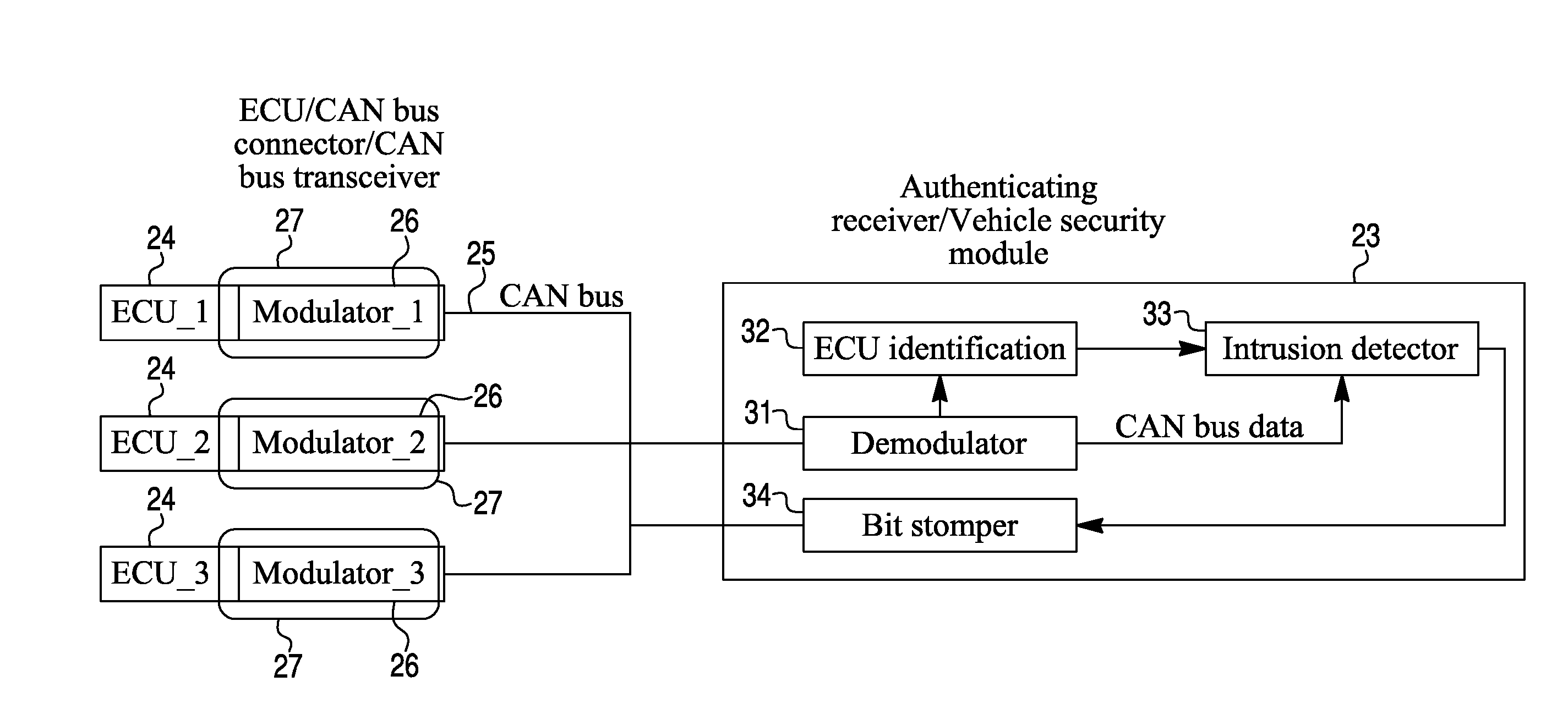
[0038] Second, one authenticating receiver 23 may be employed per bus 25. Receiver 23 may contain electronics to detect the analog signal and then determine the ECU 24 bound to that analog signal. This in effect may identify the ECU 24 which is transmitting. The authenticating receiver 23 may then check the message being transmitted against the set of ECUs 24 authorized to transmit the message. If a transmitter is sending an authorized message, the authenticating receiver 23 may allow the message to be transmitted. If the transmitter is sending an unauthorized message, then authenticating receiver may block the message by corrupting the cyclic redundancy code (CRC) on the message (FIG. 9). The corrupted CRC may cause virtually all the other receivers on the bus to discard the message. The result may be that only messages that are sent from authorized ECUs 24 are accepted (e.g., processed) by receiving ECUs. The ECU source authentication system is shown in FIG. 3a. A simplified version of applying a unique signal to a message from an ECU n 24 by a dedicated modulator n 26 to CAN bus 25 is shown in a diagram of FIG. 3b.
[0039] Each ECU 24 on a bus 25 which is to be authenticated may have a modulator 26 associated with its CAN bus transceiver 27. This modulator 26 may apply an analog signal to the messages sent by an ECU 24. The analog signal may be unique to the ECU 24 identifier. Thus, ECU_1 messages may be tagged with an analog signal 1. ECU_2 messages may be tagged with an analog signal 2, and so on. ECUs 24 may apply a similar analog signal (e.g., at the same frequency) but at different times. For example, ECU_1 may apply the analog signal to bits 0-3 of the messages while ECU_2 applies the same analog signal to bits 4-7 of the message. These ECUs 24 may apply the standard CRC check as specified by the CAN bus 25 protocol.
[0040] The number of possible schemes (frequency, timing, modulation, binary encoding of an ID number, and so forth) for tagging CAN bus 25 messages may be nearly unlimited. No attempt is necessarily made here to enumerate all the possible combinations. The parameters that a designer should work with may include the following items. One may be frequency. The frequency of the signal may be varied such that a low frequency represents one tag and a higher frequency represents a second tag. Another may be timing. The timing of when the modulation is applied, may be varied. The modulation may start at different bit times within a message, and its duration may also vary. It is also possible to support various patterns such as, for example, modulation on for 3 bits, off for 4 bits and then on for 5 bits. A binary number may be encoded using a modulation scheme such as frequency shift keying, on/off keying or other encoding techniques.
[0041] Another parameter may be waveform. There are many waveforms which may be used for signaling in addition to a simple sine wave. For example, quadrature phase shift keying may be used to encode many transmitter IDs.
[0042] Another parameter may be amplitude. The amplitude of the signal may be varied. While amplitude variation is possible, it may introduce potential issues of noise, attenuation and other physical issues which could make signal detection more complex.
[0043] Each ECU 24 on bus 25, which does not necessarily require source authentication, may have a legacy transceiver without a modulator. Thus, authenticating ECUs and non-authenticating ECUs may be mixed on the same bus and interoperate. There may be a risk that a non-authenticating ECU could transmit an unauthorized message. However, the reality of vehicle production may require that ECUs without authentication capability be accommodated until the supply chain is switched over to authenticating ECUs. The non-authenticating ECU may still apply a standard CRC check as specified by CAN bus protocol. The authenticating receiver should contain a list of messages (arbitration IDs) which require authentication. If a non-authenticating ECU attempts to forge a message which requires authentication, the authenticating receiver may detect the missing analog signature and mark the message as unauthorized by stomping on the CRC, thus causing all ECUs 24 to reject the non-authenticated message. Therefore, the non-authenticating ECU may still discard messages which the authenticating receiver marks as unauthorized by corrupting the CRC.
[0044] For each CAN bus 25, there may be an authenticating receiver 23 (sometimes called a vehicle security module). Vehicle manufacturers may place multiple authenticating receivers 23 in a gateway module which connects multiple CAN busses 25. The authenticating receiver 23 may perform the following functions.
[0045] One may be demodulation. The CAN bus signal may be received and demodulated. A demodulator 31 may convert the analog signal on the CAN message to an input to the ECU identification 32. This input may indicate one or more characteristics of frequency, timing, and modulation type, or all three of the characteristics. Depending upon the analog scheme chosen for the implementation, demodulator 31 may also directly output the number of the transmitting ECUs 24.
[0046] Another function may be ECU identification 32. For generality, one may assume that the demodulator 31 outputs characteristics of the demodulated signal that are used by the ECU identification 32 function to determine the ECU identifier. The ECU identifier may be able to output an identity of the transmitting ECU 24 in digital form (e.g., 1, 2, and so on).
[0047] Another function may be intrusion detector 33. The intrusion detector 33 function may receive two inputs. The function may accept the ECU identifier from the ECU identification 32 function. It also may accept CAN bus 25 data from the transceiver 27 (typically co-located with demodulator 26). Intrusion detector 33 may use the message identifier (i.e., an arbitration ID) on the message together with the ECU identifier 32 to determine if the message is from an ECU 24 which is authorized to send the message. This determination may be implemented from a lookup table. If the intrusion detection 33 function determines that the transmitting ECU 24 is authorized to transmit the message, then intrusion detection does not necessarily invoke a function of a bit stomper 34. However, if the intrusion detector 33 determines that the transmitting ECU 24 is not authorized to send the message (based upon the message ID), then bit stomper 34 may be activated. Bit stomper 34 may actively drive the signal on the CAN bus 25 to force a CRC error. The CRC error in turn may cause all ECUs 24 on bus 25 to reject the message.
[0048] A result of the present system is that an ECU 24 may be prevented from transmitting an unauthorized message that is accepted by other ECUs on bus 25. CAN bus 25 signaling may be described in a context of the modulation scheme which adds an analog component.
[0049] CAN bus 25 may be a two-wire system as shown in FIG. 4. The two lines 41 and 42 of bus 25 may carry CAN high (H) and CAN low (L) signals, respectively. Bus 25 may be terminated at both ends with 120 ohms across lines 41 and 42. CAN transceivers 27 may be connected across lines 41 and 42 with stubs 43 and 44, respectively.
[0050] Each of differential signals or voltages 45 and 46 on CAN bus 25 may be a 5V or 3.3 V signal, as shown in FIGS. 5a and 5b, respectively. The signals CANL (CAN-L) and CANH (CAN-H) may have recessive logic H, dominant logic L, recessive logic H, and so on, along a time axis (t) versus typical bias voltage (V).
[0051] FIG. 6 is a diagram of a raw CAN bus signal waveform 47 without modulation. Like that of FIGS. 5a and 5b, the recessive logic H and dominant logic L portions of the waveform are revealed.
[0052] A representation of the modulated CAN signal (i.e., with an analog signature 49 added) is shown in a waveform 48 in FIG. 7. The modulation does not necessarily have to be applied to every bit. The timing scheme may apply modulation 49 only at specific times. Waveform 48 shows modulation 49 occurring within the dominant portion of the signal. Modulation may also be applied during the recessive portion so long as it is within the noise margins. The modulated signal may still meet the CAN bus signal specifications. One or more modulation types may be selected from a group comprising frequency shift keying (FSK), amplitude shift keying, (ASK) on/off keying (OOK), phase shift keying (PSK), quadrature phase shift keying (QPSK), quadrature amplitude modulation (QAM) and continuous phase modulation (CPM).
[0053] The modulator function may be applied in any of four locations. First, the modulator function may be integrated in a CAN bus connector. A modulator chip may be embedded into the CAN bus connector connecting a legacy (i.e., with no modulator capability) ECU to the CAN bus.
[0054] Second, the modulator function may be integrated between the CAN wiring harness and the ECU. An additional "modulating connector" may be spliced between the existing CAN connector and the legacy ECU.
[0055] Third, the modulator function may be integrated as a chip on the ECU PCB. The modulator function may be implemented on a printed circuit board (PCB) of the ECU outside of the legacy transceiver.
[0056] Fourth, the modulator function may be integrated into the CAN transceiver. The modulation function may be integrated into the transceiver chip itself. FIG. 8 is a diagram of a modulation scheme integrated within a transceiver 50. The modulation scheme (i.e., the analog signature) may be applicable to both a traditional CAN as well as a newer CAN with a flexible data rate (CAN-FD).
[0057] Line 51 may be for a CAN transmit data input, also called TXD, a driver input. Line 52 may be a CAN mode select, low power versus high speed. Line 51 may go to an input of an amp 53 that may provide inverted and non-inverted outputs, first and second outputs, respectively, to a gate of a P-channel FET 54 and to a gate of an N-channel FET 55. FET 54 may have a source connected to a cathode of a Zener diode 56 and a drain connected to a modulator circuit 58. FET 55 may have a drain connected to a cathode of a Zener diode 57 and a source connected to a ground (GND) terminal. An anode of diode 56 may be connected to a voltage supply (Vcc). An anode of diode 57 may be connected to modulator 58. An output 61 from modulator 58 may be a CANH, a high level CAN bus line. An output 62 from modulator 58 may be a CANL, a low level CAN bus line. Outputs 61 and 62 may be connected to a Schmitt trigger 63. An output 64 from trigger 63 may be CAN received data, also called RXD. Input 52 may go to a slope control and mode logic circuit 65, which may have an output to amp 53 and an output to trigger 63.
[0058] As to FIG. 3, a simple modulator may be placed in line between an ECU and CAN bus 25. The modulator may deliberately add a signature to a native electrical signal from the ECU. There may be modulator implementation options. It may be part of the wiring harness. It may be a dedicated IC placed after a transceiver 27 or be part of a CAN bus transceiver. Implementation may incorporate programmability at the factory or the field, or not be programmable.
[0059] FIG. 9 is a diagram of an electronic control unit fingerprint applied to a Controller Area Network message.
[0060] The portions of an ECU fingerprint may incorporate one bit for a Start of Frame (SF) 81, 11 to 29 bits for a message identifier 82, 6 bits for control 83, up to 64 bits for data 84, 16 bits for CRC 85, 2 bits for ACK 86 and 7 bits for End of Frame (EF) 87. The ECU identification may be applied during the transmission of control bits and data bits. The bit stomping could be applied during the transmission of the control, data or CRC bits.
[0061] FIG. 10 is a diagram of a CAN bus signal 91 on a scope. Signal 91 may have a differential voltage of a dominant logic L signal at levels 92 and 93, for example. The waveform may reveal ringing 94, rise time 95 amplitude 96 and bit time variance 97 of signal 91.
[0062] FIG. 11, like FIGS. 5a, 5b, 6, 7, and 11, shows a logic signal 101 having a recessive logic "1" signal and dominant logic "0" signal. Corresponding to logic signal 101 are CAN-H and CAN-L signals 102 that have a magnitude of 2.5 volts each or a differential magnitude of about zero volts at the recessive logic H signal. The CAN-H and CAN-L signals 102 have magnitudes of 3.75 volts and 1.25 volts, respectively, and together have a differential magnitude of about 2.5 volts at the dominant logic L signal.
[0063] FIG. 12 shows the block diagram of a demonstration system. The purpose of the system may be to demonstrate that the RF (analog) identification signals and native CAN signals can coexist on the same physical channel (twisted pair). The timing of the transmission, decoding by a vehicle security module and enforcement decision may all be performed within the timing constraints of an operational CAN bus. The system may typically integrate the RF transmission and receiver functions in CAN transceivers in order to reduce cost size and power requirements.
[0064] Requirements for classic CAN device authentication transmitter may be noted. The authenticating transmitter may start transmitting an FSK modulated carrier when the device transmitter begins a transmission. Due to delays in responding to a start of transmission indication, this should occur <1-2 uS after the CAN transmission starts.
[0065] The message may consist of a packet containing, at a minimum, a sync header and ID number for the CAN ECU. The ID number may be the base CAN ID (11 bit ID) in systems where multiple virtual devices exist in a single ECU.
[0066] The data rate for the authentication transmission should be sufficiently fast such that the authentication message is complete well before the shortest CAN message can be transmitted. For a standard rate CAN bus {1 MHz), this may be before the end of the 36th bit of the message (assuming a single 8 bit data field), or 36 microseconds (uS). The design must allow sufficient time for the authenticating receiver to process the message and act upon it.
[0067] The authenticating receiver may use a microcontroller or hardware based logic (e.g., a gate array) to accomplish the required calculations within the required time.
[0068] Needs for a CAN device authentication receiver may be noted. The authenticating receiver of a vehicle security module (VSM) may listen continuously for transmissions containing analog authenticating transmissions. When a CAN transmission is detected, the message ID may be decoded and compared to the analog ID received, if any. The CAN message ID may be compared against the analog ID to see what types of commands this ECU is allowed to transmit. If this is a valid message for this particular ECU to transmit (i.e., a correct analog ID, allowed command type for this particular ECU), no action is necessarily taken.
[0069] If the message from the ECU is not accompanied by a validating analog (RF) transmission with the correct ID number and this ECU is required to be accompanied by a validating analog (RF) transmission, the authenticating receiver should short the bus (assert a dominant 1 bit) for more than 6 bit times before releasing the bus. This should invalidate the bus traffic as this is not necessarily a valid message for this ECU, real or spoofed, to send.
[0070] If the message from the ECU is accompanied by a validating analog (RF) transmission with the correct ID number, the authenticating receiver should decode the command field of the message and determine if this device is allowed to transmit this command. If it is not allowed to transmit this command, then the authenticating receiver should short the bus (assert a dominant 1 bit) for more than 6 bit times before releasing the bus. This may invalidate the bus traffic as this is not necessarily a valid message for this ECU, real or spoofed, to send.
[0071] If this message is from an ECU that is not required to have an accompanying validating RF transmission, then the authenticating receiver may still need to decode the message and determine if this is a valid command for this ECU to send. If it is not, then the VSM should short the bus (assert a dominant 1 bit) for more than 6 bit times before releasing the bus. This may invalidate the bus traffic as this is not necessarily a valid message for this ECU, real or spoofed, to send.
[0072] It may be noted that it is not necessarily needed for all ECU's to have an authenticating analog (FSK) transmission, but all messages from all ECU's should be checked against a list of valid commands for any particular ECU to send.
[0073] An analysis for the system may include looking at the timing budget for the sender to apply the electronic control unit (ECU) identifier and for the receiver (policy enforcement) to decode the signal and make a decision whether or not to stomp on the CRC.
[0074] FIG. 12 may also be regarded as a diagram of an instance of a present system 201, which may have an ECU module 202 and a vehicle security module 203. In module 202, an ECU (#1) 204, for example, may have an output (Tx.d) 205 connected to a transceiver 206 and an RF transmitter 207. ECU 204 may have another output (Tx/Rx) 208 connected to transceiver 206. An output (Rx.d) 209 from transceiver 206 may go to ECU 204. Transceiver 206 may be a Silicon Labs SLWSTK6221A 434 MHz dev kit. Transceiver 206 may be instead a circuit capable of applying an analog ID signal. Transceiver 206 may be connected to lines 211 and 212 of a bus 213. RF transmitter 207 may have lines 214 and 215 connected to a first winding of a transformer 218. A second winding of transformer 218 may have lines 221 and 222 connected to first terminals of capacitors 216 and 217, respectively. A nominal value of each capacitor may be 10 pf, but it may be another value as desired. Second terminals of capacitors 216 and 217 may be connected to lines 211 and 212, respectively, of bus 213. Transformer 218 may be a Minicircuits ADT2-1T-1P+ 1:2 transformer.
[0075] Vehicle security module 203 may have an RF receiver/decoder 225. RF receiver/decoder 225 may be a TI CC1200 dev kit or other model as desired. An output line (Tx.d) 226 and line (Tx/Rx) 227 of RF receiver/decoder 225 may go to a transceiver 229. An output line (Rx.d) 228 may go to receiver/decoder 225. Output lines 231 and 232 may go from receiver/decoder 225 to a first winding of a transformer 233. A model of transformer 233 may be like that of transformer 218. Lines 234 and 235 may go from a second winding of transformer 233 to first terminals of capacitors 236 and 237, respectively. The second terminals of capacitors 336 and 337 may be connected to lines 211 and 212, respectively, of bus 213.
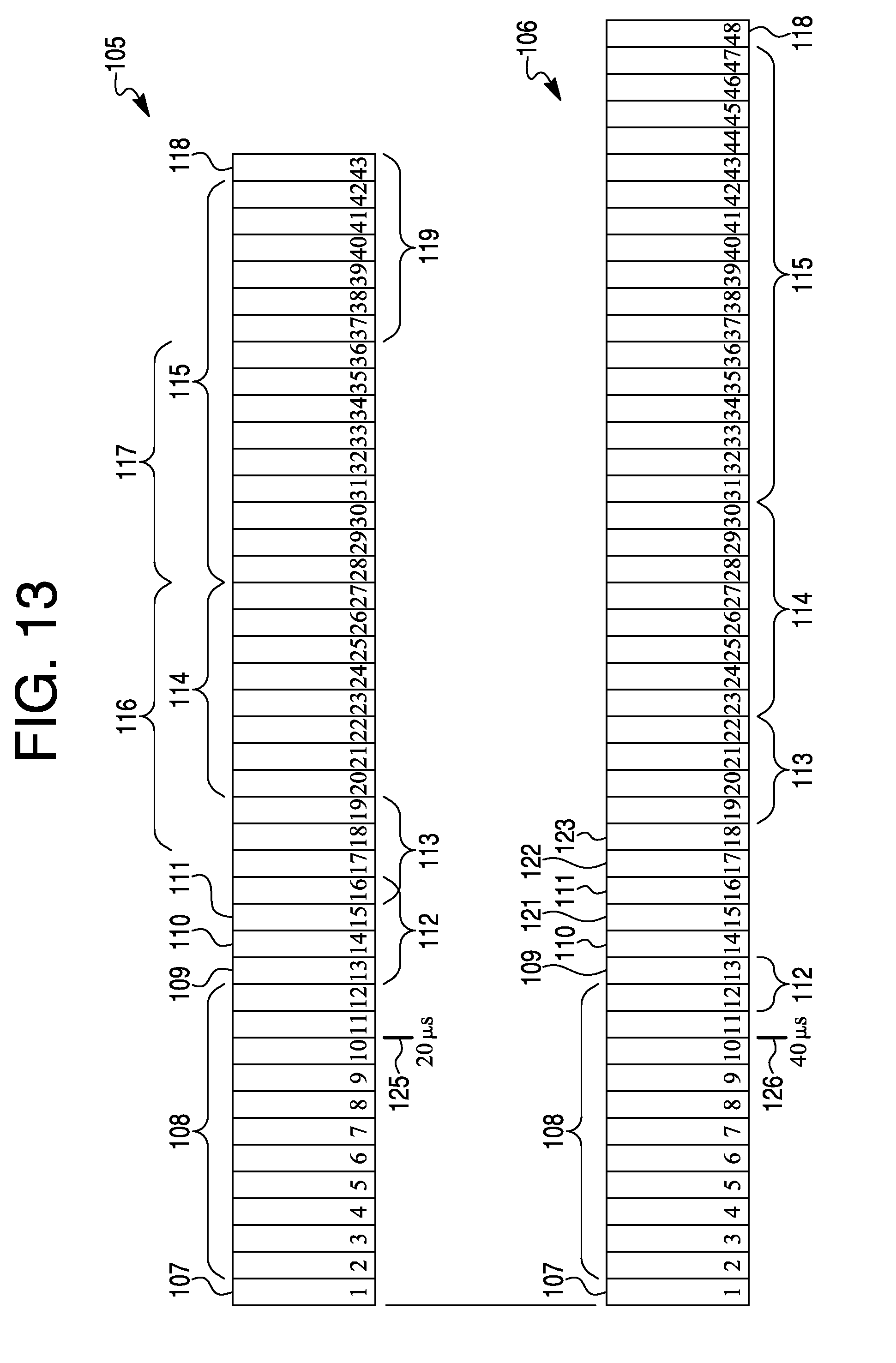
[0076] FIG. 13 is a diagram that shows an additional analysis of the transmission of the ECU identification. It may reveal a message packet 105. Bit 107 may be a start of a frame. Bits 102-112 may represent an arbitration field 108. Bit 13 may represent a remote transmitter request 109. Bit 14 may represent an ID extension bit 110. Bit 15 may represent a reserved bit 111. Bits 13-16 may represent an 8 uS (microsecond) Tx start-up 112. Bits 16-19 may represent data length 113. Bits 20-27 represent 8 bit data 114. Bits 28-42 may represent a 15 bit CRC 115. Bits 17-27 may represent a 22 uS transmission 116. Bits 28-36 may represent an 18 uS stomp decision 117. Bit 43 may represent a CRC delimiter 118. Message packet 105 may be run on a CAN bus at 500 kbps.
[0077] A message packet 106 may run on a CAN FD at 250 bkbps, which is one-half the speed that packet 105 is run. Bits 15, 17 and 18 may represent flexible data 121, bit rate switch 122 and error status indicator, respectively. Data length 113 may be represented by bits 19-22. Eight-bit data length 114 may be represented by bits 23-30. A seventeen bit CRC 115 may be represented by bits 31-47. CRC delimiter 118 may be represented by bit 48.
[0078] A 20 uS mark 125 may occur at bit 10 in packet 105. That may be a 40 uS mark 126 at bit 10 in packet 106. Each bit may be 2 uS in packet 105 and 4 uS in packet 106.
[0079] Bus Tx startup 112 may be during bits 12 and 13 in packet 106. An 88 uS transmission 116 may be during bits 14-36. A 20 uS stomp decision 117 may be during bits 37-41. Seven bits 119 may remain after stomp decision 117.
[0080] Requirements for a CAN authentication transmitter may be noted. The authenticating transmitter should decode the ECU 10 field while monitoring both the transmitter enable line and transmitter data line on the ECU in order to determine if the ECU to which the ID transmitter is attached has actually taken control of the bus. This may be done by decoding the transmitted address. Normally, a non-bit-stuffed ECU 10 field may be 11 bits in length. Because CAN data is limited to a run length of 5 bits, maximum, this could expand the 10 field to as long as 13 bits if there are two sequences of run length limits in the 10 field. The authenticating RF transmitter should monitor the transmitted 10 field and determine if bit-stuffing has occurred in order to properly determine when the end of the 10 field occurs. If the transmitter is still active after the last bit of the bit-stuffed ID field, then the device may have taken control of the bus and the authenticating transmitter may be engaged to send the RF ID data to the authenticating receiver (VSM).
[0081] FIG. 14 is a diagram of a packet 130. Some differences may be apparent when compared to packet 106. Message packet 130 may be run on a CAN at 125 kbps. An 8 uS Tx startup 112 may occur during bit 12, which is the remote Tx request. Transmission time available may occur from bit 13 to about one-fourth way through bit 34. A stomp decision 117 may run from about one-fourth way through bit 34 up to bit 37. Seven bits 119 may remain after bit 36 through bit 43. There may be an 80 uS preamble with 40 symbols beginning at bit 13. There may be a 4 byte sync of 32 uS beginning at bit 22. There also may be an 8 uS data at bit 26 and a 16 uS CRC at bits 29 and 30. There may be a 136 uS verification transmission length beginning at bit 12. A 48 uS stomp decision 117 may begin during bit 31.
[0082] FIG. 15 may be a diagram of a timing analysis that shows that the system can perform the needed transmission and decoding in order to prevent a successful transmission of messages from unauthorized sources. RF startup time for CC1200 transition may be from Rx to Tx state (43 uS). Reducing the preamble from 40 to 20 symbols may increase the stomp decision time to 61 uS. This should be more than adequate, even with allowing additional time to initialize the Tx and decode the message in the Rx. One may note that the RF symbol rate is 500 ksps due to using 4(G) FSK transmission to achieve 1 Mbps throughput.
[0083] For proof of the present system, the RF components may be implemented outside of the CAN transceiver chip. The proof of concept design for the transmitting ECU is shown herein.
[0084] FIG. 15 has the diagram of a packet 135 running on a 125 kbps CAN. After bit 11, there may be a 43 uS Tx startup. The pattern of packet 135 may be the same as packet 130. There may be a 200 uS total time available after bit 11. A 40 uS preamble with 20 symbols may start during bit 17. There may be a 4 byte sync of 32 uS beginning during bit 21. Bus data may occur for about one bit after the sync. A 16 uS CRC may begin during bit 26. A 61 uS stomp decision may occur after the CRC. Seven bits may remain after the stomp decision. A 96 uS verification transmission length may begin during bit 17.
[0085] Packet 135 may begin with a start of frame bit 107. An arbitration field 108 may follow bit 107. A Tx start up 112 may run from field 108 to a start of a 20 symbol preamble 136. Sync bits 137 may follow preamble 136 up to data 138. CRC 139 may go from data 138 to a stomp decision 117. If there is no stomp decision, then CRC 139 may continue, including 7 bits remaining 119, to CRC delimiter 118. Bits following Tx start up 112 up to stomp decision 117 may be a verification transmission length 141. Total time available may run from a beginning of Tx start up 112 through stomp decision 117.
[0086] FIG. 16 is a diagram showing a transmit portion of the system. A chip CC1200 may ideally wake on Tx/Rx->Tx and watch the Tx.d and Rx.d data lines to determine if ECU #1 has: 1) Started to transmit; 2) Captured the bus by comparing the transmitted ID to the received ID in that a mismatch indicates that the bus was not captured; and 3) Finished transmitting the ECU ID field so that a radio can start sending the ECU ID.
[0087] A transmission may be initiated by pressing the button attached to the ECU. An LED may light up to indicate that a bus transaction has started. When the ECU has captured the bus and has finished sending its ID, the transceiver may switch from receive to transmit and send out a preamble, sync sequence, the ECU ID#, and the message CRC. This may identify the device originating the transmission and the validity of the transmission may be determined by the vehicle security module.
[0088] For our demonstration purposes, a CC1200 need only delay after the start of the transmission because there will be necessarily no devices contending for the bus. A receive function of the RF transceiver can be used only to hold the transmit frequency. This appears necessary to speed up the time from transmitter initiation to actual RF output.
[0089] FIG. 16 may also be regarded as a diagram of a transmitting portion 140 of a version of the present system. A freescale/NXP transceiver 142 that may incorporate an ECU 143 and a transceiver 144. ECU 143 may have a transmit button 145 and an LED indicator 146. Transmitting portion 140 may further incorporate a CC 1200 RF transceiver 147. Transceiver 147 may be instead one of several other available models. ECU 143 may have an output (Tx.d) 148 to transceiver 144 and transceiver 147, and an output (Tx/Rx) 149 to transceiver 144 and transceiver 147. Transceiver 144 may have an output (Rx.d) 151 to ECU 143 and transceiver 147. Transceiver 144 may have connections to lines 152 and 153 of a bus 154. Transceiver 147 may have connections to lines 155 and 156 to a first winding of a Minicircuits ADT2-1T-1P+ 1:2 transformer 157. Transformer 157 may be instead one of several other available models. A second winding of transformer 157 may be connected to lines 158 and 159, which in turn may be connected to first terminals of capacitors 161 and 162, respectively. The second terminals of capacitors 161 and 162 may be connected to lines 152 and 153, respectively, of bus 154. Nominal values of capacitors 161 and 162 may be 10 pf, or other values as desired.
[0090] The receiver (vehicle security module which may perform enforcement) is shown in FIG. 17. The RF receiver components may typically be integrated in the CAN bus transceiver. CC1200 may be virtually always in a receive mode listening for an RF signal on the bus. When the VSM detects bus activity, the microcontroller may decode the bus ID field and wait for a message from the CC1200 indicating that it received data. The microcontroller may retrieve the data and compare the bus address with the ECU ID. The RF ID and the CAN ID may be compared to a table of allowed RF ID and CAN ID pairs. If the table indicates they are allowed to communicate, nothing appears to happen and the microcontroller may go back to sleep. If the table indicates that this is not an allowed transaction, the microcontroller may turn on the CAN transceiver and send out either a 7 byte sequence of solid zeros or a hash of random data to jam the bus and invalidate the transmission.
[0091] If no RF appears in the receiver before 200 uS has elapsed, the microcontroller may turn on the CAN transceiver and send out either a 7 byte sequence of solid zeros or a hash of random data to jam the bus and invalidate the transmission. After the 7 byte quash/jam sequence is sent, the VSM may go back to sleep. A red LED may indicates that the VSM has quashed a transmission. A green LED may indicate that an authenticated transmission has occurred. A red LED may indicate that an invalid transmission was detected. The LED indication may be for illustrative purposes.
[0092] FIG. 17 may also be regarded as a diagram of a receiving portion 150 of a version of the present system. Portion 150 may be regarded as a vehicle security module. A microcontroller 164 may have an output (Tx.d) 166 to a transceiver 165 and also an output (Tx/Rx) 167 to transceiver 165. Transceiver 165 may have an output (Rx.d) 168 to microcontroller 164. Microcontroller 164 may be a Cortex M4 @ 200 MHz or a Cortex A9 @ 1 GHz. Microcontroller 164 may be one of several other available models.
[0093] Microcontroller 164 may have an LED indicator 169. Lines 171 and 172 may connect microcontroller 164 to a CC1200 RF transceiver 174. Transceiver 165 may be connected to lines 152 and 153 of bus 154. Transceiver 174 may have lines 175 and 176 connected to a first winding of a Minicircuits ADT2-1T-1P+ 1:2 transformer 177. Transformer 177 may be instead one of several other available models. A second winding of transformer 177 may be connected to lines 178 and 179, which in turn may be connected to first terminals of capacitors 181 and 182, respectively. The second terminals of capacitors 181 and 182 may be connected to lines 152 and 153, respectively, of bus 154. Nominal values of capacitors 181 and 182 may be 10 pf, or other values as desired.
[0094] To recap, an authentication system may incorporate a bus, a transmitter connected to the bus, and a receiver connected to the bus. A physical layer signal may be applied by the transmitter to a message on the bus for authenticating the transmitter. The physical layer signal may incorporate an identifier (ID) of the transmitter. The receiver may receive the message and decode the physical layer signal on the message. A decoding of the physical layer signal on the message may reveal the ID of the transmitter sending the message. The receiver may look up the ID on a list of IDs corresponding to transmitters approved to send the message, to determine whether the ID of the transmitter sending the message matches an ID on the list. If the ID of the transmitter matches an ID on the list, then the transmitter may be authenticated and authorized to send the message.
[0095] If the transmitter is authenticated, the message sent by the transmitter that is received by the receiver may be processed by the receiver. If the transmitter cannot be authenticated, then the message sent by the transmitter that is received by the receiver may be blocked and not processed by the receiver.
[0096] A message having a physical layer signal, may be received by the receiver without interference to an ability of the receiver to receive and decode another message that is a normal signal digitized data message per a communications standard.
[0097] The bus may be a controller area network (CAN). The message may be a CAN message. The CAN message may have a dominant portion and a recessive portion. The physical layer signal may be applied to a dominant portion, a recessive portion, or both a dominant and a recessive portion of the CAN message. Or one or more media may be selected from a group incorporating wired media, optical media, radio frequency media, that may be used singularly or in combination for the system.
[0098] The bus may incorporate one or more additional receivers that detect the blocking of the message by the receiver that checks the ID decoded from the physical layer signal on the message from the transmitter and determines that the ID of the transmitter does not match an ID on a list of IDs corresponding to transmitters approved to send the message, and in turn blocks the message.
[0099] Only one receiver on the bus needs to receive the message and decode the physical layer signal applied to the message. The system only needs one authenticating receiver because the bit stomping function, together with the CRC allows the authenticating receiver to block other receivers from receiving the message. However, the system may have one or more receivers on the bus which can decode the physical layer signal applied to the message.
[0100] The bit stomping function is not necessarily the only way to block an unauthorized message. Having one authenticating receiver which performs bit stomping (invalidating the CRC) may be a cost effective way of implementing the system because one authenticating receiver can block the unauthorized message from all receivers. A system could have two or more authenticating receivers which decode the authentication signal and simply prevent the local node from processing the message, i.e., they do not necessarily do bit stomping to prevent other nodes from receiving the message.
[0101] If a transmitter is authorized to transmit a message, the receiver may allow the message to be processed without interfering with the message.
[0102] If the transmitter is not authorized to transmit a message, according to an ID check, then the receiver may block a processing of the message by asserting a signal on the bus that causes a cyclic redundancy code (CRC) associated with the message to be corrupted.
[0103] One or more nodes on the bus having receivers may detect corruption of the CRC associated with the message and thus may not process the message.
[0104] Two or more receivers on the bus may receive and decode a physical layer signal on the message to obtain an ID of the transmitter of the message and determine whether the ID matches an ID on a list of IDs of transmitters authorized to send the message.
[0105] If the any one of the two or more receivers determines that the transmitter is authorized to transmit the message, then the any one of the two or more receivers may allow the message to be processed by a local processor. If the any one of the two or more receivers determines that the entity was not authorized to transmit the message, then the any one of the two or more receivers may block a processing of the message by the local processor.
[0106] The transmitter may apply a modulated signal to the physical layer signal to code an ID for authentication of the transmitter. One or more modulation types may be selected from a group having frequency shift keying (FSK), amplitude shift keying, (ASK) on/off keying (OOK), phase shift keying (PSK), quadrature phase shift keying (QPSK), quadrature amplitude modulation (QAM) and continuous phase modulation (CPM).
[0107] The bus may incorporate one of the following receiver and transmitter combinations of components: one or more authenticating receivers, and one or more authenticating transmitters; one or more authenticating receivers, one or more authenticating transmitters, and one or more non-authenticating receivers; one or more authenticating receivers, one or more authenticating transmitters, and one or more non-authenticating transmitters; one or more authenticating receivers, one or more authenticating transmitters, one or more non-authenticating receivers, and one or more mon-authenticating transmitters; only one authenticating receiver and only one authenticating transmitter; only one authenticating receiver, only one authenticating transmitter, and one or more non-authenticating receivers; only one authenticating receiver, only one authenticating transmitter, and one or more non-authenticating transmitters; or only one authenticating receiver, only one authenticating transmitter, one or more non-authenticating receivers, and one or more non-authenticating transmitters.
[0108] A receiver and transmitter combination that has components that perform authenticating functions and non-authenticating functions may interoperate in accordance with a security policy applied by one or more authenticating components.
[0109] An authentication approach may incorporate applying a physical layer authentication signal to a message to be sent by a transmitter on a bus; decoding an identifier (ID) from the physical layer authentication signal on the message to be received by a receiver on the bus; and looking up the ID on a list of IDs corresponding to transmitters approved to send the message, to determine whether the ID decoded from the physical layer authentication signal matches an ID on the list. If the ID matches an ID on the list, then the message on the bus may be authorized. If the ID matches no ID on the list, then the message on the bus may be unauthorized.
[0110] The approach may further incorporate accepting and processing the message on the bus if the message is authorized, and blocking the message on the bus if the message on the bus is unauthorized.
[0111] Only one receiver on the bus may receive the message and decode the physical layer authentication signal applied to the message.
[0112] A mechanism for authenticating transmissions, may incorporate a transmitting entity, a receiving entity, and a bus connected to the transmitting entity and the receiving entity. A physical layer signal may be applied by the transmitting entity to a message on the bus to authenticate the transmitting entity. The physical layer signal may incorporate an identifier (ID) of the transmitting entity. The receiving entity may receive the message and decode the physical layer signal on the message. A decoding of the physical layer signal on the message may reveal the ID of the transmitting entity sending the message. The receiving entity may look up the ID on a list of IDs corresponding to transmitting entities approved to send the message, to determine whether the ID of the transmitting entity sending the message matches an ID on the list. If the ID of the transmitting entity matches an ID on the list, then the transmitting entity may be authenticated. If the ID of the transmitting entity does not match an ID on the list, then the transmitting entity may be not authenticated.
[0113] If the transmitting entity is authenticated, the message sent by the transmitting entity that is received by the receiving entity may be processed by the receiving entity. If the transmitting entity is not authenticated, then the message sent by the transmitting entity that is received by the receiving entity may be blocked and not processed by the receiving entity.
[0114] A message having a physical layer signal, may be received by the receiving entity without interference to an ability of the receiving entity to receive and decode another message that is a normal signal digitized data message per a communications standard.
[0115] Any publication or patent document noted herein is hereby incorporated by reference to the same extent as if each publication or patent document was specifically and individually indicated to be incorporated by reference.
[0116] In the present specification, some of the matter may be of a hypothetical or prophetic nature although stated in another manner or tense.
[0117] Although the present system and/or approach has been described with respect to at least one illustrative example, many variations and modifications will become apparent to those skilled in the art upon reading the specification. It is therefore the intention that the appended claims be interpreted as broadly as possible in view of the related art to include all such variations and modifications.
* * * * *
D00000
D00001
D00002
D00003
D00004
D00005
D00006
D00007
D00008
D00009
D00010
D00011
D00012

D00013
D00014

D00015

D00016

XML
uspto.report is an independent third-party trademark research tool that is not affiliated, endorsed, or sponsored by the United States Patent and Trademark Office (USPTO) or any other governmental organization. The information provided by uspto.report is based on publicly available data at the time of writing and is intended for informational purposes only.
While we strive to provide accurate and up-to-date information, we do not guarantee the accuracy, completeness, reliability, or suitability of the information displayed on this site. The use of this site is at your own risk. Any reliance you place on such information is therefore strictly at your own risk.
All official trademark data, including owner information, should be verified by visiting the official USPTO website at www.uspto.gov. This site is not intended to replace professional legal advice and should not be used as a substitute for consulting with a legal professional who is knowledgeable about trademark law.