Cassette Holder Assembly For A Substrate Cassette And Holding Member For Use In Such Assembly
den Hartog Besselink; Edwin ; et al.
U.S. patent application number 16/208062 was filed with the patent office on 2019-04-18 for cassette holder assembly for a substrate cassette and holding member for use in such assembly. The applicant listed for this patent is ASM IP Holding B.V.. Invention is credited to Edwin den Hartog Besselink, Marco Dirkmaat, Adriaan Garssen.
| Application Number | 20190115237 16/208062 |
| Document ID | / |
| Family ID | 65275447 |
| Filed Date | 2019-04-18 |


| United States Patent Application | 20190115237 |
| Kind Code | A1 |
| den Hartog Besselink; Edwin ; et al. | April 18, 2019 |
CASSETTE HOLDER ASSEMBLY FOR A SUBSTRATE CASSETTE AND HOLDING MEMBER FOR USE IN SUCH ASSEMBLY
Abstract
The invention relates to a cassette holder assembly for holding a cassette for storing at least one semiconductor material substrate in an interior space accessible from a front end of the cassette. The cassette holder assembly may have a base plate for receiving the cassette. Two holding members supported by the base plate may be positioning the cassette on the plate in the assembly. The holding members may be substantially identical to each other.
| Inventors: | den Hartog Besselink; Edwin; (Amsterdam, NL) ; Garssen; Adriaan; (Doorn, NL) ; Dirkmaat; Marco; (Amersfoort, NL) | ||||||||||
| Applicant: |
|
||||||||||
|---|---|---|---|---|---|---|---|---|---|---|---|
| Family ID: | 65275447 | ||||||||||
| Appl. No.: | 16/208062 | ||||||||||
| Filed: | December 3, 2018 |
Related U.S. Patent Documents
| Application Number | Filing Date | Patent Number | ||
|---|---|---|---|---|
| 15673110 | Aug 9, 2017 | |||
| 16208062 | ||||
| Current U.S. Class: | 1/1 |
| Current CPC Class: | H01L 21/67769 20130101; H01L 21/67775 20130101; H01L 21/67379 20130101; H01L 21/67353 20130101; H01L 23/32 20130101 |
| International Class: | H01L 21/673 20060101 H01L021/673; H01L 21/677 20060101 H01L021/677 |
Claims
1. A cassette holder assembly for holding a cassette for storing at least one semiconductor material substrate in an interior space accessible from a front end of the cassette, the cassette holder assembly comprising: a base plate for receiving the cassette; and, a right and a left holding member supported by the base plate to position the cassette on the right and left respectively seen from the front; wherein the right and left holding members are substantially identical to each other, wherein each of the holding members has at least two end surface to engage with the cassette to limit a position of the cassette in the front to the back direction substantially parallel to the base plate, the at least two end surfaces comprising at least one right surface and at least one left end surface whereby the right end surface is located at the outer right of the holding member and the left end surface is located at the outer left of the holding member seen from the front.
2. The cassette holder assembly according to claim 1, wherein each of the holding members are mirror symmetrical with respect to a line through the center of the holding member from a back to the front.
3. The cassette holder assembly according to claim 1, wherein the right end surface of the right holding member and the left end surface of the left holding member are arranged for engagement with the cassette.
4. The cassette holder assembly according to claim 1, wherein the right end surface of the left holding member and the left end surface of the right holding member are not arranged for engagement with the cassette.
5. The cassette holder assembly according to claim 1, wherein each of the holding members has at least four end surfaces to engage with the cassette to limit a position of the cassette in a front to back direction substantially parallel to the base plate, a small cassette end surface and a large cassette end surface at each of the right and the left side of the cassette, whereby the small cassette end surface is located towards the front of the base plate with respect to the large cassette end surface to engage with cassettes with a relatively smaller size.
6. The cassette holder assembly according to claim 1, wherein each of the holding members has an side surface to engage an outer surface of the holding members with the cassette and limit the position of the cassette in a right to left direction substantially parallel to the base plate and substantially perpendicular to the front to back direction.
7. The cassette holder assembly according to claim 1, wherein each of the holding members comprises at least two side surfaces, comprising a right side surface and a left side surface wherein the right side surface is located at the outer right of the holding member and the left side surface is located at the outer left of the holding member seen from the front.
8. The cassette holder assembly according to claim 7, wherein the right side surface of the right holding member and the left side surface of the left holding member are arranged for engagement with an outer surface of the members and the cassette.
9. The cassette holder assembly according to claim 8, wherein the right side surface of the left holding member and the left side surface of the right holding member are not arranged for engagement with the cassette.
10. The cassette holder assembly according to claim 1, wherein each of the holding members comprise at least two side surfaces located on the exterior of the holding members, the at least two side surfaces comprising a small cassette side surface and a large cassette side surface whereby the small cassette side surface is located towards the front of the base plate with respect to the large cassette side surface to engage with cassettes with a relatively smaller size.
11. The cassette holder assembly according to claim 1, wherein both of the holding members have a side surface to engage an outer surface with the cassette and limit the position of the cassette in right to left opposite directions.
12. The cassette holder assembly according to claim 1, wherein at least one of the holding members is detachably secured to the base plate by means of a fastener through a slotted hole and wherein the slot has a direction perpendicular to a line from the front to the back.
13. The cassette holder assembly according to claim 1, wherein the holding member is provided with at least one elongated bar extending from the bottom surface of the holding member and constructed to fit in a slot provided to the base plate.
14. The cassette holder assembly according to claim 13, wherein the at least one elongated bar is smaller than the slot in a direction perpendicular to a line from the front to the back so as to allow the holding member to be adjustably secured in that direction.
15. The cassette holder assembly according to claim 13, wherein the at least one elongated bar is the same size as the slot in a direction substantially perpendicular to a line from the front to the back and is at least partially removable so as to allow the holding member to be adjustably secured in that direction.
16. A holding member to position a cassette for storing at least one semiconductor material substrate on a base plate in a cassette holder assembly, wherein the holding member has a front and a back and is substantially mirror symmetrical with respect to a line through a center of the holding member from the front to the back, wherein the holding member comprises: at least two substantially parallel end surfaces whereby one end surface is a right end surface located at the outer right of the holding member and another end surface is a left end surface located at the outer left of the holding member seen from the front; and, at least two substantially parallel side surfaces whereby one side surface is a right side surface located at the right of the holding member and another side surface is a left side surface located at the left of the holding member seen from the front.
17. The holding member according to claim 16, wherein the side surfaces are perpendicular to the end surfaces and at least one of the side surfaces intersects with at least one of the end surfaces.
18. The holding member according to claim 16, wherein the holding member is provided with a slotted hole for a fastener and wherein the slot has a direction perpendicular to a line from the front to the back of the holding member.
19. The holding member according to claim 16, wherein the holding member is provided with at least one elongated bar extending from the bottom surface of the holding member.
20. The holding member according to claim 16, wherein the holding member comprises an injection molded polymer material.
Description
CROSS-REFERENCE TO RELATED APPLICATIONS
[0001] The present application is a continuation of U.S. Non-Provisional application Ser. No. 15/673,110, filed on Aug. 9, 2017, and entitled "CASSETTE HOLDER ASSEMBLY FOR A SUBSTRATE CASSETTE AND HOLDING MEMBER FOR USE IN SUCH ASSEMBLY," the disclosure of which is incorporated herein in its entirety by reference.
FIELD
[0002] The present invention generally relates to a cassette holder assembly for holding a cassette for storing at least one semiconductor material substrate in an interior space accessible from a front end of the cassette. More particularly, the invention relates to a cassette holder assembly comprising:
[0003] a base plate for receiving the cassette; and,
[0004] at least one holding member supported by the base plate to position the cassette.
BACKGROUND
[0005] The cassette holder assembly may be employed in an apparatus used in the manufacture of discrete and integrated semiconductor products on semiconductor material substrates. To transport the substrates, cassettes may be used which may require a special cassette holder assembly. The invention may also relate to an apparatus provided with such a cassette holder assembly.
[0006] A cassette holder assembly for a substrate cassette may comprise a base plate. On the base plate a cassette for storing at least one semiconductor material substrate in an interior space accessible from the front end may be positioned. At least two holding members may be located over and supported by the base plate to position the cassette on the base plate in the correct position. For example, a right holding member may be provided on the base plate on the right seen from the front while a left holding member may be provided on the base plate on the left. The left holding member may be different than the right holding member because each holding member receives the cassette on another side.
[0007] A drawback of the holding members for the cassette holder assembly may therefore be that the members are not very versatile and that for left and right holding members different holding members may be required, which may cost extra design and fabrication time and logistic affords.
BRIEF SUMMARY OF THE INVENTION
[0008] Therefore, it is an object of the invention to provide an improved holding member for an improved cassette holder assembly.
[0009] Accordingly there is provided a cassette holder assembly for holding a cassette for storing at least one semiconductor material substrate in an interior space accessible from a front end of the cassette, the cassette holder assembly comprising:
[0010] a base plate for receiving the cassette; and
[0011] a right and a left holding member supported by the base plate to position the cassette on the right and left respectively seen from the front; wherein the right and left holding members are substantially identical to each other.
[0012] By having the right and left holding members substantially identical to each other there is no need for designing and keeping in storage special right and left holding members. This also accommodates mass production since twice as many of the same type of holding members are necessary.
[0013] According to a further embodiment there is provided a holding member to position a cassette for storing at least one semiconductor material substrate on a base plate in a cassette holder assembly wherein the holding member has a front and a back and is substantially mirror symmetrical with respect to a line through a center of the holding member from the front to the back.
[0014] By having the holding members substantially mirror symmetrical with respect to a line through a center of the holding member from the front to the back it becomes possible to use substantially identical left and right holding members. There may no longer be a need for designing and keeping in storage special right and left holding members for the cassette holder assembly. The latter also accommodated mass production since twice as many of the same type of holding members may be produced.
[0015] An apparatus for the manufacture of semiconductor products may be provided with a cassette holder assembly in accordance with the invention. Such an apparatus enables products to be manufactured in large numbers and is easy to maintain. Preferably, such an apparatus comprises detection means which signals whether the cassette for the substrates is correctly positioned.
[0016] In addition to the parts necessary for processing the semiconductor substrates, the apparatus may preferably comprise means for arranging the cassette in the holder assembly or removing the cassette from the cassette holder assembly. Substrate handlers for arranging substrates in, or removing substrates from the cassette may also be provided in the apparatus.
[0017] These and other embodiments will become readily apparent to those skilled in the art from the following detailed description of certain embodiments having reference to the attached figures, the invention not being limited to any particular embodiment(s) disclosed.
BRIEF DESCRIPTION OF THE FIGURES
[0018] It will be appreciated that elements in the figures are illustrated for simplicity and clarity and have not necessarily been drawn to scale. For example, the dimensions of some of the elements in the figures may be exaggerated relative to other elements to help improve understanding of illustrated embodiments of the present disclosure.
[0019] FIG. 1 is a front view of a cassette holder assembly in accordance with an embodiment,
[0020] FIG. 2 is a back view of a cassette holder assembly of FIG. 1 provided with a cassette with substrates having a relatively small size of 150 mm,
[0021] FIG. 3 is a back view of a cassette holder assembly of FIG. 1 provided with a cassette with substrates having a relatively large size of 200 mm, and
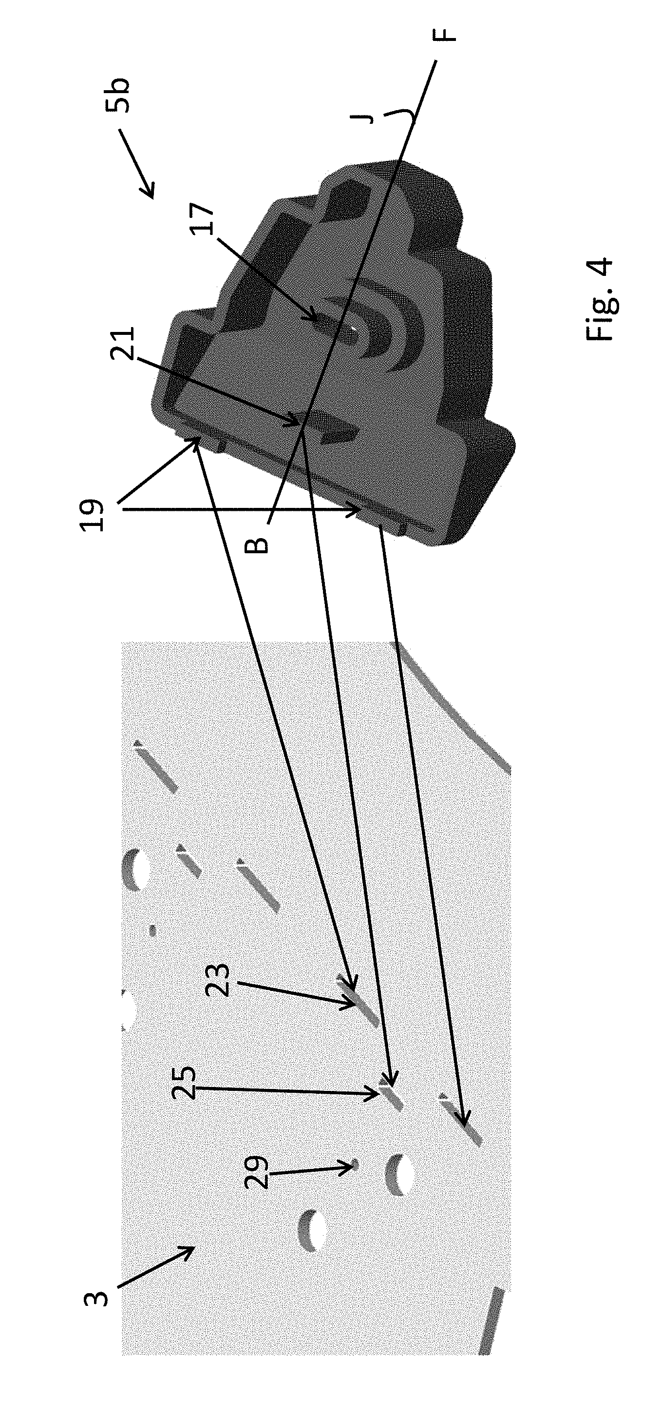
[0022] FIG. 4 is a top perspective view on a base plate for receiving the cassette and a bottom perspective view on a right holding member before mounting on the base plate.
[0023] The figures are not drawn to scale, and particularly the dimensions in the thickness direction are exaggerated for clarity. Corresponding areas bear the same reference numerals whenever possible.
DETAILED DESCRIPTION
[0024] FIG. 1 is a front view of a cassette holder assembly in accordance with an embodiment. The cassette holder assembly 1 comprises a base plate 3 for receiving a cassette (not shown) and a left holding member 5a and a right holding member 5b supported by the base plate 3 to position the cassette on the right R and left L respectively seen from the front F. The left and right holding members 5a, 5b are substantially identical to each other. Each of the holding members 5a, 5b are mirror symmetrical with respect to the line J through the center of the holding members from a back B to the front F.
[0025] An additional holding member in the form of a bar 6 may be provided on the base plate 3 to position the cassette. The bar 6 may be provided with a detector 8 to detect the presence of a cassette on the cassette holder 1.
[0026] Each of the holding members 5a, 5b may have end surfaces 7LB, 7LF, 7RB, 7RF to engage with the cassette to limit a position of the cassette in the front F to the back B direction substantially parallel to the base plate 3. Each of the holding members may have left end surfaces 7LB, 7LF and right end surfaces 7RB, 7RF. The right end surfaces 7RB, 7RF may be located at the right of the holding member 5a, 5b and the left end surfaces 7LB, 7LF may be located at the left of the holding member seen from the front F. The left end surfaces 7LB, 7LF and the right end surfaces 7RB, 7RF of the holding members 5a, 5b may be substantially parallel.
[0027] The right end surfaces 7RB, 7RF of the right holding member 5b and the left end surfaces 7LB, 7LF of the left holding member 5a may be arranged for engagement with a cassette 9 (see FIGS. 2 and 3). The right end surfaces 7RB, 7RF of the left holding member 5a and the left end surface 7LB, 7LF of the right holding member 5b may not be arranged for engagement with the cassette 9. If there is wear of the holding members on the end surfaces the position of the holding members 5a, 5b may be exchanged so that other end surfaces may be used.
[0028] Cassettes may be available in different sizes which may depend on the size of the substrates and the preferences of the fab owner in which the cassettes are used and the holding member may be constructed to be adaptable for the different sizes. Each of the holding members 5a, 5b may have at least two end surfaces defined as small cassette end surfaces 7RF, 7LF for a cassette 9 for 150 mm diameter substrates W (see FIG. 2) and large cassette end surfaces 7RB, 7LB for a cassette 9 for 200 mm diameter substrates W (see FIG. 3). The small cassette end surfaces 7RF, 7LF may be located towards the front F of the base plate 3 with respect to the large cassette end surfaces 7RB, 7LB to engage with cassettes with a relatively smaller size.
[0029] The holding members 5a, 5b may have side surfaces 11LF, 11LB, 11RF, 11RB to engage with the cassette 9 and limit the position of the cassette in a right R to left L direction substantially parallel to the base plate 3 and substantially perpendicular to the front F to back B direction. Two side surfaces defined as right side surfaces 11RF, 11RB and left side surface 11LF, 11LB may be provided. The right side surfaces 11RF, 11RB may be located at the right of the holding member seen from the front and the left side surfaces 11LF, 11LB may be located at the left of the holding member 5a, 5b seen from the front F.
[0030] The right side surfaces 11RF, 11RB of the right holding member 5b and the left side surfaces 11LF, 11LB of the left holding member 5a may be arranged for engagement with the cassette 9. The right side surface 11RF, 11RB of the left holding member 5a and the left side surface 11LF, 11FB of the right holding member 5b may be not arranged for engagement with the cassette 9.
[0031] The holding members comprise at least two side surfaces defined as small cassette side surfaces 11RF, 11LF and large cassette side surfaces 11RB, 11LB. The small cassette side surfaces 11RF, 11LF may be located towards the front F of the base plate 3 with respect to the large cassette side surfaces 11RB, 11LB to engage with cassettes 9 with a relatively smaller size (see FIG. 2). The large cassette side surfaces 11RB, 11LB may be located towards the back B of the base plate 3 with respect to the small cassette side surfaces 11RF, 11LF to engage with cassettes 9 with a relatively larger size (see FIG. 3).
[0032] Both of the holding members 5a, 5b may have a side surface to engage with the cassette and limit the position of the cassette in right R to left L opposite directions. The cassette may thereby be positioned in the left to right direction by the holding members 5a, 5b.
[0033] The holding members 5a, 5b may be detachably secured to the base plate 3 by means of a fastener e.g. a threaded fastener such as a bolt 15 through a slotted hole 17. The slotted hole 17 may have a direction perpendicular to a line from the front F to the back B for adjustment of the position of the holding member 5a, 5b on the base plate 3.
[0034] FIG. 4 is a top perspective view on a base plate 3 for receiving the cassette and a bottom perspective view on a right holding member 5b for mounting on the base plate 3. The figure may show the slotted hole 17 with a direction perpendicular to the line J from the front F to the back B of the member 5b. The holding member 5b may be provided with elongated bars 19, 21 which fit in a guide slot 23 or a positional slot 25 provided to the base plate 3. Two guide elongated bars 19 may be smaller than the two guide slots 23 in a direction perpendicular to the line J from the front F to the back B so as to allow the holding member 5b to be adjustably secured and guided in that direction on the base plate 3.
[0035] One positional elongated bar 21 may be the same size as the positional slot 25 in a direction substantially perpendicular and a direction substantially parallel to the line J from the front F to the back B. The positional elongated bar 21 and the positional slot 25 may fix the potion of the holding member on the base plate 3 in the left to right and front to back direction if the holding member 5b is mounted on the base plate 3.
[0036] For cassettes that have a size that may deviate a little from the standard size cassettes the distance between the holding members 5a, 5b may need to be adjusted a little. For small adjustments in the distance between the holding members 5a, 5b in the left to right direction the positional elongated bar 21 may be (partially) removable. For example the top of the bar 21 may be cut off so as to allow the holding member 5b to be adjustably secured in left to right direction on the base plate 3. The guide elongated bars 19 which may be smaller than the guide slot 23 in the left to right direction allow the holding member 5b to be adjustably secured in that direction. In the front to back direction the guide elongated bars 19 may still fix the holding member 5b on the base plate 3. By means of a fastener such as bolt 15 (of FIG. 1), engaging with threaded hole 29 through the slotted hole 17, the holding members may be secured.
[0037] As shown in FIG. 4 the holding member 5b may be mirror symmetrical with respect to the line J through a center of the holding member from the front F to the back B. The symmetry in the design of the holding members 5a, 5b may assure that the same holding member 5a, 5b may be used on the right as the left on the base plate 3.
[0038] The holding member 5a may comprise at least two, for example four, substantially parallel end surfaces 7LB, 7LF, 7RB, 7RF (see FIG. 1). Two end surfaces may be right end surfaces 7RB, 7RF located at the right of the holding member seen from the front F and the other two end surface may be left end surfaces 7LB, 7LF located at the left of the holding member seen from the front. The end surfaces 7LB, 7LF, 7RB, 7RF may be substantially parallel to each other. Further the holding member 5a may comprises at least two, for example four, substantially parallel side surfaces 11LF, 11LB, 11RF, 11RB. Two side surfaces may be right side surfaces 11RF, 11RB located at the right of the holding member and the other two side surfaces may be left side surfaces 11LF, 11LB located at the left of the holding member seen from the front. The side surfaces may be substantially parallel to each other.
[0039] The side surfaces of the holding member 5a may be perpendicular to the end surfaces. The side surface may be intersecting with an end surface. The holding member 5a may have at least one guide surface 27 bordering with side and/or end surfaces. The guide surface 27 may have an angle between 15 to 75 degrees with the end or side surface.
[0040] The holding member 5a may be provided with a slotted hole 17 for the fastener and wherein the slotted hole 17 has a direction perpendicular to a line from the front F to the back B of the holding member. The holding member 5a may be provided with at least one elongated bar extending downward from the bottom surface of the member.
[0041] The holding members 5a, 5b may be injection molded. The holding member may comprises a polymer. For example the holding member may comprises an acrylonitrile butadiene styrene material because of its strength and flexibility.
[0042] The holding member 5a, can be readily manufactured by virtue of the symmetry between the left and the right side seen from the front F. It is also easier to use because there only the need to use one fastener, e.g. bolt 15 to mount the holding member 5a on the base surface 3.
[0043] The holding member may be made from acrylonitrile butadiene styrene or polyethylene, which are materials having a low coefficient of friction as well as other favorable properties, such as a good process ability. In addition, the material may be stable with respect to cleaning agent so that it can be properly cleaned.
[0044] The dimensions of the cassette holder 1 may be adapted to the dimensions of the cassette 9, which is a box-shaped body, with a front side which is open, the dimensions of which may be determined by the number and the diameter, for example 200 mm, of the substrates W to be arranged therein. The base plate 3 may have a thickness between 0.2 and 4 mm, preferably between 0.3 and 3 mm and may be made from steel provided with holes to secure the cassette holders 5a and 5b to the apparatus of which the cassette holder 1 forms part.
[0045] The height dimension of the cassette holder members 5a, 5b may be 5 to 25 mm. For the cassette holders 5a and 5b a polymer such as acrylonitrile butadiene styrene, polypropylene or polyethylene may be used which may have the advantage that, during operation, no metal or dust particles are formed which may be detrimental to a production process of, for example, ICs. Further materials that may be used for the cassette holders 5a and 5b may be aluminum or steel.
[0046] The cassette holder may be used in an apparatus for processing semiconductor substrates to transport the substrates to and from the apparatus. In such an apparatus, for example, a high-temperature furnace, a chamber may be used to create fine dimension structures, such as integrated circuits, on a semiconductor substrate.
[0047] Several substrates, such as silicon wafers, may be placed on a substrate rack or boat inside the reactor. Alternatively, a single substrate may be placed on a substrate susceptor inside the reactor. Both the substrate and the rack or boat may be heated to a desired temperature. In a typical substrate treatment step, reactant gases are passed over the heated substrate, causing the deposition of a thin layer of the reactant material or reactants of the gases on the substrate.
[0048] A series of such treatment steps on a substrate is called a recipe. If the deposited layer has the same crystallographic structure as the underlying silicon substrate, it is called an epitaxial layer. This is also sometimes called a monocrystalline layer because it has only one crystal structure. Through subsequent deposition, doping, lithography, etch and other processes, these layers are made into integrated circuits, producing from tens to thousands or even millions of integrated devices, depending on the substrate size and the circuits' complexity.
[0049] Various process parameters are carefully controlled to ensure the high quality of the resulting layers. One such critical parameter is the substrate temperature during each recipe step. During CVD, for example, the deposition gases react within particular temperature windows and deposit on the substrate. Different temperatures also result in different deposition rates.
[0050] The particular implementations shown and described are illustrative of the invention and its best mode and are not intended to otherwise limit the scope of the aspects and implementations in any way. Indeed, for the sake of brevity, conventional manufacturing, connection, preparation, and other functional aspects of the system may not be described in detail. Furthermore, the connecting lines shown in the various figures are intended to represent exemplary functional relationships and/or physical couplings between the various elements. Many alternative or additional functional relationship or physical connections may be present in the practical system, and/or may be absent in some embodiments.
[0051] It is to be understood that the configurations and/or approaches described herein are exemplary in nature, and that these specific embodiments or examples are not to be considered in a limiting sense, because numerous variations are possible. The specific routines or methods described herein may represent one or more of any number of processing strategies. Thus, the various acts illustrated may be performed in the sequence illustrated, in other sequences, or omitted in some cases.
[0052] The subject matter of the present disclosure includes all novel and nonobvious combinations and sub combinations of the various processes, systems, and configurations, and other features, functions, acts, and/or properties disclosed herein, as well as any and all equivalents thereof.
* * * * *
D00000
D00001
D00002
D00003
XML
uspto.report is an independent third-party trademark research tool that is not affiliated, endorsed, or sponsored by the United States Patent and Trademark Office (USPTO) or any other governmental organization. The information provided by uspto.report is based on publicly available data at the time of writing and is intended for informational purposes only.
While we strive to provide accurate and up-to-date information, we do not guarantee the accuracy, completeness, reliability, or suitability of the information displayed on this site. The use of this site is at your own risk. Any reliance you place on such information is therefore strictly at your own risk.
All official trademark data, including owner information, should be verified by visiting the official USPTO website at www.uspto.gov. This site is not intended to replace professional legal advice and should not be used as a substitute for consulting with a legal professional who is knowledgeable about trademark law.