Device And Method For Enhacning Well Perforating
DAI; Peng ; et al.
U.S. patent application number 15/945537 was filed with the patent office on 2019-04-18 for device and method for enhacning well perforating. The applicant listed for this patent is Peng DAI, Bo QU. Invention is credited to Peng DAI, Bo QU.
| Application Number | 20190113315 15/945537 |
| Document ID | / |
| Family ID | 66095696 |
| Filed Date | 2019-04-18 |


| United States Patent Application | 20190113315 |
| Kind Code | A1 |
| DAI; Peng ; et al. | April 18, 2019 |
DEVICE AND METHOD FOR ENHACNING WELL PERFORATING
Abstract
A perforation enhancement cap for a shaped charge contains a shell and a pack of a solid propellant disposed inside the shell. The shell has a tubular straight section and a rounded cap. The rounded cap has a hole. The propellant pack has a through hole. The straight section, the rounded cap, the hole in the rounded cap, as well as the through hole are disposed about a common longitudinal axis. The through hole has a conical frustum section with its larger base facing the inside of the enhancement cap. The enhancement cap is adapted to receive the shaped charge to-form an enhanced perforation charge assembly for perforation and fracturing the formation.
| Inventors: | DAI; Peng; (Xi'an, CN) ; QU; Bo; (Xi'an, CN) | ||||||||||
| Applicant: |
|
||||||||||
|---|---|---|---|---|---|---|---|---|---|---|---|
| Family ID: | 66095696 | ||||||||||
| Appl. No.: | 15/945537 | ||||||||||
| Filed: | April 4, 2018 |
Related U.S. Patent Documents
| Application Number | Filing Date | Patent Number | ||
|---|---|---|---|---|
| 62574118 | Oct 18, 2017 | |||
| Current U.S. Class: | 1/1 |
| Current CPC Class: | F42B 1/028 20130101; E21B 43/117 20130101 |
| International Class: | F42B 1/028 20060101 F42B001/028; E21B 43/117 20060101 E21B043/117 |
Claims
1. A perforation enhancement cap for a shaped charge, comprising: a shell and a pack of a solid propellant, wherein the shell comprises a tubular straight section with a first end and a second end, and a rounded cap having a hole, wherein the rounded cap is connected to the first end of the tubular straight section, the second end of the tubular straight section is adapted to be coupled with a shaped charge, wherein the propellant pack resides in a cavity formed by the rounded cap and the tubular straight section, and the propellant pack has a through hole in alignment with the hole in the rounded cap, and wherein the tubular straight section, the rounded cap, the hole in the rounded cap, and the through hole are coaxially aligned.
2. The perforation enhancement cap of claim 1, wherein the through hole in the propellant pack has a conical frustum section connected with an optional straight section, wherein an opening angle of the conical frustum is in the range of 90.degree. to 150.degree..
3. The perforation enhancement cap of claim 2, wherein the opening angle of the conical frustum is in the range of 90.degree. to 120.degree..
4. The perforation enhancement cap of claim 2, wherein the opening angle of the conical frustum is in the range of 120.degree. to 150.degree..
5. The perforation enhancement cap of claim 2, wherein the diameter of the optional straight section equals the diameter of the hole in the rounded cap, and is in the range of 10-40 mm.
6. The perforated enhancement cap of claim 2, wherein the through hole is in the propellant pack is in the shape of a conical frustum, wherein the hole facing the rounded cap is the smaller base in the conical frustum.
7. The perforation enhancement cap of claim 1, wherein the rounded cap is a spherical cap having an inner diameter of 14-80 mm and a height of 10-30 mm.
8. The perforation enhancement cap of claim 7, wherein the tubular straight section has a height in the range of 8-30 mm, an inner diameter in the range of 28-58 mm, and an outer diameter of 30-60 mm.
9. The perforation enhancement cap of claim 1, wherein the propellant pack has a weight in the range of 6-50 grams.
10. The perforation enhance cap of claim 2, wherein the propellant pack is in the shape of a conical frustum without a straight section.
11. The perforation enhancement cap of claim 1, wherein the propellant comprises 30-70 wt % of ammonium perchlorate, 10-30 wt % aluminum powder, 10-15 wt % additive, and 3-5 wt % dioctyl sebacate.
12. The perforation enhancement cap of claim 11, wherein the additive comprises hydroxyl-terminated polybutadiene (HTPB).
13. The perforation enhancement cap of claim 12, wherein the additive is a mixture of HTPB, N, N'-diphenyl-p-phenylenediamine, and toluene di-isocyanate (TDI) at a weight ratio of (2.85-7):(0.05-0.2):(3-7.8).
14. An enhanced perforation charge assembly for formation perforation, comprising a shaped charge and the perforation enhancement cap of claim 1 coaxially mounted on a front-face of the shaped charge.
15. The enhanced perforation charge assembly of claim 14, wherein the shaped charge contains an explosive pack having a weight of 6 to 80 grams and the perforation enhancement cap contains a propellant pace having a weight of 6 to 50 grams.
16. A method for formation perforation, comprising: lowering a perforating gun into a borehole, wherein the perforating gun comprises the enhanced perforation charge assembly of claim 14; and detonating the enhanced shaped charge of claim 14.
Description
RELATED APPLICATION
[0001] This application claims the benefit of priority under 35 U.S.C. .sctn. 119 to U.S. Provisional Application No. 62/574,118, filed on Oct. 18, 2017, the entire contents of which are hereby incorporated by reference.
FIELD OF TECHNOLOGY
[0002] This disclosure relates generally to oil & gas field services, particularly to devices and methods for enhancing well perforation.
BACKGROUND
[0003] Perforation is frequently used in oil or gas well completion nowadays. In this context, a borehole is drilled down past the formation desired for oil or gas production (i.e., the pay zone). Casing is installed between the borehole and the formation to separate them from each other. A perforating gun is lowed into the borehole to a desired depth and pay zone. The perforating gun is a tubular device that carries many shaped charges. A shaped charge has a metal case, explosives inside charge cavity, and conical liner. The explosive in the shaped charge is then detonated, the charge produces a jet of metal particles penetrating the casing, cement, and into the surrounding formation. These jets thereby punch many holes on the casing wall and many perforation tunnels in the formation. The formation around the perforation tunnels is crushed and compacted as a result, forming a crush zone in the formation. The permeability of the crush zone may be much less than the initial undamaged formation impeding the flow into from the formation into the wellbore.
[0004] U.S. Pat. No. 9,835,014 discloses a perforation assembly having a shaped charge and a case having a fracture explosive which is attached to the open-face of the shaped charge. The fracture explosive case and the shaped charge is coaxially disposed to a common longitudinal axis. The fracture explosive enters the perforation tunnel following the perforation jet and produces ample energy that eliminates the crush zone and creates micro-fractures and induced fractures in the formation around the perforation tunnel. Fractures increases the formation permeability, which results in oil and gas well production enhancement. However, if the design of the assembly with the fracture explosive is improper, the fracture explosive may interfere with the perforating jet so as to reduce the effectiveness of perforation, even causing the failure of perforation. Accordingly, there is a need for a perforation charge assembly that eliminates or reduces the crush zone, creates fractures and increases the permeability after perforation.
SUMMARY
[0005] In view of the aforementioned needs, this disclosure provides a perforation enhancement cap, which is designed to be amounted on the open-face of the shaped charge, contains a shell and a pack of a solid propellant disposed inside the shell. The shell has a tubular straight section and a rounded cap. The rounded cap has a hole. The propellant pack has a through hole. The straight section, the rounded cap, the hole in the rounded cap, as well as the through hole are disposed about a common longitudinal axis. The through hole has a conical frustum section with its larger base facing the inside of the enhancement cap. The enhancement cap is adapted to receive the shaped charge to form an enhanced perforation charge assembly.
[0006] In some embodiments, the through hole in the propellant pack has a conical frustum section connected with an optional straight section. The opening angle of the conical frustum is in the range of 90.degree. to 150.degree., for example, 90.degree. to 120.degree. or 120.degree. to 150.degree..
[0007] In other embodiments, the diameter of the straight section equals the diameter of the hole in the rounded cap, and is in the range of 10-40 mm. The length of the straight section is in the range of 0-40 mm.
[0008] In still other embodiments, the rounded cap is a spherical cap having an inner diameter of 14-80 mm and a height of 10-40 mm. The tubular straight section has a height in the range of 8-30 mm, an inner diameter in the range of 28-58 mm, and an outer diameter of 30-60 mm.
[0009] In further embodiments, the propellant pack has a weight in the range of 6-50 grams, up to 100 grams. Such an enhancement cap can be mounted to the open-face of a shaped charge to form a perforation charge assembly. The corresponding shaped charge has an explosive pack having a weight of 6-80 grams. The perforation charge assembly is installed in a perforation gun.
[0010] The propellant contains 30-70 wt % of ammonium perchlorate, 10-30 wt % aluminum powder, 10-15 wt % additive, and 3-5 wt % dioctyl sebacate. The additive contains hydroxyl-terminated polybutadiene (HTPB), for example, it is a mixture of HTPB, N, N'-diphenyl-p-phenylenediamine, and toluene di-isocyanate (TDI) at a weight ratio of (2.85-7):(0.05-0.2):(3-7.8).
[0011] This disclosure also provides an enhanced perforation charge assembly for formation perforation, which has a shaped charge and the enhancement cap. The enhanced perforation charge assembly is installed in a perforating gun and lowered into a wellbore. Upon the detonation of the enhanced perforation charge assembly, the perforation jet creates perforation tunnel and carries the propellant into the tunnel. The propellant ignites in the tunnel and creates fractures in the formation. The outer diameter of the perforating gun is 2''-3.5'', 3.5''-5'', or can be above 5''.
BRIEF DESCRIPTION OF THE DRAWINGS
[0012] FIGS. 1A and 1B are two views of a perforation enhancement cap in this disclosure.
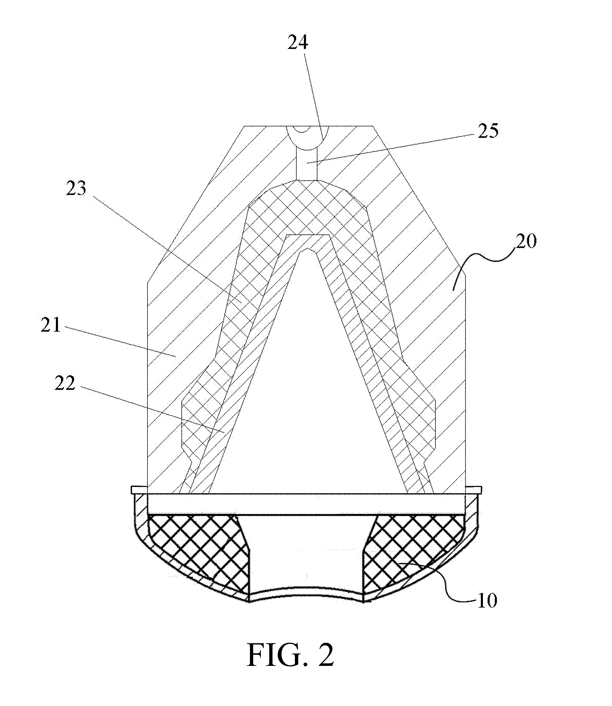
[0013] FIG. 2 is a schematic illustration of an enhanced perforation charge assembly having a shaped charge and the perforation enhancement cap.
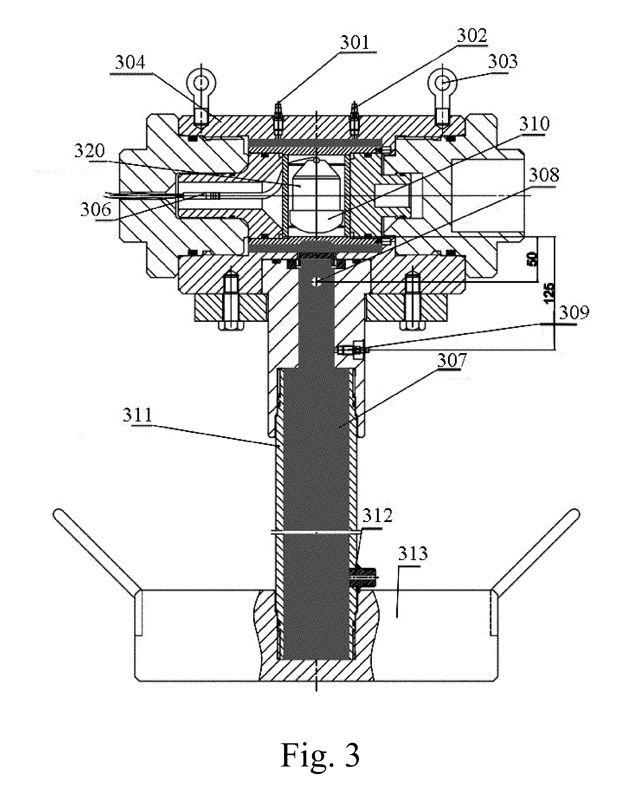
[0014] FIG. 3 is a testing apparatus for monitoring pressure in the perforation tunnel created by detonation of the enhanced perforation charge assembly.
[0015] FIG. 4A is a sectional view of one embodiment of the perforation enhancement cap in this disclosure.
[0016] FIG. 4B is a sectional view of a comparative perforation enhancement cap.
[0017] FIG. 5 shows the pressure surge in a perforation tunnel created in the testing apparatus of FIG. 3 produced by an embodiment of the perforation enhancement cap in this disclosure.
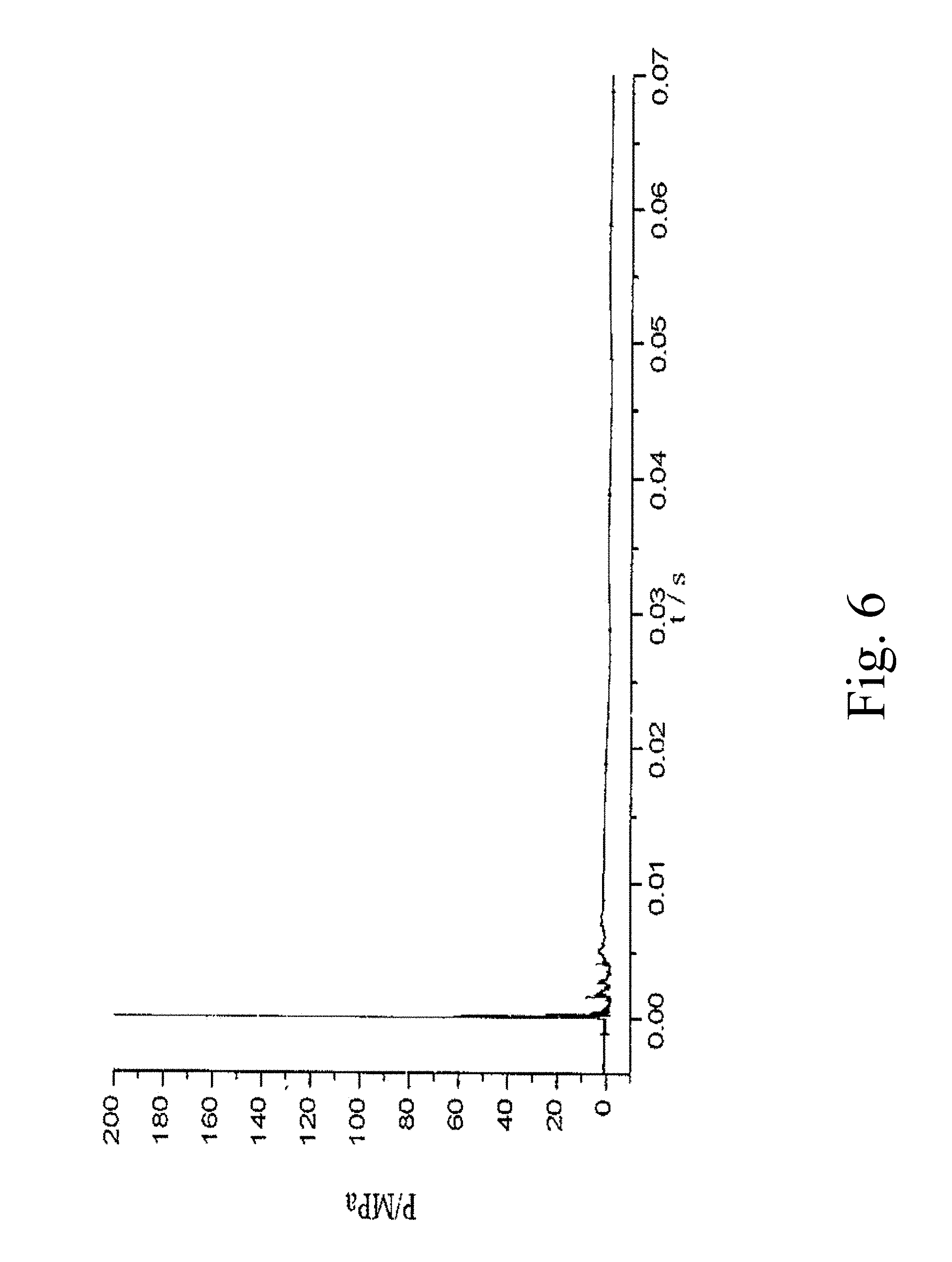
[0018] FIG. 6 shows the pressure surge in a perforation tunnel created in the testing apparatus of FIG. 3 produced by a comparative perforation enhancement cap.
[0019] FIG. 7 compares oil well productions for wells perforated with the enhanced perforation charge assembly with those using regular shaped charges without the perforation enhancement cap.
DETAILED DESCRIPTION OF THE PREFERRED EMBODIMENT
[0020] Reference will now be made in detail to embodiments, examples of which are illustrated in the accompanying drawings, wherein like reference numerals refer to the like elements throughout the several views. In this regard, the present embodiments may have different forms and should not be construed as being limited to the descriptions set forth herein. Accordingly, the embodiments are merely described below, by referring to the figures, to explain aspects of the present description. Terms used herein are for descriptive purposes only and are not intended to limit the scope of the disclosure. The terms "comprises" and/or "comprising" are used to specify the presence of stated elements, steps, operations, and/or components, but do not preclude the presence or addition of one or more other elements, steps, operations, and/or components. The terms "first," "second," and the like may be used to describe various elements, but do not limit the elements. Such terms are only used to distinguish one element from another. These and/or other aspects become apparent and are more readily appreciated by those of ordinary skill in the art from the following description of embodiments of the present disclosure, taken in conjunction with the accompanying drawings. The figures depict embodiments of the present disclosure for purposes of illustration only. One skilled in the art will readily recognize from the following description that alternative embodiments of the structures and methods illustrated herein may be employed without departing from the principles of the disclosure described herein.
[0021] FIGS. 1A and 1B present two views of an embodiment of the perforation enhancement cap 10. The enhancement cap 10 has a shell 11, which has a straight section and a rounded, substantially spherical cap. The tubular straight section has a height (H) in the range of 0-40 mm (e.g., 8-30 mm), an inner diameter (B) in the range of 28-58 mm, and an outer diameter (A) of 30-60 mm. In this embodiment, the thickness of the wall of the ring is 1-2 mm. The radius of the spherical cap (J) is 15-80 mm. The shell 11 houses a pack of propellant 12. The propellant pack 12 has a shape that resembles the top half of a sliced bagel, having a flat round base and a dome-shaped top with a through hole F inside. The propellant pack 12 is fitted into the spherical cap of the shell, where the through hole F in the propellant pack is aligned with, and has a same or smaller diameter than the opening in the spherical cap. The through hole F in the propellant pack is in the shape of a funnel, with a wide, conical frustum top portion and a narrower, straight "stem." The length of the straight stem can be adjusted according to the weight of the propellant pack and is in the range of 0-40 mm. The larger base of the conical frustum opens to the inside of the cap. The opening angle of the conical frustum is in the range of 50.degree.-150.degree.. The weight of the propellant pack is 6-50 grams.
[0022] The propellant has a composition of 30-70 wt % of ammonium perchlorate (e.g., 30-40 wt %, 30-50 wt %, or 50-70 wt %), 10-30 wt % aluminum powder (e.g., 10-15 wt %), 10-15 wt % additive, 3-5 wt % dioctyl sebacate, e.g., 1-4 wt %. The additive is hydroxyl-terminated polybutadiene (HTPB). The additive can also be a mixture of HTPB, N, N'-diphenyl-p-phenylenediamine, and toluene di-isocyanate (TDI) at a weight ratio of (2.85-7):(0.05-0.2):(3-7.8).
[0023] In the first embodiment of the enhancement cap, the propellant pack weighs about 6-20 grams of the propellant. The straight section of the shell 11 is a straight tube having a height (H) in the range of 10-20 mm, e.g., 10-18 mm or 12-16 mm. The inner diameter of the straight tube (B) is in the range of 25-41 mm (e.g. 28-38 mm or 30-38 mm) while its outer diameter (A) is 30-46 mm (e.g., 32-44 mm or 36-42 mm). In this embodiment, the thickness of the wall of the straight tube is 1 mm. The spherical cap has a round hole in the top of a diameter of 10-18 mm. The radius of the spherical cap (J) is 34-49 mm, e.g., 40-48 mm.
[0024] The enhancement cap of the first embodiment, the base radius of the through hole D1 (i.e., the larger base of the conical frustum) of the propellant pack is in the range of 16-35 mm (e.g., 18-30 mm or 20-30 mm) and the diameter of the straight stem D2 is from 10-18 mm (e.g., 12-16 mm), coincide with the hole in the spherical cap. The height of the stem section of the propellant pack is in the range of 1-20 mm, e.g., 1-10 mm or 10-18 mm. The opening angle R1 of the conical frustum in the propellant pack is from 80.degree.-150.degree., for example, 85.degree.-140.degree., 100.degree.-130.degree., 110.degree.-120.degree.. This embodiment of enhancement cap is particularly suitable for a perforating gun having an outer diameter of 2''-3.5''.
[0025] In the second embodiment of the enhancement cap, the propellant pack weighs about 15-50 grams of the propellant. The straight section of the shell 11 has a height (H) in the range of 10-30 mm, e.g., 12-28 mm or 18-26 mm. The inner diameter of the straight tube (B) is in the range of 36-48 mm (e.g. 36-46 mm or 40-44 mm) while its outer diameter (A) is 42-58 mm (e.g., 45-55 mm or 50-55 mm). In this embodiment, the thickness of the wall of the straight tube is 1 mm. The spherical cap has a round hole in the top, which has a diameter of 18-30 mm. The radius of the spherical cap (J) is 49-79 mm, e.g., 50-65 mm or 65-75 mm.
[0026] Further, the base radius of the through hole D1 (i.e., the diameter of the larger base of the conical frustum) of the propellant pack is in the range of 20-45 mm (e.g., 20-40 mm or 25-35 mm) and the diameter of the straight stem D2 is from 18-30 mm (e.g., 20-28 mm). The height of the stem section of the propellant pack is in the range of 10-40 mm, e.g., 15-35 mm or 18-35 mm. The opening angle R1 of the conical frustum in the propellant pack is from 90.degree.-150.degree., for example, 90.degree.-140.degree., 100.degree.-130.degree., or 110.degree.-120.degree.. This embodiment of enhancement cap is particularly suitable for a perforating gun having an outer diameter of 3.5''-5''.
[0027] The enhancement cap 10 can be installed on a shaped charge 20 as shown in FIG. 2. Referring to FIG. 2, the enhancement cap 10 is coaxially mounted on the open-face of shaped charge 20. The shaped charge 20 has a charge case 21, and a metal liner 22 coaxially disposed inside the charge case 21. The charge case 21 and the liner 22 form a cavity in between, which is filled with an explosive material 23. The back end of the charge case 21 has a detonating semi-circle slot 24 for holding a detonating cord. The detonating semi-circle slot 24 is in communication with the explosive material 23 through a detonating hole 25. Upon denotation, the power and heat released from the explosive material 23 collapses and melts the metal liner 22, forming a metal jet penetrating the well casing, cement and shooting into the surrounding formation via the through hole in the enhancement cap 10.
[0028] Without being bound by the theory, it is believed that the energy and heat released by the explosive material 23 disintegrates the propellant pack 10. The propellant travels with the jet through the casing into the formation tunnel, where the propellant releases more energy. With the additional boost of energy from the propellant, the metal jet penetrates deeper into the formation. Also, more fractures are created in the compact zone, increasing permeability. Nevertheless, it is noticed that if the enhancement cap is not properly design, the propellant may not ignite at the proper time or proper location, reducing the effectiveness of the enhancement cap. In the extreme, the propellant may explode in the perforating gun, causing the failure of perforation.
[0029] In this regard, various designs of the enhancement cap have been tested. FIG. 3 shows a device for testing the enhancement cap. The assembly of the shaped charge 320 and the enhancement cap 310 are placed in a pressure proof container 304. Two hooks 303 are provided on the container. The shaped charge is detonated by a detonator 306, generating a metal jet shooting into the target tube 311, which is filled with water 307. The target tube 311 has a pressure relief valve 312 installed thereon and is affixed to a base 313. Sensors 301, 302, 308, and 309 measure the pressure at their respective locations continuously and send the signals to be recorded.
[0030] One aspect of this test is to simulate the pressure profile in the perforation tunnel in the formation. For example, if there is only one pressure peak at the positions of sensors 308 and 309, it would mean that the propellant may have ignited outside the perforation tunnel. If instead there are two pressure spikes, it would indicate that the propellant is ignited inside the perforation tunnel in the formation for the first pressure spike is likely caused by the initial metal jet and the second pressure spike is caused by the ignition of the propellant in the perforation tunnel.
EXAMPLE 1
[0031] FIG. 4A shows an inventive embodiment of the enhancement cap A having a propellant pack A that weighs 12.3 grams. FIG. 4B shows a comparative example--the enhancement cap A having a propellant pack B that weighs 13.5 grams. However, the propellant pack A has a through hole with a diameter of 27 mm at its larger base and a diameter of 16 mm in the straight stem portion. The conical frustum of the through hole in the propellant pack has an opening angle of 85.degree.. In contrast, the propellant pack B has a through hole with a diameter of at its base is 30 mm and a diameter of 7 mm in the stem section.
[0032] FIG. 5 shows a pressure-time curve with propellant pack A, detected by sensor 308. It clearly shows a secondary pressure wave following a first pressure peak. The secondary pressure wave arrived 7.5 ms after the detonation, peaked at between 10 ms to 20 ms, then trailed off to zero at 127 ms. The total duration of the pressurization was 127 ms. First pressure peak caused by the explosive in the shaped charge was over 100 MPa while the secondary pressure wave produced by propellant reached the peak value of 32.8 MPa. The duration of the pressurization above 25 MPa was about 20 ms. More data about these tests are presented in Table 1.
TABLE-US-00001 TABLE 1 2.sup.ndary Pressure Wave 1.sup.st Pressure Peak Stating Measuring Peak Pressure Point Duration Impulse Point (MPa) (MPa) (ms) (ms) (MPa s) Channel 1 >100 32.8 7.51 127 1.53 Sensor 308
[0033] In comparison, the enhancement cap with the propellant pack B was also tested, the results are shown in FIG. 6 and Table 2.
TABLE-US-00002 TABLE 2 1.sup.st Pressure Measuring Peak Duration Impulse Point (MPa) 2.sup.nd Pressure Wave (ms) (MPa S) Channel 1 >200 negligible None None Sensor 308
[0034] As shown in FIG. 6 and Table 2, the detonation created only one pressure surge with no secondary pressure wave. Although the peak pressure surpassed 200 MPa, it only lasted a few milliseconds. Therefore, propellant pack B would not be able to create more fracturing in the compact zone surround the perforation tunnel.
EXAMPLE 2
[0035] The performance of enhancement caps A and B were tested by shooting at steel bars. In these experiments, caps A and B were respectively combined with the same type of shaped charge. The enhanced perforation charge assembly was placed on top of a steel bar and detonated, creating a perforation hole in the steel bar.
[0036] Table 3 compares the results from the shaped charge with or without the enhancement cap A.
TABLE-US-00003 TABLE 3 Penetration Avg. Avg. Steel Depth Opening Size Depth Diameter Cylinder No. Charge Configuration (mm) (mm) (mm) (mm) 1 without Cap A 178 11.1 .times. 11.7 169 11 2 without Cap A 160 10.4 .times. 11.1 3 with Cap A 180 12.8 .times. 11 171 12 4 with Cap A 163 12.3 .times. 12.1 5 with Cap A 172 12 .times. 12.4 6 with Cap A 169 11.6 .times. 12.3
[0037] Table 4 compares the results from the shaped charge with or without the enhancement cap B.
TABLE-US-00004 TABLE 4 Steel Target Charge Penetration Opening Size No. Configuration Depth (mm) (mm) 7 with Cap B 131 10.4 * 11.2 8 with Cap B 143 11.3 * 10.9 9 with Cap B 137 10.1 * 10.8 Average 137 10.8
[0038] The shaped charge without any enhancement cap created perforation tunnels about 169 mm long on average and openings about 11 mm in diameter on average. The shaped charge equipped with the enhancement cap A created perforation tunnels having an average length of 171 mm and an average opening diameter of 12 mm. In comparison, the shaped charge equipped with the enhancement cap B created an average penetration length of 137 mm and an average opening diameter of 11 mm.
[0039] It is believed that the perforation tunnel in steel bar was mainly created by the first pressure peak because the second pressure wave does not have sufficient energy to lengthen or enlarge the tunnel in steel. Therefore, the results from the shape charge with cap A is only slightly better than that of the shaped charge alone. However, the penetration by the shaped charge with cap B is about 20% less than by the shaped charge only while the size of the opening in the steel bar was practically the same. The result suggests that the enhancement cap B may have hindered the metal jet, possibly due to a premature detonation that in fact reduced the peak pressure of the metal jet.
[0040] These experiments again confirmed that the perforation performance is heavily dependent upon the shape of the propellant cap.
EXAMPLE 3
[0041] The enhancement cap described in this disclosure has been used on a total of 240,000 charges in over 2,000 vertical oil wells by China Yanchang Petroleum. There was no explosion accident or other safety issues. The average yield of crude oil for those wells was increased by 28.04% by using the enhancement cap.
[0042] FIG. 7 shows oil output of six wells from same production field in a period of 34 months from 2009 to 2012. Three among the six wells were perforated using shaped charges with an enhancement cap, whose outputs are traced in solid lines. The other three were perforated with shaped charges only, whose outputs are traced in dash lines. Otherwise, these wells were located in the same block, same formation, and operated under the same conditions.
[0043] Total oil output from test wells using the enhancement cap was 4364.16 T while those did not employ enhancement wells have a total output of 1318.51 T for the test period.
[0044] It is to be understood that the exemplary embodiments described herein are that for presently preferred embodiments and are not limiting. Descriptions of features or aspects within each embodiment should typically be considered as available for other similar features or aspects in other embodiments.
* * * * *
D00000
D00001
D00002
D00003
D00004
D00005
D00006
D00007
D00008
XML
uspto.report is an independent third-party trademark research tool that is not affiliated, endorsed, or sponsored by the United States Patent and Trademark Office (USPTO) or any other governmental organization. The information provided by uspto.report is based on publicly available data at the time of writing and is intended for informational purposes only.
While we strive to provide accurate and up-to-date information, we do not guarantee the accuracy, completeness, reliability, or suitability of the information displayed on this site. The use of this site is at your own risk. Any reliance you place on such information is therefore strictly at your own risk.
All official trademark data, including owner information, should be verified by visiting the official USPTO website at www.uspto.gov. This site is not intended to replace professional legal advice and should not be used as a substitute for consulting with a legal professional who is knowledgeable about trademark law.