Stacked-plate Heat Exchanger
Irmler; Klaus ; et al.
U.S. patent application number 16/090201 was filed with the patent office on 2019-04-18 for stacked-plate heat exchanger. This patent application is currently assigned to Mahle International GmbH. The applicant listed for this patent is Mahle International GmbH. Invention is credited to Klaus Irmler, Michael Schmidt.
| Application Number | 20190113285 16/090201 |
| Document ID | / |
| Family ID | 58455054 |
| Filed Date | 2019-04-18 |


| United States Patent Application | 20190113285 |
| Kind Code | A1 |
| Irmler; Klaus ; et al. | April 18, 2019 |
STACKED-PLATE HEAT EXCHANGER
Abstract
A stacked-plate heat exchanger may include a plurality of stacked plates stacked on top of each other along a stacking direction. A channel structure, through which a fluid may be flowable, may be formed in at least one stacked plate. From a top view of the at least one stacked plate, the channel structure may have at least one fluid channel along the stacking direction that may have at least one channel section with a zigzag-like geometry.
| Inventors: | Irmler; Klaus; (Tuebingen, DE) ; Schmidt; Michael; (Bietigheim-Bissingen, DE) | ||||||||||
| Applicant: |
|
||||||||||
|---|---|---|---|---|---|---|---|---|---|---|---|
| Assignee: | Mahle International GmbH Stuttgart DE |
||||||||||
| Family ID: | 58455054 | ||||||||||
| Appl. No.: | 16/090201 | ||||||||||
| Filed: | March 30, 2017 | ||||||||||
| PCT Filed: | March 30, 2017 | ||||||||||
| PCT NO: | PCT/EP2017/057536 | ||||||||||
| 371 Date: | September 28, 2018 |
| Current U.S. Class: | 1/1 |
| Current CPC Class: | F28D 9/0025 20130101; F28D 9/0031 20130101; F28F 3/048 20130101; F28D 9/0043 20130101; F28F 3/08 20130101; F28F 3/046 20130101 |
| International Class: | F28D 9/00 20060101 F28D009/00; F28F 3/04 20060101 F28F003/04 |
Foreign Application Data
| Date | Code | Application Number |
|---|---|---|
| Mar 31, 2016 | DE | 10 2016 205 353.1 |
Claims
1. A stacked-plate heat exchanger comprising: a plurality of stacked plates stacked on top of each other along a stacking direction; wherein a channel structure, through which a fluid is flowable, is formed in at least one stacked plate; wherein, from a top view of the at least one stacked plate, the channel structure has at least one fluid channel along the stacking direction that has at least one channel section with a zigzag-like geometry.
2. The stacked-plate heat exchanger according to claim 1, wherein the at least one channel section has a first partial section and a second partial section forming an angle between 90.degree. and 165.degree..
3. The stacked-plate heat exchanger according to claim 1, wherein the first and the second partial sections are respectively formed substantially rectilinear and continue into one another via a curved formed transition section.
4. The stacked-plate heat exchanger according to claim 1, wherein the at least one fluid channel is formed in a meander-like manner and has a plurality of channel sections each with a zigzag-like geometry.
5. The stacked-plate heat exchanger according to claim 1, wherein at least one fluid channel has a plurality of U-shaped channel sections, wherein at least one channel section with the zigzag-like geometry is provided between at least two U-shaped channel sections adjacent along an extent direction of the fluid channel.
6. The stacked-plate heat exchanger according to claim 5, wherein two channel sections with the zigzag-like geometry and following one another along the extent direction are provided between the at least two U-shaped channel sections.
7. The stacked-plate heat exchanger according to claim 1, wherein the at least one fluid channel includes at least two fluid channels extending substantially parallel to and at a distance from one another.
8. The stacked-plate heat exchanger according to claim 7, wherein, between the at least two fluid channels, at least one connecting channel is formed in a region of the at least one channel section, the at least one connecting channel fluidically connecting the at least two fluid channels to one another.
9. The stacked-plate heat exchanger according to claim 8, wherein the at least one connecting channel includes a plurality of connecting channels arranged at a distance from one another along an extent direction of the at least two fluid channels.
10. The stacked-plate heat exchanger according to claim 9, wherein the plurality of connecting channels fluidically connect all of the at least two fluid channels to one another.
11. The stacked-plate heat exchanger according to claim 1, wherein one of: the channel structure is formed to be flowed through by water, and the at least one fluid channel has a cross-sectional area between 2 mm.sup.2 and 8 mm.sup.2 in a cross-section of the at least one stacked plate perpendicular to an extent direction of the at least one fluid channel; the channel structure is formed to be flowed through by ethanol, and the cross-sectional area of the at least one fluid channel is between 3 mm.sup.2 and 15 mm.sup.2 in the cross-section of the at least one stacked plate; the channel structure is formed to be flowed through by, and the cross-sectional area of the at least one fluid channel is between 6 mm.sup.2 and 20 mm.sup.2 in the cross-section of the at least one stacked plate; or the channel structure is formed to be flowed through by hydrofluorocarbons, and the cross-sectional area of the at least one fluid channel is between 15 mm.sup.2 and 40 mm.sup.2 in the cross-section of the at least one stacked plate.
12. The stacked-plate heat exchanger according to claim 1, wherein the channel structure includes at least one of corrugation-like elevations and depressions in the at least one stacked plate.
13. The stacked-plate heat exchanger according to claim 1, wherein at least two stacked plates each has a channel structure.
14. The stacked-plate heat exchanger according to claim 7, further comprising a shared fluid inlet for distributing the fluid to the at least two fluid channels, and a shared fluid outlet for directing the fluid out after flowing through the at least two fluid channels.
15. The stacked-plate heat exchanger according to claim 1, wherein the at least one fluid channel and the at least one channel section are configured such that the fluid is substantially entirely in liquid phase when in the at least one channel section.
16. The stacked-plate heat exchanger according to claim 1, wherein the at least one fluid channel includes at least one other channel section different from the at least channel section with a zigzag-like geometry that does not have a zigzag-like geometry.
17. The stacked-plate heat exchanger according to claim 16, wherein the at least one other channel has a rectilinear geometry.
18. The stacked-plate heat exchanger according to claim 7, wherein the at least two fluid channels include three fluid channels.
19. A stacked-plate heat exchanger comprising: a plurality of stacked plates stacked on top of each other along a stacking direction; wherein at least one of the stacked plates includes a channel structure through which a fluid is flowable; and wherein the channel structure includes at least two fluid channels along the stacking direction extending substantially parallel to and at a distance from one another, and at least one connecting channel fluidically connecting the at least two fluid channels to one another, the at least two fluid channels each having at least one channel section with a zigzag-like geometry.
20. The stacked-plate heat exchanger according to claim 19, wherein the at least one channel section has a first partial section and a second partial section forming an angle between 90.degree. and 165.degree..
Description
CROSS REFERENCE TO RELATED APPLICATIONS
[0001] This application claims priority to International Patent Application No. PCT/EP2017/057536, filed on Mar. 30, 2017, and German Patent Application No. DE 10 2016 205 353.1, filed on Mar. 31, 2016, the contents of both of which are hereby incorporated by reference in their entirety.
TECHNICAL FIELD
[0002] The invention relates to a stacked-plate heat exchanger.
BACKGROUND
[0003] Stacked-plate heat exchangers come into use as so-called exhaust gas evaporators in the exhaust gas aftertreatment of internal combustion engines. Such an exhaust gas evaporator enables a recovery of thermal energy from the exhaust gases which are discharged from the internal combustion engine. In an exhaust gas evaporator, heat is extracted from the exhaust gas and is fed to a coolant or refrigerant, the so-called working medium, which is typically evaporated here.
[0004] Such a stacked-plate heat exchanger is known for example from DE 10 2009 012 493 A1.
[0005] In order to achieve as high an efficiency as possible in the heat recovery, an optimized geometry of the channel structure in which the working medium is directed through the evaporator or respectively stacked-plate heat exchanger is of central importance.
SUMMARY
[0006] It is an object of the present invention to provide an improved embodiment for a stacked-plate heat exchanger, which in particular has an improved efficiency.
[0007] This problem is solved by the subject of the independent claims. Preferred embodiments are the subject of the dependent claims.
[0008] Accordingly, it is a basic idea of the invention to provide the channel structure, formed in the stacked-plate heat exchanger, which is to be flowed through by a fluid--the working medium of the heat exchanger--partially with a zigzag-like channel geometry. The changes to the flow direction of the working medium, entailed thereby, when flowing through the zigzag-like channel geometry, are accompanied by an increased heat exchange between the working medium and the exhaust gas which is directed through the stacked-plate heat exchanger. Therefore, such a zigzag-like channel geometry is suitable in a region of the channel structure in which the working medium is present in liquid phase. This is because in this region, at low speeds of flow of the working medium, the heat transmission to the working medium is itself reduced. The zigzag-like channel geometry essential to the invention can at least compensate this reduced heat transmission with working medium present in liquid phase, and therefore leads, as a result, to an improved efficiency of the heat exchanger.
[0009] In the regions of the channel structure in which the working medium is two-phase, therefore is also present in gaseous form, the heat transmission is also sufficiently high without a zigzag-like geometry, so that there the said zigzag-like channel geometry can be dispensed with. Therefore, in these regions of the channel structure, an unnecessary pressure loss in the working medium, which always accompanies the zigzag geometry, is avoided.
[0010] A stacked-plate heat exchanger according to the invention comprises a plurality of stacked plates which are stacked on top of each other along a stacking direction. A channel structure, which is to be flowed through by a fluid, is formed in at least one stacked plate. The channel structure, when the stacked plate is viewed from above, comprises at least one fluid channel along the stacking direction, said fluid channel having at least one channel section with a zigzag-like geometry.
[0011] In a preferred embodiment, the at least one channel section with a zigzag-like geometry has a first partial section, which continues into a second partial section. The two partial sections form together an angle of between 90.degree. and 165.degree.. Experimental investigations have shown that with the said angle range a particularly high heat exchange can be achieved between the working medium and the exhaust gas.
[0012] In an advantageous further development, the first and the second partial section are configured so as to be substantially rectilinear along the stacking direction, when viewed from above, and continue into one another by means of a curved formed transition section. By means of such a geometry, an undesired pressure loss in the working medium when flowing through the fluid channel can be kept low.
[0013] Particularly preferably, the at least one fluid channel of the channel structure is formed in a meander-like manner and has a plurality of channel sections with a zigzag-like geometry. Such a geometry permits the arrangement of the fluid channel on a stacked plate with relatively small surface dimensions. Therefore, the stacked-plate heat exchanger can be realized with particularly compact exterior dimensions.
[0014] In a further preferred embodiment, at least one fluid channel has a plurality of U-shaped channel sections.
[0015] In this variant, at least one channel section with a zigzag-like geometry is provided between at least two adjacent U-shaped channel sections along an extent direction of the at least one fluid channel. This variant also permits a high heat exchange with, at the same time, a small installation space requirement.
[0016] Because it is likewise able to be realized in a particularly compact construction, a variant may be considered to be particularly preferred in which, between the at least two U-shaped channel sections following one another along the extent direction of the at least one fluid channel, two channel sections with a zigzag-like geometry are provided following one another along the extent direction.
[0017] In an advantageous further development, the channel structure comprises at least two fluid channels extending substantially parallel to and at a distance from one another. In this way, a high compressive strength can be ensured in the individual fluid channels. For a variety of working media, such as for instance cyclopentane, ethanol, acetone, it proves to be advantageous if precisely three fluid channels are provided, which extend substantially parallel to and at a distance from one another.
[0018] In a further advantageous further development, at least one connecting channel is formed between the at least two fluid channels, which connecting channel is provided with a zigzag-like geometry in the region of the channel section and fluidically connects the at least two fluid channels with one another. This enables a pressure equalization of the fluid pressure which is present in the working medium in the individual fluid channels. This, in turn, promotes a laterally particularly homogeneous heat exchange between working medium or respective the fluid, and the exhaust gas.
[0019] Particularly preferably, a plurality of connecting channels is provided, which are arranged at a distance from one another along the extent direction of the at least two fluid channels. In this way, the desired pressure equalization can be guaranteed over the entire extent of the fluid channels.
[0020] In a further advantageous further development, at least one connecting channel, preferably respectively all connecting channels, fluidically connects to one another all the fluid channels which are present. This provision also promotes a pressure equalization in the working medium or respectively fluid which is advantageous for a homogeneous heat exchange.
[0021] In another preferred embodiment, the channel structure is formed to be flowed through by water. For this, all the fluid channels which are present have, together, in a cross-section of the stacked plate perpendicularly to the extent direction of the fluid channels, a cross-section area of between 2 mm.sup.2 and 8 mm.sup.2. Alternatively thereto, the channel structure is formed to be flowed through by ethanol. For this, all the fluid channels which are present have, together, in the cross-section of the stacked plate perpendicularly to the extent direction of the fluid channels, a cross-section area of between 3 mm.sup.2 and 15 mm.sup.2. It is also conceivable to use a mixture of ethanol and water. Alternatively thereto, the channel structure can be formed to be flowed through by cyclopentane. In this case, all the fluid channels which are present have, together, in the cross-section of the stacked plate perpendicularly to the extent direction of the fluid channels, a cross-section area of between 6 mm.sup.2 and 20 mm.sup.2. Alternatively thereto, the use of acetone is also conceivable. Alternatively thereto, the channel structure is formed to be flowed through by hydrofluorocarbons (HFC). In this variant, all the fluid channels which are present have, together, in a cross-section of the stacked plate perpendicularly to the extent direction of the fluid channels, a cross-section area of between 15 mm.sup.2 and 40 mm.sup.2. Depending on the choice of the working medium, therefore, an individual design of the cross-section area of the individual fluid channels takes place. In this way, an efficient heat exchange is ensured, with, at the same time, little pressure loss in the working medium. All the named substances can also be used as a mixture with an oil.
[0022] A further preferred embodiment proves to be technically particularly simple to realize and therefore to be produced at a favourable cost, in which the channel structure is formed by corrugation-like elevations or depressions present in the stacked plate. This permits a realizing of the stacked plates with the channel structure essential to the invention as shaped sheet metal parts, in particular by means of deep drawing.
[0023] In a further preferred embodiment, a channel structure is present in at least two stacked plates. The more stacked plates are provided with a channel structure with the zigzag-like flow geometry essential to the invention, the higher is the efficiency which is able to be achieved with the stacked-plate heat exchanger, in particular if the latter is used as an exhaust gas evaporator in interaction with an internal combustion engine.
[0024] Expediently, the stacked-plate heat exchanger can have a shared fluid inlet for distributing the fluid to the at least two, preferably three, fluid channels, and a shared fluid outlet for directing the fluid out after flowing through the respective fluid channels. This provision simplifies the structure of the stacked-plate heat exchanger, in particular when several separate fluid channels are provided.
[0025] Further important features and advantages of the invention will emerge from the subclaims, from the drawings and from the associated figure description with the aid of the drawings.
[0026] It shall be understood that the features mentioned above and to be explained further below are able to be used not only in the respectively indicated combination, but also in other combinations or in isolation, without departing from the scope of the present invention.
[0027] Preferred example embodiments of the invention are illustrated in the drawings and are explained further in the following description, wherein the same reference numbers refer to identical or similar or functionally identical components.
BRIEF DESCRIPTION OF THE DRAWINGS
[0028] There are shown, respectively diagrammatically:
[0029] FIG. 1 an individual stacked plate of the stacked-plate heat exchanger with the channel structure according to the invention, in a perspective view,
[0030] FIG. 2 a detail illustration of the channel structure of FIG. 1 in a top view onto the stacked plate,
[0031] FIG. 3 a variant of the stacked plate of FIGS. 1 and 2, with a channel structure which comprises three fluid channels, in a cross-section,
[0032] FIG. 4 the stacked-plate heat exchanger with several stacked plates stacked on top of each other, in a perspective illustration.
DETAILED DESCRIPTION
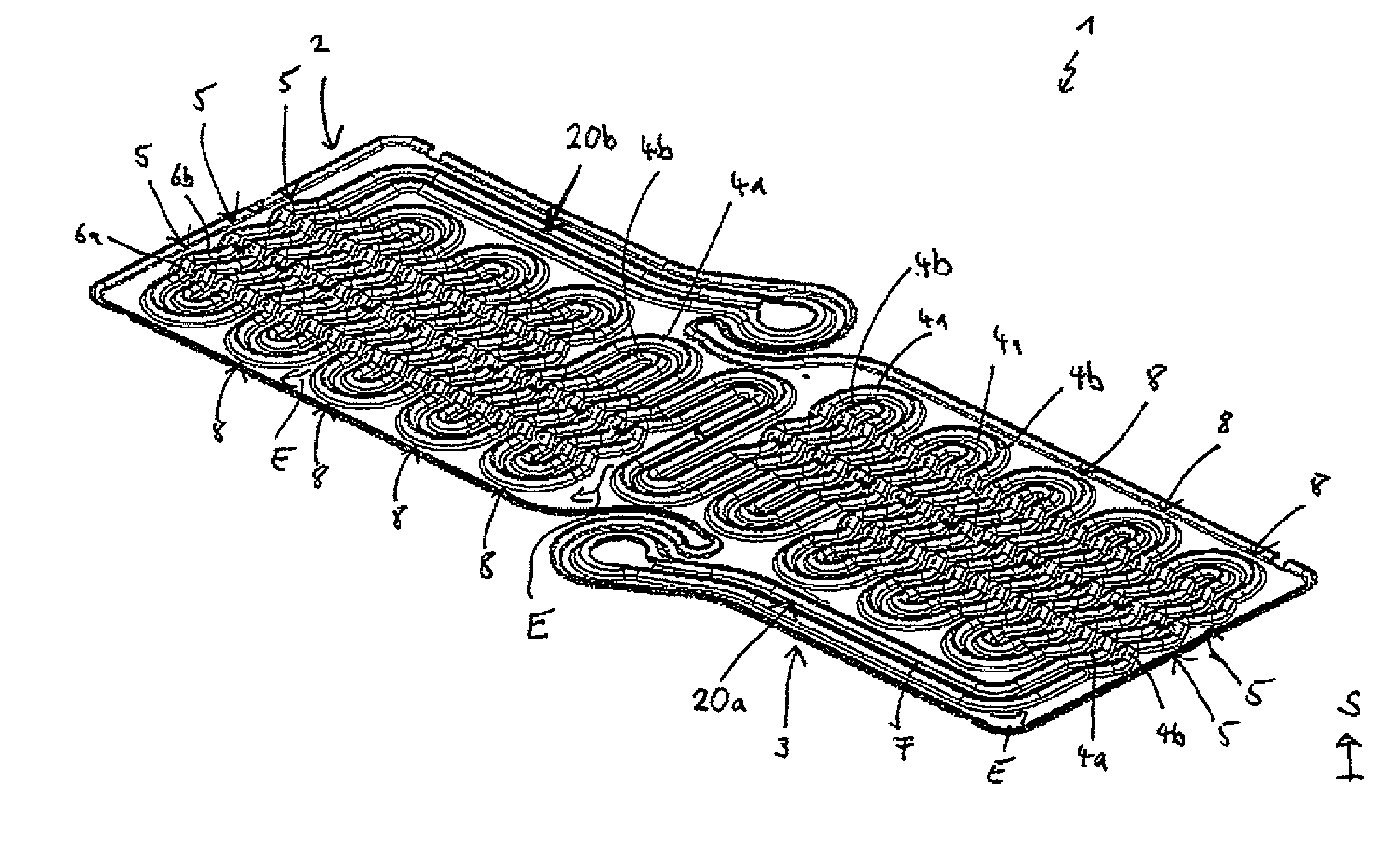
[0033] FIG. 1 illustrates by way of example an individual stacked plate 2 of a stacked-plate heat exchanger 1 according to the invention, in a perspective illustration.
[0034] In the stacked plate 2 shown in FIG. 1, a channel structure 3 is formed which is to be flowed through by a fluid F. The channel structure 3 comprises two fluid channels 4a, 4b which, when the stacked plate 2 is viewed from above, extend along the stacking direction S substantially parallel to and at a distance from one another. The channel structure 3 with the fluid channels 4a, 4b is formed by corrugation-like elevations or depressions 10 formed in the stacked plate 2. Each stacked plate 2 is covered in stacking direction S on both sides with two cover plates 11a, 11b lying opposite one another, as can be seen from FIG. 3 which shows the stacked plate 2 in a sectional illustration. Accordingly, the two cover plates 11a, 11b delimit the channel structures 3 formed in the stacked plate 2 in and contrary to the stacking direction S (cf. FIG. 2). The two cover plates 11a, 11b can be soldered to the respective stacked plate 2.
[0035] For the formation of the stacked-plate heat exchanger 1, several stacked plates 2 with respective cover plates 11a, 11b can be stacked on top of each other. This is shown in FIG. 4, which shows the stacked-plate heat exchanger 1 in a perspective partial illustration. The individual stacked plates 2 with the cover plates 11a, 1b are arranged at a distance from one another in the stacking direction S, wherein adjacent cover plates 11a, 11b in stacking direction S rest against one another by means of a respective rib structure 12, which is not illustrated in closer detail in FIG. 4. The intermediate spaces 13 formed in the region of the rib structures 12 between adjacent cover plates 11a, 11b can be flowed through by an exhaust gas 14, which is in heat exchange with the fluid F flowing through the channel structures 3 of the stacked plates 2.
[0036] Observing FIG. 1 again now, it will be seen that the two fluid channels 4a, 4b of the channel structure 3 are formed respectively in a meander-like manner. Each of the two fluid channels 4a, 4b has channel sections 5 with respectively a zigzag-like geometry. The stacked-plate heat exchanger 1 can have, in addition, a shared fluid inlet for distributing the fluid F to the two fluid channels 4a, 4b, and a shared fluid outlet for directing the fluid F out after flowing through the two fluid channels 4a, 4b.
[0037] FIG. 2 is a detail illustration of FIG. 1 in the region of channel sections 5 with a respectively zigzag-like geometry. As can be seen from FIG. 2, a channel section 5 with a zigzag-like geometry, present in the channel structure 3, has a first partial section 6a which continues into a second partial section 6b by means of a transition section 7. The first and the second partial section 6a, 6b are respectively configured to be substantially rectilinear, the transition section 7, on the other hand, is formed so as to be curved. The two partial sections 6a, 6b are preferably arranged at an angle of between 90.degree. and 165.degree. to one another.
[0038] As FIG. 1 shows, the two fluid channels 4a, 4b respectively comprise not only channel sections 5 with a zigzag-like geometry, but respectively also have a plurality of U-shaped channel sections 8. Between two U-shaped channel sections 8 adjacent along an extent direction E of the fluid channels 4a, 4b, the channel sections 5 are formed with a zigzag-like geometry.
[0039] The channel sections 5 with a zigzag-like geometry are arranged in the stacked-plate heat exchanger 1 such that in the channel sections 5 the fluid F is present entirely in liquid phase. In addition, the two fluid channels 4a, 4b can respectively have two channel sections 20a, 20b that are different from the channel sections 5 with a zigzag-like geometry, in which the fluid channels 4a, 4b do not have a zigzag-like geometry, but rather can be formed so as to be rectilinear or differently.
[0040] As FIG. 2 demonstrates, connecting channels 9 are formed between the two fluid channels 4a, 4b running at a distance from one another, in the region of the channel sections 5 with a zigzag-like geometry. The connecting channels 9 fluidically connect the fluid channels 4a, 4b to one another and are arranged, for this, at a distance from one another along the extent direction E of the fluid channels 4a, 4b.
[0041] FIG. 3 shows a variant of the example of FIG. 1. In the example of FIG. 3, as already mentioned above, a stacked plate 2 of the stacked-plate heat exchanger 1 is illustrated in a cross-section perpendicularly to the extent direction E. In the variant according to FIG. 3, the channel structure 3 comprises a first, a second and a third fluid channel 4a, 4b, 4c, therefore three fluid channels 4a, 4b, 4c.
[0042] As FIG. 3 demonstrates, the first fluid channel 4a in the cross-section of FIG. 3 has a cross-sectional area A.sub.1, the second fluid channel 4b has a cross-sectional area A.sub.2, and the third fluid channel 4c has a cross-sectional area A.sub.3. The total A of the individual cross-sectional areas in the case of the three fluid channels 4a, 4b, 4c which are present results as A=A.sub.1+A.sub.2+A.sub.3.
[0043] Preferably, the cross-sectional area A is adapted to the working medium flowing through the channel structure 3, therefore to the fluid which is used. In this way, an efficient heat exchange can be ensured with, at the same time, a small pressure loss in the working medium/fluid.
[0044] If the channel structure 3 is to be flowed through by fluid/working medium, a range of values of between 2 mm.sup.2 and 8 mm.sup.2 is recommended for the cross-sectional area A defined above.
[0045] If the channel structure 3 is to be flowed through by ethanol as fluid/working medium, then a range of values of between 3 mm.sup.2 and 15 mm.sup.2 proves to be advantageous for the cross-sectional area A defined above. The use of a mixture of ethanol and water is also conceivable.
[0046] If the channel structure 3 is to be flowed through by cyclopentane as fluid/working medium, then a range of values of between 6 mm.sup.2 and 20 mm.sup.2 is recommended for the cross-sectional area A defined above. Acetone can be used as an alternative substance to cyclopentane.
[0047] If the channel structure 3 is to be flowed through by hydrofluorocarbons (HFC) as fluid/working medium, then a range of values of between 15 mm.sup.2 and 40 mm.sup.2 is recommended for the cross-sectional area A defined above.
[0048] In further variants, a mixture of one of the previously mentioned substances with an oil is also possible.
* * * * *
D00000
D00001
D00002
D00003
XML
uspto.report is an independent third-party trademark research tool that is not affiliated, endorsed, or sponsored by the United States Patent and Trademark Office (USPTO) or any other governmental organization. The information provided by uspto.report is based on publicly available data at the time of writing and is intended for informational purposes only.
While we strive to provide accurate and up-to-date information, we do not guarantee the accuracy, completeness, reliability, or suitability of the information displayed on this site. The use of this site is at your own risk. Any reliance you place on such information is therefore strictly at your own risk.
All official trademark data, including owner information, should be verified by visiting the official USPTO website at www.uspto.gov. This site is not intended to replace professional legal advice and should not be used as a substitute for consulting with a legal professional who is knowledgeable about trademark law.