Pulse-coupled Pump
XI; Daguang ; et al.
U.S. patent application number 15/782838 was filed with the patent office on 2019-04-18 for pulse-coupled pump. This patent application is currently assigned to Zhejiang FAI Electronics Co., Ltd.. The applicant listed for this patent is Zhejiang FAI Electronics Co., Ltd.. Invention is credited to Qijiang LE, Daguang XI, Luming XU, Yanxiang YANG.
| Application Number | 20190112959 15/782838 |
| Document ID | / |
| Family ID | 66096346 |
| Filed Date | 2019-04-18 |


| United States Patent Application | 20190112959 |
| Kind Code | A1 |
| XI; Daguang ; et al. | April 18, 2019 |
PULSE-COUPLED PUMP
Abstract
A pulse-coupled pump includes a pump body, a low-pressure pump, a high-pressure pump, and a solenoid. The low-pressure pump comprises an armature, an armature sleeve and a rectifying valve. The high-pressure pump comprises a plunger, a sleeve, an inlet valve and a delivery valve. The high-pressure pump is coupled with the low-pressure pump through the armature. The armature, located in the armature sleeve, performs a reciprocating motion driven by magnetic field force of the solenoid, which drives the plunger pump and a forms two-way pulsating liquid. The two-way pulsating liquid can form a directional flow through a rectifying valve. The armature and the armature sleeve are made of magnetically permeable material. The armature sleeve has a non-magnetic gap. The front end of the armature is located near the magnetic gap. The inlet valve is located upstream of the directional liquid flow.
| Inventors: | XI; Daguang; (Hangzhou, CN) ; XU; Luming; (Hangzhou, CN) ; LE; Qijiang; (Hangzhou, CN) ; YANG; Yanxiang; (Hangzhou, CN) | ||||||||||
| Applicant: |
|
||||||||||
|---|---|---|---|---|---|---|---|---|---|---|---|
| Assignee: | Zhejiang FAI Electronics Co.,
Ltd. Hangzhou CN |
||||||||||
| Family ID: | 66096346 | ||||||||||
| Appl. No.: | 15/782838 | ||||||||||
| Filed: | October 12, 2017 |
| Current U.S. Class: | 1/1 |
| Current CPC Class: | F01N 3/0253 20130101; F04B 53/1005 20130101; F04B 11/0025 20130101; F04B 17/046 20130101; F01N 3/2066 20130101; F04B 5/02 20130101; F02M 59/102 20130101; F01N 3/035 20130101; F01N 2610/1433 20130101; F04B 23/06 20130101; F01N 13/0097 20140603; F04B 17/04 20130101; F01N 3/2892 20130101; F01N 2610/03 20130101 |
| International Class: | F01N 3/20 20060101 F01N003/20; F01N 3/025 20060101 F01N003/025; F04B 53/10 20060101 F04B053/10; F04B 23/06 20060101 F04B023/06; F04B 17/04 20060101 F04B017/04; F04B 11/00 20060101 F04B011/00; F01N 3/28 20060101 F01N003/28 |
Claims
1. A pulse-coupled pump, comprising a pump body, in which a low-pressure pump, a high-pressure pump, and a solenoid is disposed, wherein the low-pressure pump comprises an armature, an armature sleeve and a rectifying valve, wherein the high-pressure pump comprises a plunger, a sleeve, an inlet valve and a delivery valve, wherein the high-pressure pump is coupled with the low-pressure pump through the armature, wherein the armature, which is located in the armature sleeve, performs a reciprocating motion driven by the magnetic field force of the solenoid, which drives the working of a plunger pump to produce a two-way pulsating liquid, wherein the two-way pulsating liquid can form a directional flow through a rectifying valve, and wherein the inlet valve is located upstream of the directional liquid flow.
2. The pulse-coupled pump according to claim 1, wherein the rectifying valve is a one-way valve.
3. The pulse-coupled pump according to claim 2, wherein the rectifying valve is a diaphragm valve.
4. The pulse-coupled pump according to claim 3, wherein the sleeve is moved in synchronism with the armature, and the plunger is fixed relative to the pump body.
5. The pulse-coupled pump according to claim 3, wherein the plunger is moved in synchronism with the armature, and the sleeve is fixed relative to the pump body.
6. The pulse-coupled pump according to claim 4, wherein it comprises a rear limiter and a front limiter fixed relative to the pump body, and the armature moves in a fixed way between the front limiter and the rear limiter, to obtain fixed liquid output of single pulse.
7. The pulse-coupled pump according to claim 5, wherein it comprises a rear limiter and a front limiter fixed relative to the pump body, and the armature moves in a fixed way between the front limiter and the rear limiter, to obtain fixed liquid output of single pulse.
8. The pulse-coupled pump according to claim 4, wherein it comprises an external circulating passage located outside the pump body, the external circulating passage is connected in parallel with the low-pressure pump in the pump body to form a space for liquid circulation flow.
9. The pulse-coupled pump according to claim 5, wherein it comprises an external circulating passage located outside the pump body, the external circulating passage is connected in parallel with the low-pressure pump in the pump body to form a space for liquid circulation flow.
10. The pulse-coupled pump according to claim 6, wherein it comprises an external circulating passage located outside the pump body, the external circulating passage is connected in parallel with the low-pressure pump in the pump body to form a space for liquid circulation flow.
11. The pulse-coupled pump according to claim 7, wherein it comprises an external circulating passage located outside the pump body, the external circulating passage is connected in parallel with the low-pressure pump in the pump body to form a space for liquid circulation flow.
12. The pulse-coupled pump according to claim 8, wherein it comprises a gas-liquid separation chamber, and the gas-liquid separation chamber is connected in series to the external circulating passage.
13. The pulse-coupled pump according to claim 9, wherein it comprises a gas-liquid separation chamber, and the gas-liquid separation chamber is connected in series to the external circulating passage.
14. The pulse-coupled pump according to claim 10, wherein it comprises a gas-liquid separation chamber, and the gas-liquid separation chamber is connected in series to the external circulating passage.
15. The pulse-coupled pump according to claim 11, wherein it comprises a gas-liquid separation chamber, and the gas-liquid separation chamber is connected in series to the external circulating passage.
16. The pulse-coupled pump according to claim 12, wherein it comprises a liquid feed filter, and the gas-liquid separation chamber is communicated with the clean space of the filter.
17. The pulse-coupled pump according to claim 13, wherein it comprises a liquid feed filter, and the gas-liquid separation chamber is communicated with the clean space of the filter.
18. The pulse-coupled pump according to claim 14, wherein it comprises a liquid feed filter, and the gas-liquid separation chamber is communicated with the clean space of the filter.
19. The pulse-coupled pump according to claim 15, wherein it comprises a liquid feed filter, and the gas-liquid separation chamber is communicated with the clean space of the filter.
Description
FIELD OF THE INVENTION
[0001] The present invention relates to a liquid metering technique, particularly to a liquid injection metering technique of engine, and more particularly to an engine fuel injection device, engine exhaust gas purification nitric oxide selective catalytic reduction (SCR) system and fuel injection regeneration system of diesel engine tail gas particulate filtration (DPF).
BACKGROUND
[0002] Liquid metering technique is a basic technique for modern industry, and its applications include engine fuel injection system (including Gasoline Direct Injection (GDI) and Multi-point Injection (MPI)), engine exhaust gas purification nitric oxide selective catalytic reduction (SCR) urea aqueous solution injection system, and injection regeneration system of diesel engine tail gas particulate filtration (DPF), etc. These systems have high requirements for the metering of liquid.
[0003] Taking the solenoid plunger pump as an example, the quantitative delivery of working fluid is achieved by solenoid-driven armature reciprocating motion; however, the two-way pulse fluid waves of liquid in the pump formed by the armature during the movement easily lead to gas retention, especially for the volatile liquid, the residual bubbles will greatly affect the metering precision, to reduce the actual injection volume or even empty injection. Besides, due to the liquid backflow obstruction, it is easy to cause heat accumulation, affecting the service life of the solenoid pump device.
[0004] In order to solve the above problem, the gas discharge or liquid reflow is generally achieved by adding an exhaust passage having a larger circulation cross section in the reflow direction or changing an exhaust passage structure (such as a tapered passage). In this way, the pump volume and manufacturing cost are increased to a certain extent; in addition, the instable liquid injection volume caused by liquid fluctuations from the armature movement may influence the metering precision.
SUMMARY
[0005] In order to solve the above problems, an object of the present invention is to provide a metering injection device with a simple structure and high metering precision and broad applicability.
[0006] In order to achieve the above object, the present invention adopts the following technical solution: a pulse-coupled pump in accordance with one embodiment of the invention comprises a pump body, and a low-pressure pump, a high-pressure pump and a solenoid therein. The low-pressure pump includes an armature, an armature sleeve and a rectifying valve. The high-pressure pump includes a plunger, a sleeve, an inlet valve and a delivery valve. The high-pressure pump is coupled with the low-pressure pump through the armature, that is, the armature, located in the armature sleeve, has a reciprocating motion driven by the magnetic field force of solenoid, which on one hand drives the working of a plunger pump, and on the other hand, forms two-way pulsating liquid. The two-way pulsating liquid can form a directional flow through a rectifying valve. The armature and the armature sleeve are made of permeability magnetic materials. The armature sleeve is embedded with a non-magnetic magnetic gap, and the front end of the armature is located near the magnetic gap. The inlet valve is located upstream of the directional liquid flow. When the inlet valve is open, the liquid enters the high-pressure pump from the low-pressure pump through the inlet valve and flows out from the delivery valve. The liquid output flow is determined by the driving force exerted by the solenoid.
[0007] The rectifying valve may be a one-way valve that is opened by pressure, for example, a diaphragm valve. The rectifying valve is located upstream of the directional fluid. During the armature pressure feed stroke, the liquid pressure in the low-pressure pump increases, the rectifying valve is opened, the liquid and bubbles flow out; and during the armature return, the liquid pressure in low-pressure pump drops, the rectifying valve is closed, to block the fluid and form directional fluid.
[0008] For the above pulse-coupled pump, an alternative solution is: The pulse-coupled pump is a plunger motion pump, the plunger is connected to the armature in a synchronous motion way. The sleeve is fixed relative to the pump body, to form a relative motion between the sleeve and the plunger. Liquid enters the high-pressure pump from the inlet valve and delivers from the delivery valve at a high pressure.
[0009] For the above pulse-coupled pump, another alternative solution is: the pulse-coupled pump is a sleeve motion pump, the plunger is connected to the armature in a synchronous motion way, or the sleeve and armature are designed as a whole. The plunger is fixed relative to the pump body, to form a relative motion between the sleeve and the plunger. Liquid enters the high-pressure pump from the inlet valve and delivers from the delivery valve at a high pressure.
[0010] Further, the pulse-coupled pump may be a constant volume metering pump including an armature front limiter and an armature rear limiter fixed to the pump body. The solenoid provides sufficient electromagnetic force to reach the front limiter for the armature. The armature has a reciprocating motion with fixed stroke between the front limiter and the rear limiter; the output flow of liquid is determined by the geometric size of electronic metering pump, and the liquid output per unit time is changed by changing the frequency of reciprocating motion of the armature.
[0011] The above pulse-coupled pump includes a liquid inlet passage, an exhaust passage and an external circulation flow passage. The outer circulation flow passage, located outside of the pump body, is connected to the liquid inlet passage and the exhaust passage respectively, so that the external circulation space is connected to the low-pressure pump in the pump body in parallel to form a space for liquid circulation flow.
[0012] Further, the above pulse-coupled pump includes a liquid feed filter connected to a liquid inlet passage and a gas-liquid separation chamber connected in series to the external circulation flow passage. The gas-liquid separation chamber is in communication with the clean space of the filter, so that the reflux liquid is involved in the working cycle again, to reduce the burden of the filter. The exhaust passage includes an exhaust passage which extends the liquid reflux port upwardly, so that the pressure at the outlet end is reduced and bubbles can be discharged smoothly.
[0013] The invention will now be described in further detail with reference to the accompanying drawings and specific embodiments.
BRIEF DESCRIPTION OF THE DRAWINGS
[0014] FIG. 1 is a schematic diagram of a pulse-coupled pump according to a first embodiment of the invention.
[0015] FIG. 2 is a schematic diagram of a pulse-coupled pump according to a second embodiment of the invention.
[0016] FIG. 3 is a schematic diagram of a SCR application example of a pulse-coupled pump in the invention.
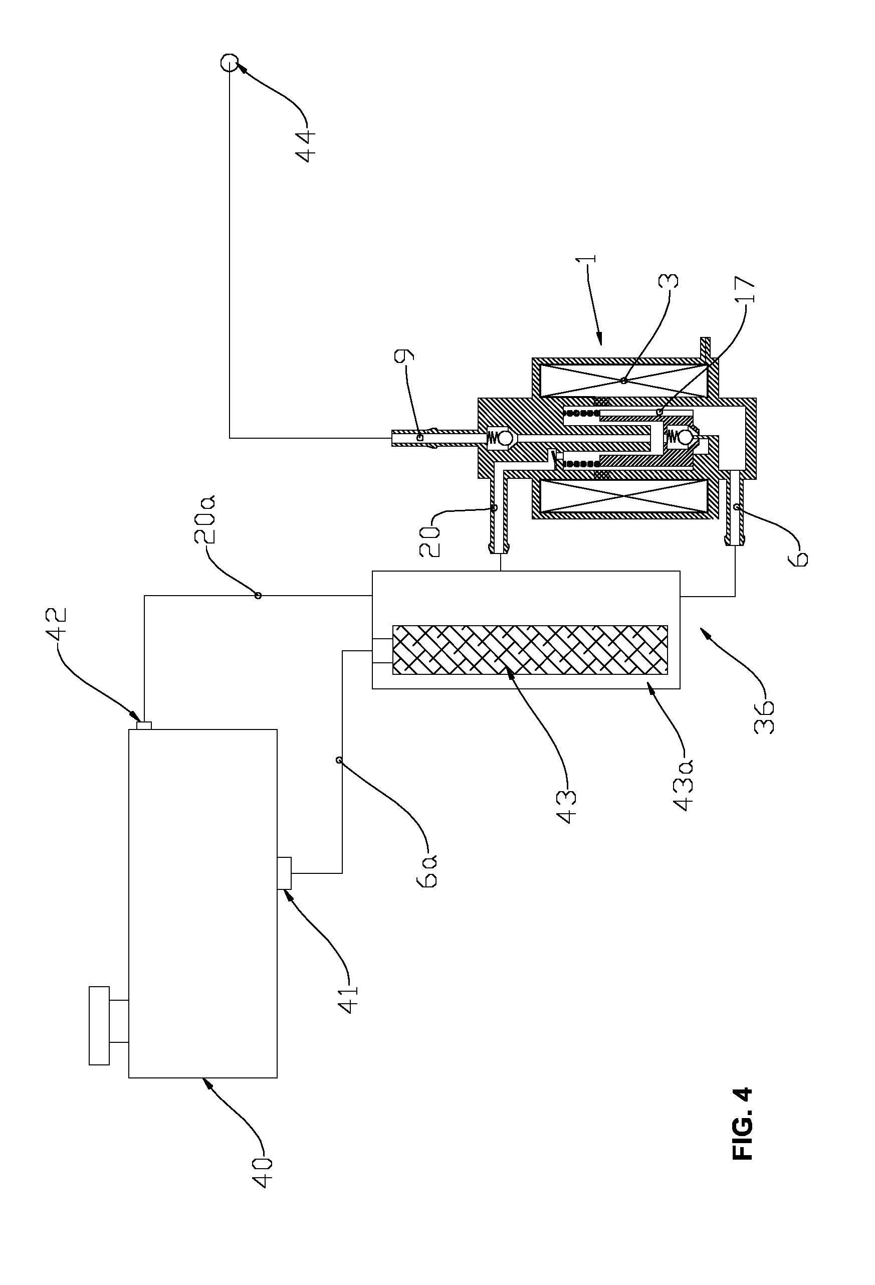
[0017] FIG. 4 is a schematic diagram of a fuel injection application example of a pulse-coupled pump in the invention.
DETAILED DESCRIPTION
[0018] FIG. 1 is a schematic diagram of a pulse-coupled pump according to a first embodiment of the invention. The pulse-coupled pump 1 includes a pump body la and a low-pressure pump 2, a high-pressure pump 12, a solenoid 3, a reset spring 14, a liquid inlet passage 6, an exhaust passage 20, and a liquid delivery passage 9.
[0019] The low-pressure pump 2 includes an armature 17, an armature sleeve 16 and a rectifying valve 21. The armature 16, located in the armature sleeve 16, can move relative to the armature sleeve 16. The armature 17, located in the armature sleeve 16, has a motion relative to the armature sleeve 16. The armature 17 and the armature sleeve 16 are made of permeability magnetic materials. The armature sleeve 16 is embedded with a non-magnetic magnetic gap 15, and the front end of the armature 17 is located near the magnetic gap 15. The rectifying valve 21 is a pressure-opened ball valve, including a rectifying valve 18, a rectifying valve spring 19, a rectifying valve seat 8. When the liquid pressure of the low-pressure pump 2 is higher than the spring force of the rectifying valve spring 19, the rectifying valve 21 is opened, and the liquid and the gas produced are delivered to the exhaust passage 20.
[0020] The high-pressure pump 12 includes a plunger 13, a sleeve 5, an inlet valve 4 and a delivery valve 10. The plunger 13 is connected to the armature 17 in a synchronous motion way. The sleeve 5 includes a central sleeve hole 5b and a side-through hole 5a that connects to the sleeve hole 5b and the low-pressure pump 2. The surface 13a of the plunger 13 is closely matched with the sleeve hole 5b to slide relatively each other, to achieve liquid delivery. The inlet valve 4 is a slide valve formed by the surface 13a of the plunger 13 and the side-through hole 5a. The delivery valve 10 is a one-way ball valve which is opened by pressure and includes a delivery valve 7, a delivery valve spring 8 and a delivery valve seat 11. When the liquid pressure in the high-pressure pump 12 is higher than the spring force of the delivery valve spring 8, the delivery valve 10 is opened, and the liquid enters the liquid delivery passage 9.
[0021] The reset spring 14 acts between the armature 17 and the pump body la, with the action of the magnetic force of the solenoid 3 and the spring force of the reset spring 14, the armature 17 and the plunger 13 reciprocate, to form two-way pulsating liquid in the low-pressure pump 2. The two-way pulsating liquid forms a directional flow through the rectifying valve 21; at the same time, high pressure output of liquid is achieved in the high-pressure pump 12.
[0022] The working process of the pulse-coupled pump is described as follows.
[0023] Liquid enters to the low-pressure pump 2 from the liquid inlet passage 6, then enters to the high-pressure pump 12 through inlet valve 4, filled with the pump body. When the solenoid 3 is energized, the armature 17 drives the plunger 13 into the pressure stroke by the electromagnetic force, and the inlet valve 4 is closed when the surface 13a of the plunger 13 completely shields the side through hole 5a. The plunger 13 continues to move, and the liquid pressure in the high-pressure pump 12 continues to rise. When the pre-set opening pressure of the delivery valve 10 is overcome, the delivery valve 10 is opened, and the high pressure liquid is delivered through the liquid delivery passage 9. During the process, with the movement of armature 17, the liquid pressure in the low-pressure pump 2 is increased, the rectifying valve 21 is opened, and the liquid and gas herein enter the exhaust passage 20 through the rectifying valve 21. When the solenoid 3 is powered off, the armature 17 drives the plunger 13 to return under the spring force of the reset spring 14, the liquid pressure in the high-pressure pump 12 is decreased and the delivery valve 10 is closed. The plunger 13 is opened when moving to the side through hole 5a and the low-pressure pump 2 is connected with the sleeve hole 5b again. Due to the differential pressure, the liquid is rapidly fed into the high-pressure pump 12. During this process, the liquid pressure in the low-pressure pump 2 is dropped and the rectifying valve 21 is closed, to block the discharged bubbles and prevent bubbles from entering the high-pressure pump 12.
[0024] The liquid output of the pulse-coupled pump 1 is determined by the driving force exerted by the solenoid 3.
[0025] FIG. 2 shows a schematic diagram of a pulse-coupled pump according to a second embodiment of the present invention. The first difference between the structure of this embodiment and that of the first embodiment is that: the pulse-coupled pump provided in the invention is a sleeve mobile-type constant delivery pump, and its liquid injection flow is determined by the geometric size of metering pump. The pulse-coupled pump includes a rear limiter and a front limiter, and the solenoid device provides the electromagnetic force required for armature to reach the front limiter. The armature is connected to the sleeve in a synchronized motion way, the armature and sleeve reciprocate fixedly between the rear limiter and the front limiter, resulting in a corresponding change in the volume of the low-pressure pump and the high-pressure pump and the discharge of bubbles and return liquid and liquid injection. The second difference between the structure in the embodiment and that of the first embodiment is that: the rectifying valve is a diaphragm valve including a diaphragm valve body. Only when the liquid pressure in the low-pressure pump is increased, the diaphragm valve is opened, making the liquid and exhaust gas flow directionally. The third difference between the structure in the embodiment and that of the first embodiment is that: the inlet valve is a pressure-operated ball valve, including an inlet valve body, an inlet valve spring, an inlet valve seat and an inlet valve limiter. The inlet valve limiter is fixed relative to the pump body. During the release travel, before the armature reaches the rear limiter, the movement of the inlet valve is stopped by the inlet valve limiter, and the inlet valve remains open.
[0026] FIG. 3 shows a schematic diagram of an SCR application example of a pulse-coupled pump provided in the present invention, including a fluid reservoir, a pulse-coupled pump, a gas-liquid mixing chamber, a compressed air source, an atomizing nozzle mounted on an exhaust duct. The output space of the pulse-coupled pump is communicated with a gas-liquid mixing chamber. The compressed air source is communicated with the gas-liquid mixing chamber via the intake passage.
[0027] A pulse-coupled pump of the invention may be a sleeve mobile-type constant delivery pump, including an external circulation flow passage and a gas-liquid separation chamber connected in series to the circulation space. The external circulation flow passage, located outside of the pump body, is connected to the liquid inlet passage and the exhaust passage respectively, so that the external circulation space is connected in parallel with the low-pressure pump in the pump body to form a space for the liquid circulation, and the clean liquid can be recycled to reduce the burden of the filter. The pulse-coupled pump is placed in the bottom of the fluid reservoir. The liquid in the fluid reservoir, due to its dead weight, enters the low-pressure pump from the liquid inlet passage and enters the high-pressure pump from the inlet valve after passing through the filter.
[0028] The working process of the structure in this application example is as follows.
[0029] A liquid in the reservoir tank enters the pulse-coupled pump from the liquid inlet passage after flowing through the filter. The armature is moved towards the front limiter together with the sleeve by the electromagnetic force. When the liquid pressure in the high-pressure pump is greater than the opening pressure of the delivery valve, the delivery valve is opened, the liquid enters the output space and is injected into the gas-liquid mixing chamber at high pressure, which is mixed with the high-pressure air from the compressed air supply and atomized into the exhaust pipe by atomizing nozzle. During the process, the gas and return liquid produced enter the circulation space through the rectifying valve, which is separated in the gas-liquid separation chamber. The gas is exhausted to the upper space of the reservoir tank through the exhaust passage, while the liquid is flowed back to the liquid inlet passage, to start the next injection.
[0030] FIG. 4 shows a schematic diagram of a fuel injection application example of a pulse-coupled pump provided in the present invention, including a fluid reservoir and a pulse-coupled pump. The fluid reservoir includes an exhaust port at the top and a liquid outlet located at the bottom. The exhaust passage is connected to the exhaust port via the exhaust pipe. The liquid inlet passage is connected to the liquid outlet of the fluid reservoir by means of a liquid supply pipe. The liquid in the fluid reservoir is filtered through the filter and flows from the liquid outlet and the liquid supply pipe into the space where the liquid inside the pulse pump can reach. For the return liquid or fuel vapor produced during the working of pulse-coupled pump, after separated by the circulating space, the liquid part flows back to the liquid inlet passage, and the gas part enters the top of the space inside the fluid reservoir through the exhaust passage, the return pipe and the exhaust port.
[0031] A pulse-coupled pump of the invention may be a solenoid-metering pump, and its injection flow is determined by the driving force exerted by the solenoid. The pulse coupling portion includes an external circulating space and a liquid feed filter that connects to the fluid passage valve. The filter includes a gas-liquid separation chamber and one external circulating space is connected to the exhaust passage, and the other external circulating space is introduced to the clean space of the filter.
[0032] While embodiments of the invention have been illustrated with a limited number of examples. One skilled in the art would appreciate that other modifications and variations are possible. Therefore, other technical solutions based on the essence of the invention shall fall within the scope of the invention.
* * * * *
D00000
D00001
D00002
D00003
D00004
XML
uspto.report is an independent third-party trademark research tool that is not affiliated, endorsed, or sponsored by the United States Patent and Trademark Office (USPTO) or any other governmental organization. The information provided by uspto.report is based on publicly available data at the time of writing and is intended for informational purposes only.
While we strive to provide accurate and up-to-date information, we do not guarantee the accuracy, completeness, reliability, or suitability of the information displayed on this site. The use of this site is at your own risk. Any reliance you place on such information is therefore strictly at your own risk.
All official trademark data, including owner information, should be verified by visiting the official USPTO website at www.uspto.gov. This site is not intended to replace professional legal advice and should not be used as a substitute for consulting with a legal professional who is knowledgeable about trademark law.