Method Of Treating A Steel
DENEUX; Valentine ; et al.
U.S. patent application number 16/162903 was filed with the patent office on 2019-04-18 for method of treating a steel. The applicant listed for this patent is SAFRAN LANDING SYSTEMS. Invention is credited to Nicolas BINOT, Valentine DENEUX.
| Application Number | 20190112680 16/162903 |
| Document ID | / |
| Family ID | 61132537 |
| Filed Date | 2019-04-18 |


| United States Patent Application | 20190112680 |
| Kind Code | A1 |
| DENEUX; Valentine ; et al. | April 18, 2019 |
METHOD OF TREATING A STEEL
Abstract
A method of treating a steel including, in percentages by weight: 0.2% to 0.33% carbon, 4% to 8% cobalt, 7% to 11% nickel, 0.8% to 3% chromium, 0.5% to 2.5% molybdenum, 0.5% to 5.9% tungsten, 0.05% to 0.2% vanadium, and not more than 0.02% titanium, the balance being constituted by iron and inevitable impurities, the method including subjecting the steel to solutionizing heat treatment at a temperature from 950.degree. C. to 1100.degree. C.; then subjecting the steel to quenching treatment; then placing the steel in a cryogenic enclosure; cooling the inside of the cryogenic chamber in which the steel is present to a treatment temperature less than or equal to -73.degree. C.; and subjecting the steel to cryogenic treatment while the treatment temperature is maintained inside the enclosure, the time duration between the end of the quenching treatment and the beginning of the cryogenic treatment being less than or equal to 4 hours.
| Inventors: | DENEUX; Valentine; (LASSEUBE, FR) ; BINOT; Nicolas; (ARAUX, FR) | ||||||||||
| Applicant: |
|
||||||||||
|---|---|---|---|---|---|---|---|---|---|---|---|
| Family ID: | 61132537 | ||||||||||
| Appl. No.: | 16/162903 | ||||||||||
| Filed: | October 17, 2018 |
| Current U.S. Class: | 1/1 |
| Current CPC Class: | C21D 1/18 20130101; C22C 38/44 20130101; C21D 6/02 20130101; C22C 38/46 20130101; C21D 6/007 20130101; C22C 38/50 20130101; C21D 6/04 20130101; C22C 38/52 20130101; C21D 6/004 20130101 |
| International Class: | C21D 6/00 20060101 C21D006/00; C21D 6/04 20060101 C21D006/04; C21D 1/18 20060101 C21D001/18 |
Foreign Application Data
| Date | Code | Application Number |
|---|---|---|
| Oct 18, 2017 | FR | 1759760 |
Claims
1. A method of treating a steel comprising, in percentages by weight: 0.2% to 0.33% carbon, 4% to 8% cobalt, 7% to 11% nickel, 0.8% to 3% chromium, 0.5% to 2. 5% molybdenum, 0.5% to 5.9% tungsten, 0.05% to 0.2% vanadium, and not more than 0.02% titanium, the balance being constituted by iron and inevitable impurities, the method comprising: subjecting the steel to solutionizing heat treatment at a temperature lying in the range 950.degree. C. to 1100.degree. C.; subjecting the steel to quenching treatment, performed after the solutionizing heat treatment; placing the steel in a cryogenic enclosure after the quenching treatment; cooling the inside of the cryogenic chamber in which the steel is present, the cooling being taken down to a treatment temperature less than or equal to -73.degree. C.; and subjecting the steel to cryogenic treatment while the treatment temperature is maintained inside the enclosure, the time duration between the end of the quenching treatment and the beginning of the cryogenic treatment being less than or equal to 4 hours.
2. The method according to claim 1, wherein the time duration between the end of the quenching treatment and the beginning of the cryogenic treatment is less than or equal to 2 hours.
3. The method according to claim 2, wherein the time duration between the end of the quenching treatment and the beginning of the cryogenic treatment is less than or equal to 1 hour.
4. The method according to claim 1, wherein the duration of the cryogenic treatment is greater than or equal to 1 hour.
5. The method according to claim 1, further comprising subjecting the steel to tempering treatment performed after the cryogenic treatment.
6. The method according to claim 1, wherein the treated steel constitutes an aircraft landing gear part.
7. The method according to claim 1, wherein the steel constitutes a part of weight greater than or equal to 10 kg.
8. The method according to claim 1, wherein, during the quenching treatment, the steel is cooled to an end-of-quenching temperature that is less than or equal to 71.degree. C.
Description
CROSS REFERENCE TO RELATED APPLICATIONS
[0001] This application claims priority to French Patent Application No. 1759760, filed Oct. 18, 2017, the entire content of which is incorporated herein by reference in its entirety.
FIELD
[0002] The present invention relates to a method of treating a steel, the method including in particular cryogenic treatment, the steel possibly being for making aircraft landing gear parts.
BACKGROUND
[0003] Patent U.S. Pat. No. 9,051,635 discloses a steel presenting good mechanical properties associated with good stress-corrosion resistance.
[0004] That steel comprising, in percentages by weight, 0.2% to 0.33% carbon, 4% to 8% cobalt, 7% to 11% nickel, 0.8% to 3% chromium, 0.5% to 2.5% molybdenum, 0.5% to 5.9% tungsten, 0.05% to 0.2% vanadium, and not more than 0.02% titanium, the balance being constituted by iron and inevitable impurities, is--in the above-mentioned patent--treated by the following succession of steps, without specifying the time durations between each of the steps: steel solutionizing heat treatment, quenching treatment, immersion in liquid nitrogen, and tempering treatment.
[0005] Such a steel constitutes a material that is of interest for making aircraft landing gear parts, in particular.
[0006] Nevertheless, the inventors have observed that there remains significant dispersion in mechanical properties within batches of steel parts subjected to the treatment disclosed in patent U.S. Pat. No. 9,051,635. It would be desirable to reduce the dispersion of those mechanical properties in order to optimize design curves, and consequently to improve the performance of parts made using that steel, e.g. by making them lighter in weight, by increasing their lifetime, or by increasing the stresses to which they can be exposed.
[0007] Also, the immersion in liquid nitrogen that is performed in Document U.S. Pat. No. 9,051,635 does not constitute a step that is appropriate for treating steel on an industrial scale. Consequently, it remains desirable to have methods of treating that steel that are more compatible with treatment on an industrial scale.
[0008] Also known is the publication by Wang et al. "Austenite layer and precipitation in high Co--Ni maraging steel" (Micron 57 (2014) 112-116) which discloses treatment of a steel whereby, after quenching, the steel is dipped in a cryogenic bath at -73.degree. C.
SUMMARY
[0009] In a first aspect, the invention provides a method of treating a steel comprising, in percentages by weight: 0.2% to 0.33% carbon, 4% to 8% cobalt, 7% to 11% nickel, 0.8% to 3% chromium, 0.5% to 2.5% molybdenum, 0.5% to 5.9% tungsten, 0.05% to 0.2% vanadium, and not more than 0.02% titanium, the balance being constituted by iron and inevitable impurities, the method comprising at least:
[0010] subjecting the steel to solutionizing heat treatment at a temperature lying in the range 950.degree. C. to 1100.degree. C.;
[0011] subjecting the steel to quenching treatment, performed after the solutionizing heat treatment;
[0012] placing the steel in a cryogenic enclosure after the quenching treatment;
[0013] cooling the inside of the cryogenic chamber in which the steel is present, the cooling being taken down to a treatment temperature less than or equal to -73.degree. C.; and
[0014] subjecting the steel to cryogenic treatment while the treatment temperature is maintained inside the enclosure, the time duration between the end of the quenching treatment and the beginning of the cryogenic treatment being less than or equal to 4 hours.
[0015] In particular, the invention is remarkable in that the time duration between the end of the quenching treatment and the beginning of the cryogenic treatment is limited.
[0016] In recent studies, the inventors have observed that the residual austenite content can vary a little within a batch of parts made of the above-described steel that has been subjected to cryogenic treatment. Nevertheless, this variation, even when small, has a significant influence on the dispersion of mechanical properties within the batch of treated parts. It has been possible to identify the small variations in the residual austenite content by using particular measurement techniques that are sufficiently accurate (synchrotron X-ray diffraction and sigmameter). Once the inventors had identified the origin of the dispersion in mechanical properties, they studied the influence of conditions for reaching the cryogenic treatment temperature, and they found that the time duration between the end of quenching and the beginning of the cryogenic treatment had an influence on the residual austenite content. Thus, by limiting this duration, as described above, the invention serves beneficially to obtain better control over the residual austenite content obtained in the treated steel, and consequently to reduce the dispersion in its mechanical properties. Also, the inventors have observed that by limiting this duration, it is beneficially possible to improve the stress-corrosion resistance of the steel. By performing the cryogenic treatment in a cryogenic enclosure that is cooled after being loaded with the steel, it is beneficially possible to make the method compatible with treatment on an industrial scale. Also, the invention causes the cryogenic enclosure in which the steel is placed to cool progressively, which also contributes to controlling the residual austenite content compared with the situation in which the steel is dipped directly into a cryogenic bar. Specifically, such dipping results in an undesirable phenomenon of film boiling, which prevents proper control over the cooling, and which has the consequence of not enabling the residual austenite content to be properly controlled.
[0017] In an embodiment, the time duration between the end of the quenching treatment and the beginning of the cryogenic treatment is less than or equal to 2 hours, an in an embodiment less than or equal to 1 hour.
[0018] Imposing such a time duration between quenching and the beginning of cryogenic treatment serves beneficially to further reduce the dispersion in mechanical properties that is obtained for the treated steel.
[0019] In an embodiment, the duration of the cryogenic treatment is greater than or equal to 1 hour.
[0020] In an embodiment, the method further comprises subjecting the steel to tempering treatment performed after the cryogenic treatment.
[0021] In an embodiment, the treated steel constitutes an aircraft landing gear part. By way of example, the part may be an axle, a rocker beam, or a portion of the rocker beam, such as its pivot axis.
[0022] In an embodiment, the steel constitutes a part of weight greater than or equal to 10 kilograms (kg). The weight of the part may be greater than or equal to 40 kg, e.g. greater than or equal to 100 kg.
[0023] The invention is particularly beneficial when treating a part of significant weight, and thus of considerable size, in so far as the above-mentioned undesirable phenomenon of film boiling occurs regardless of the size of the part, but is more marked with increasing size of the part.
[0024] In an embodiment, during the quenching treatment, the steel is cooled to an end-of-quenching temperature that is less than or equal to 71.degree. C.
[0025] Using a low end-of-quenching temperature contributes beneficially to still further reducing the residual austenite content.
BRIEF DESCRIPTION OF THE DRAWINGS
[0026] Other characteristics and benefits of the invention appear from the following description, given by way of nonlimiting example and with reference to the accompanying figures, in which:
[0027] FIG. 1 is a diagram showing how the temperature imposed on the steel varies in an example of the treatment method of an embodiment of the invention; and
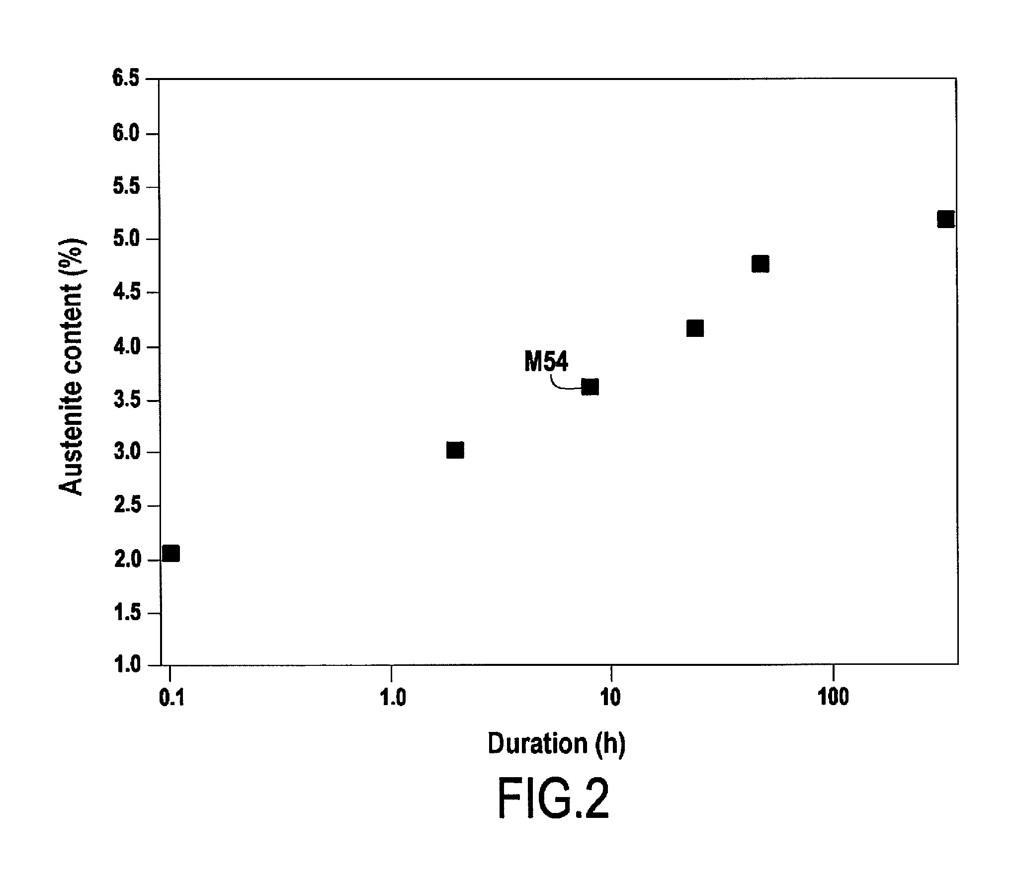
[0028] FIG. 2 shows the result of a comparative test revealing the influence on the residual austenite content of the time duration between the end of the quenching treatment and the beginning of the cryogenic treatment.
DETAILED DESCRIPTION
[0029] In percentages by weight, the treated steel comprises: 0.2% to 0.33% carbon, 4% to 8% cobalt, 7% to 11% nickel, 0.8% to 3% chromium, 0.5% to 2.5% molybdenum, 0.5% to 5.9% tungsten, 0.05% to 0.2% vanadium, and no more than 0.02% titanium, the balance being constituted by iron and inevitable impurities.
[0030] In an embodiment, and in percentages by weight, the treated steel comprises: 0.25% to 0.31% carbon, 6.8% to 8% cobalt, 9.3% to 10.5% nickel, 0.8% to 2.6% chromium, 0.9% to 2.1% molybdenum, 0.7% to 2% tungsten, 0.05% to 0.12% vanadium, and no more than 0.015% titanium, the balance being constituted by iron and inevitable impurities.
[0031] In an embodiment, and in percentages by weight, the treated steel comprises: 0.29% to 0.31% carbon, 6.8% to 7.2% cobalt, 9.8% to 10.2% nickel, 0.8% to 2.6% chromium, 0.9% to 2.1% molybdenum, 0.7% to 1.4% tungsten, 0.05% to 0.12% vanadium, and no more than 0.015% titanium, the balance being constituted by iron and inevitable impurities.
[0032] The method begins with a temperature rise ramp (step E1) up to a temperature Ts, lying in the range 950.degree. C. to 1100.degree. C.
[0033] Thereafter the temperature Ts is maintained in order to subject the steel to solutionizing heat treatment (step E2). The duration of the steel solutionizing heat treatment E2 may be greater than or equal to 1 hour, e.g. lying in the range 1 hour to 2 hours.
[0034] The steel is then subjected to quenching treatment (step E3) at the end of the solutionizing treatment E2. The quenching treatment E3 consists in cooling the steel rapidly by immersing it in a cooling fluid such as water or oil. During the quenching treatment E3, the steel is cooled to an end-of-quenching temperature Ta. In the example shown, this end-of-quenching temperatures Ta is equal to ambient temperature (20.degree. C.), but it would not go beyond the ambit of the invention for it to be different from ambient temperature, e.g. higher than ambient temperature. The end-of-quenching temperature Ta may be less than or equal to 71.degree. C., and in an embodiment less than or equal to 50.degree. C. In particular, the end-of-quenching temperature Ta may lie in the range 16.degree. C. to 71.degree. C. At the end of the quenching treatment E3, the steel is no longer being cooled by exchanging heat with the above-mentioned cooling fluid used for quenching. At that moment, the temperature of the steel is equal to the end-of-quenching temperature Ta.
[0035] Where necessary, after quenching E3 and before placing the steel in the cryogenic enclosure, a first intermediate step (step E4) may be performed during which the steel is maintained in an environment at ambient temperature Ta. In a variant, this first intermediate step E4 may be omitted, and the steel may be placed directly in the cryogenic enclosure after the quenching treatment E3. Naturally, when it is performed, this first intermediate step E4 is of limited duration so that the time duration between the end of the quenching treatment E3 and the beginning of the cryogenic treatment also remains limited, as mentioned above.
[0036] Once the steel has been placed in the cryogenic enclosure, the inside of the enclosure is then cooled down (step E5).
[0037] This cooling comprises a temperature lowering ramp down to the treatment temperature Tc, which is less than or equal to -73.degree. C. The rate of cooling imposed during this temperature lowering ramp may be greater than or equal to 0.5.degree. C. per minute (C.degree./min), e.g. greater than or equal to 1.5.degree. C./min, or indeed greater than or equal to 2.5.degree. C./min, or indeed greater than or equal to 5.degree. C./min. This rate of cooling may also be less than or equal to 4.degree. C./min. This imposed rate of cooling may be substantially constant. It would not go beyond the ambit of the invention for the rate of cooling to vary during the cooling step E5, so the cooling step E5 could thus comprise a first temperature drop at a first rate of cooling, followed by a second temperature drop at a second rate of cooling different from the first, e.g. slower than the first.
[0038] As mentioned above, an aspect of the invention limits the time duration between the end of the quenching treatment E3, corresponding to the moment when the end-of-quenching temperature Ta is reached, and the beginning of the cryogenic treatment E6, corresponding to the moment when the treatment temperature Tc is reached. This duration corresponds to the time duration after the end of quenching E3 during which the steel is at a temperature higher than the treatment temperature Tc. Limiting this duration serves to limit the residual austenite content. FIG. 2 shows a result of a comparative test performed on a Ferrium.RTM. M54 steel while using an end-of-quenching temperature Ta of 20.degree. C. and a treatment temperature Tc of -73.degree. C. In that test, the time duration between the end of the quenching treatment and the beginning of the cryogenic treatment was varied. It can be seen that the longer that time duration, the greater the increase in the residual austenite content in the steel. The inventors have also carried out a comparative test in order to determine the influence on the stress-corrosion resistance of the steel of the time duration between the end of the quenching treatment and the beginning of the cryogenic treatment. In that test, the stress-corrosion resistance of the steel was measured as follows: an initial crack was made in the test piece, which was wetted with a solution of NaCl, and then a constant stress was imposed on the sample, and at the end of 1000 hours (h), the K1SCC was determined. At the end of 1000 h, the test piece was broken in static manner, thereby enabling its K1SCC to be determined from the size of the initial crack and the value of the load. K1SCC is a parameter known to the person skilled in the art for quantifying stress-corrosion resistance. The test that was performed showed that the stress-corrosion resistance of the steel was significantly better when the steel had been subjected to treatment in which the time duration between the end of the quenching treatment and the beginning of the cryogenic treatment was limited to 2 hours, compared with the situation not in the invention when the duration was 8 hours.
[0039] The installation suitable for performing the method is itself known. Such an installation comprises a cryogenic enclosure connected to a tank of cooling fluid together with a control system configured to control the rate at which the cooling fluid is introduced into the inside of the enclosure, and the rate at which it is discharged out therefrom. The cooling fluid may be introduced into the inside of the enclosure while in the gaseous state. Under such circumstances, the cooling fluid may be vaporized outside the enclosure and then the cooling fluid in the gaseous state as generated in that way can be introduced into the inside of the enclosure through at least one injection port. As a result of controlling the introduction and discharge flow rates, it is possible to obtain the desired rate of cooling, which contributes to obtaining the desired duration between the end of quenching E3 and the beginning of the cryogenic treatment E6. This control over the introduction and discharge flow rates also makes it possible to maintain the treatment temperatures Tc during the cryogenic treatment. As an example of a cryogenic installation that is suitable, mention may be made of the liquid nitrogen type fluid Linde Gas VF TES installation.
[0040] There is then a temperature stabilization dwell, during which the treatment temperatures Tc is maintained in order to perform the cryogenic treatment of the steel (step E6). The duration of the cryogenic treatment E6 is predetermined, and may be greater than or equal to 1 hour, e.g. lying in the range 1 to 2 hours.
[0041] Once the cryogenic treatment E6 has been performed, the temperature may be raised progressively up to ambient temperature Ta (step E7).
[0042] If so desired, it is then possible to perform a second intermediate step E8 during which the steel is maintained in an environment at ambient temperature Ta.
[0043] Thereafter, a temperature raising ramp may be performed (step E9) up to a tempering temperature Tr, e.g. lying in the range 465.degree. C. to 550.degree. C.
[0044] A temperature stabilization dwell at the tempering temperature Tr is then carried out in order to perform the tempering heat treatment (step E10). The duration of the tempering heat treatment may be greater than or equal to 4 hours, for example it may lie in the range 4 hours to 32 hours.
[0045] The steel may then be cooled, e.g. by maintaining it in an environment at ambient temperature.
[0046] The term "lying in the range . . . to . . . " should be understood as including the bounds.
* * * * *
D00000
D00001
D00002
XML
uspto.report is an independent third-party trademark research tool that is not affiliated, endorsed, or sponsored by the United States Patent and Trademark Office (USPTO) or any other governmental organization. The information provided by uspto.report is based on publicly available data at the time of writing and is intended for informational purposes only.
While we strive to provide accurate and up-to-date information, we do not guarantee the accuracy, completeness, reliability, or suitability of the information displayed on this site. The use of this site is at your own risk. Any reliance you place on such information is therefore strictly at your own risk.
All official trademark data, including owner information, should be verified by visiting the official USPTO website at www.uspto.gov. This site is not intended to replace professional legal advice and should not be used as a substitute for consulting with a legal professional who is knowledgeable about trademark law.