Cooling Apparatus For Carbonized Biomass
HAYASHI; Shigeya ; et al.
U.S. patent application number 16/090515 was filed with the patent office on 2019-04-18 for cooling apparatus for carbonized biomass. This patent application is currently assigned to UBE INDUSTRIES, LTD.. The applicant listed for this patent is UBE INDUSTRIES, LTD.. Invention is credited to Naohide FUJIMOTO, Shigeya HAYASHI, Daisuke MAKI, Tatsumi TANO.
| Application Number | 20190112530 16/090515 |
| Document ID | / |
| Family ID | 60000491 |
| Filed Date | 2019-04-18 |


View All Diagrams
| United States Patent Application | 20190112530 |
| Kind Code | A1 |
| HAYASHI; Shigeya ; et al. | April 18, 2019 |
COOLING APPARATUS FOR CARBONIZED BIOMASS
Abstract
An apparatus including a carbonizing furnace for obtaining a carbonized biomass by carbonizing a molded biomass and classification means disposed at the downstream side of the carbonizing furnace for classifying the carbonized biomass, and cooling means disposed at the downstream side of the classification means for cooling the classified carbonized biomass. The molded biomass is obtained by molding pulverized raw biomass and the cooling means cools the carbonized biomass by spraying water.
| Inventors: | HAYASHI; Shigeya; (Ube-shi, JP) ; TANO; Tatsumi; (Ube-shi, JP) ; FUJIMOTO; Naohide; (Ube-shi, JP) ; MAKI; Daisuke; (Ube-shi, JP) | ||||||||||
| Applicant: |
|
||||||||||
|---|---|---|---|---|---|---|---|---|---|---|---|
| Assignee: | UBE INDUSTRIES, LTD. Ube-shi JP |
||||||||||
| Family ID: | 60000491 | ||||||||||
| Appl. No.: | 16/090515 | ||||||||||
| Filed: | April 3, 2017 | ||||||||||
| PCT Filed: | April 3, 2017 | ||||||||||
| PCT NO: | PCT/JP2017/014002 | ||||||||||
| 371 Date: | October 1, 2018 |
| Current U.S. Class: | 1/1 |
| Current CPC Class: | C10L 2200/0469 20130101; C10L 2290/06 20130101; C10L 2290/02 20130101; C10L 2290/18 20130101; C10L 5/442 20130101; C10L 9/086 20130101; Y02E 50/10 20130101; C10B 53/08 20130101; C10L 5/361 20130101; C10B 39/04 20130101; C10B 39/16 20130101; C10B 45/00 20130101; C10B 53/02 20130101; Y02E 50/14 20130101; C10L 2290/32 20130101 |
| International Class: | C10B 39/04 20060101 C10B039/04; C10L 5/44 20060101 C10L005/44; C10B 53/02 20060101 C10B053/02; C10B 53/08 20060101 C10B053/08; C10B 45/00 20060101 C10B045/00; C10B 39/16 20060101 C10B039/16 |
Foreign Application Data
| Date | Code | Application Number |
|---|---|---|
| Apr 6, 2016 | JP | 2016-076234 |
Claims
1. A cooling apparatus for carbonized biomass, comprising: a carbonizing furnace for obtaining carbonized biomass by carbonizing molded biomass, a classification section, disposed at downstream side of the carbonizing furnace, for classifying the carbonized biomass, and a cooler, disposed at downstream side of the classification section, for cooling the classified carbonized biomass, wherein the molded biomass is obtained by molding pulverized raw biomass, and the cooler cools the carbonized biomass by spraying water thereon.
2. The cooling apparatus for carbonized biomass according to claim 1, wherein the cooler comprises a vibration flat plate and a spraying section for spraying water on the flat plate, wherein the flat plate is a metal plate or a resin plate, and the carbonized biomass is transported by vibration.
3. The cooling apparatus for carbonized biomass according to claim 2, further comprising a thermometer for measuring temperature at an outlet of the carbonizing furnace, and a controller for stopping the spraying section if temperature measured by the thermometer is a predetermined value or lower.
4. The cooling apparatus for carbonized biomass according to claim 3, wherein the thermometer can directly measure temperature of the carbonized biomass.
5. The cooling apparatus for carbonized biomass according to claim 1, further comprising a separating section for separating the classification section and the cooler.
Description
TECHNICAL FIELD
[0001] The present invention relates to a cooling apparatus for carbonized biomass.
BACKGROUND ART
[0002] Conventionally, in Patent Document 1, bio coke having an excellent strength is obtained by pressure-molding pulverized biomass while heating it to effect semi-carbonization.
CITATION LIST
Patent Document
Patent Document 1: Patent No. 4088933
SUMMARY OF INVENTION
Technical Problem
[0003] However, in the Patent Document 1, there is a problem that the cooling efficiency is low because the product after molding is cooled in a pressurized state and by natural cooling in the air. Even if water cooling is tried to improve cooling efficiency, the water cooling under pressurized state is difficult, and the water cooling causes disintegration of a part of bio coke which is a molded product of pulverized biomass, which makes handling difficult. In particular, in the unsteady state in which heating is not carried out, there is a risk that the molded bio coke may disintegrate, leading to the clogging in the facility. Alternatively, for simplicity, if cooling is carried out by putting the bio coke into a water tub or the like after the carbonization (heating), collecting process becomes complicated because the biomass solid fuel floats due to its light specific gravity.
[0004] The present invention has been made to solve the above problems and an objective of the present invention is to improve the cooling efficiency of semi-carbonized molded biomass while reducing clogging in a facility.
Solution to Problem
[0005] The present invention comprises a carbonizing furnace for obtaining carbonized biomass by carbonizing molded biomass; classification means, disposed at downstream side of the carbonizing furnace, for classifying the carbonized biomass; and cooling means, disposed at downstream side of the classification means, for cooling the classified carbonized biomass; wherein the molded biomass is obtained by molding pulverized raw biomass, and the cooling means cools the carbonized biomass by spraying water thereon.
Advantageous Effect of Invention
[0006] According to the present invention, there is provided an improvement in the cooling efficiency of semi-carbonized molded biomass while reducing clogging in a facility.
BRIEF DESCRIPTION OF DRAWING
[0007] FIG. 1 is a graph showing COD and pH versus solid temperature of the biomass solid fuels.
[0008] FIG. 2 is a graph showing the correlation of the solid temperature of the heating step to grindability index and pulverizing rate of the obtained biomass solid fuels.
[0009] FIG. 3 is a graph showing a particle size distribution of the biomass solid fuels subjected to disintegration test.
[0010] FIG. 4 is a graph showing the results of a water immersion test (moisture content of the solid) of biomass solid fuels.
[0011] FIG. 5 is a graph showing the solid strength (rotation strength) before and after a water immersion test.
[0012] FIG. 6 is a graph showing the solid strength (mechanical durability) before and after a water immersion test.
[0013] FIG. 7 is a graph showing BET specific surface area of the solid fuels.
[0014] FIG. 8 is a graph showing an average pore diameter of the surface of the solid fuels.
[0015] FIG. 9 is a graph showing a total pore volume of the surface of the solid fuels.
[0016] FIG. 10 is a graph showing a yield of the biomass solid fuels.
[0017] FIG. 11 is a graph showing a spontaneous combustion index (SCI) of the biomass solid fuels.
[0018] FIG. 12 is a cross-sectional photograph before immersion in water of Example A-2.
[0019] FIG. 13 is a cross-sectional photograph after immersion in water (2 seconds) of Example A-2.
[0020] FIG. 14 is a cross-sectional photograph after immersion in water (20 seconds) of Example A-2.
[0021] FIG. 15 is a cross-sectional photograph before immersion in water of Comparative Example A.
[0022] FIG. 16 is a cross-sectional photograph after immersion in water (2 seconds) of Comparative Example A.
[0023] FIG. 17 is a cross-sectional photograph after immersion in water (20 seconds) of Comparative Example A.
[0024] FIG. 18 is a diagram showing (estimated) mechanism of the development of solid cross-links in PBT.
[0025] FIG. 19 is a chart showing the results of FT-IR analysis of the outer surface of pellets of the biomass solid fuels.
[0026] FIG. 20 is a chart showing the results of FT-IR analysis of the cross-sectional center of pellets of the biomass solid fuels.
[0027] FIG. 21 is a chart showing the results of FT-IR analysis of acetone extract solution of the biomass solid fuels.
[0028] FIG. 22 is a chart showing the results of FT-IR analysis of the solid of biomass solid fuels after acetone extract.
[0029] FIG. 23 is a chart showing the results of GC-MS analysis of acetone extract solution of the biomass solid fuels.
[0030] FIG. 24 is a photograph showing the shape of a pellet after immersion in physiological saline solution in Example B.
[0031] FIG. 25 is a diagram showing the distribution of sodium before and after immersion in physiological saline in Example B.
[0032] FIG. 26A is a schematic view showing a cooling facility for carbonized biomass.
[0033] FIG. 26B is a schematic view showing another example of the cooling facility for carbonized biomass.
[0034] FIG. 27 is a diagram showing a process flow of the present invention.
[0035] FIG. 28 is a diagram showing a control flow.
DESCRIPTION OF EMBODIMENT
[0036] FIG. 26A is a schematic view of the present invention and FIG. 27 is a process flow. A biomass solid fuel obtained by a fuel manufacturing step 100 in FIG. 27 becomes a product through a classification step 200 and a cooling step 300.
[0037] In the fuel manufacturing step, the biomass solid fuel is manufactured by using known method. Raw biomass is molded in a molding step 120 after a crushing-pulverizing step 110, then the molded biomass is heated by using a kiln 1 in FIG. 26A in a heating step 130. No binding agent such as binder is added in the molding step 120, and the pulverized biomass particles is simply compressed or pressed for molding.
[0038] The unheated molded biomass just after the molding step 120 (White Pellet: referred to as WP below) has a low strength since it is obtained by just pressing and molding pulverized biomass, therefore it tends to disintegrate easily during handling. Further, it expands and disintegrates by absorbing water.
[0039] In the fuel manufacturing step 100 of the present invention, by heating the molded biomass at 150 to 400.degree. C. (low-temperature carbonizing) in heating step 130 (kiln 1), a biomass solid fuel (Pelletizing Before Torrefaction: referred to as PBT below) having high-strength and water-resistance is manufactured, while keeping a shape as a molded product. The details of the fuel manufacturing step 100 will be described later.
[0040] The classification step 200 and the cooling step 300 are carried out by using a vibrating conveyer 2 shown in FIG. 26A. The vibrating conveyer 2 is separated into two sections by a separating plate 24, in which one of the sections is a classification section 21 and the other is a cooling section 22. The PBT discharged from the kiln 1 is transported by vibration of a flat plate 22b and by being pushed by the PBT which is continuously supplied from the kiln 1. The PBT is discharged as a product through the classification section 21 and the cooling section 22. Although the vibrating conveyer 2 in FIG. 26A is inclined, horizontal one that is not inclined can be used.
[0041] Classification of PBT and fine powder (classification step 200) is carried out by vibrating PBT on a sieve 21a in the classification section 21. Opening size of the sieve 21a may be changed accordingly to the desired value. The PBT disintegrated during manufacturing or the PBT smaller than the predetermined size fall down from the sieve 21a and are treated in other process. The PBT remaining on the sieve is transported to the cooling section 22.
[0042] The cooling section 22 has a spraying section 22a and a vibration flat plate 22b, wherein the spraying section 22a is configured to spray water on the flat plate 22b. The PBT on the flat plate 22b is cooled by water spraying (cooling step 300), and then discharged as a product. It is noted that cooling may be implemented by spraying water only, or by using air cooling together by providing air nozzle or the like in addition to the spraying section 22a. Moreover, a two-fluid spray nozzle for air and water may be used.
[0043] The flat plate 22b is a smooth plate that has no hole and no concave-convex, and a metal plate or a resin plate is used for it. Employment of a smooth plate allows the PBT to slide easily in the cooling section 22, resulting in smooth transportation in the cooling section 22.
[0044] Since the classification section 21 and the cooling section 22 is separated by the separating plate 24, it is possible to prevent splayed water within the cooling section 22 from entering into the classification section 21. Accordingly, water absorption by fine powder which has been classified in the classification section 21 is prevented and thus, clogging in the classification section 21 can be reduced.
[0045] A thermometer 11 is disposed at an outlet of the kiln 1 and a control section 30 is configured to perform spraying water and stopping water spraying based on the measured temperature. It is noted that the thermometer 11 may be disposed at other position as long as it is disposed at such a position that allows the thermometer to measure a temperature of the kiln 1.
[0046] In the present invention, while PBT having high strength and water-resistance can be obtained by heating WP in the kiln 1, if the temperature of kiln 1 is at a predetermined value or lower, unheated WP or molded biomass that does not have enough strength and water-resistance will be discharged from the kiln 1. If they are fed to a vibrating conveyer 2, since they have poor water-resistance, they will expand and disintegrate after water absorption in the spraying section 22, and cause clogging in the facility.
[0047] Accordingly, if a temperature measured by the thermometer 11 is below a predetermined value, it is judged as a low temperature insufficient for PBT manufacturing and the control section 30 stops spraying water by spraying section 22a. By doing so, even if WP or insufficiently-heated PBT is discharged from the kiln when the temperature of kiln is low, the disintegration at the spraying section 22 is restrained and clogging in the facility can be avoided.
[0048] FIG. 28 is a flowchart of continuing and stopping of spraying water based on temperature, which is carried out by the control section 30. In a step S1, a temperature of the outlet of kiln 1 is measured by the thermometer 11.
[0049] In a step S2, it is judged whether the measured temperature T is a predetermined value a or lower; if YES then spraying water is stopped in a step S3 whereas if NO then spraying water is carried out in a step S4.
[0050] Particularly in a starting-up phase or unsteady state of the kiln 1 or in a low-temperature state, unheated WP or insufficiently-heated molded biomass is discharged from the kiln 1, therefore stopping of water spray prevents the disintegration and clogging in the facility.
[0051] If transportation of the WP in the kiln 1 is stopped when the kiln 1 has stopped and temperature becomes a predetermined value or lower, the WP remains inside of the kiln 1. In that case, a large amount of thermal decomposition gas is generated due to progress of carbonization of WP even at low temperature, which necessitates another complicated process for processing the gas. Furthermore, the excessively carbonized WP is unfavorable for fuel since amount of the remaining volatile component in the WP decreases, and needs to be processed additionally, leading to the increase in additional steps. Accordingly, stopping of transportation in the kiln 1 is not preferable.
[0052] On the other hand, if the supply of WP is stopped at low temperature but transportation in the kiln 1 is continued, non-carbonized WP or insufficiently-heated molded biomass will be discharged. Therefore, even at low temperature, transportion is not stopped so that the generation of a large amount of thermal decomposition gas and excessive carbonization are prevented, and also spraying water on the discharged WP is stopped so that clogging is suppressed.
[0053] It is noted that the thermometer 11 directly measures not an atmosphere temperature of outlet of the kiln 1 but a temperature of PBT at the outlet of the kiln 1. Although in the present invention the PBT (solid fuel) having water-resistance and high-strength is obtained by carbonizing WP at a predetermined temperature or higher, the excessive temperature increase accelerates carbonization more than necessary and reduces a thermal yield, leading to insufficient fuel properties. To keep a maximum thermal yield and obtain water-resistance and strength, accurate temperature control is required; and therefore the temperature of PBT is measured directly to accomplish a high accuracy carbonization. Thermometer 11 may be any type as long as it can directly measure a temperature of PBT at outlet of kiln 1, and a contact type thermometer or a non-contact type thermometer such as infrared radiation may be used.
<Effect>
[0054] (1) An apparatus comprises a kiln 1 (a carbonizing furnace) for obtaining carbonized biomass (PBT) by carbonizing molded biomass, a classification section 21 (classification means), disposed at downstream side of the kiln 1, for classifying the carbonized biomass (PBT), and a cooling section 22 (cooling means), disposed at downstream side of the classification section 21, for cooling the classified carbonized biomass (PBT), wherein the molded biomass is obtained by molding pulverized raw biomass and wherein the cooling section 22 cools the carbonized biomass (PBT) by spraying water.
[0055] If the carbonized biomass is cooled by immersing it in water, handling is difficult because the carbonized biomass floats on water and spreads on the water surface. On the other hand, even in the case of cooling by spraying water, the molded biomass tends to disintegrate to particles again because it is obtained by molding pulverized biomass. Therefore, there is a risk that clogging in a facility may take place because the pulverized biomass absorbs water if water is splayed while no measure is taken. However, clogging can be avoided by carrying out spraying water after the classification of the carbonized biomass. In addition to spraying water, air cooling and water spraying may be used in combination, or a two-fluid nozzle for air and water may be used.
[0056] (2) The cooling section 22 comprises a vibration flat plate 22b (flat plate) and a splaying section 22a for spraying water on the flat plate 22b, wherein the flat plate 22b is a metal plate or a resin plate, and the carbonized biomass (PBT) is transported by vibration.
[0057] Since a part of carbonized biomass (PBT) disintegrates during transportation, the carbonized biomass having small diameter remains in a certain amount even after classification. The smaller the diameter, the more it tends to adhere to each other by spraying water, which makes handling during transportation difficult. Here, if carbonized biomass is cooled on the net in consideration of draining water, the water-sprayed carbonized biomass may be piled up due to the resistance of concave-convex of the net and transportation efficiency may decrease, leading to clogging in the facility. However, efficient transportation can be carried out by using a metal plate or a resin plate having a small sliding resistance with the carbonized biomass so as to reduce the resistance during the transportation.
[0058] (3) Control section 30 (control means) is provided for stopping spraying water by the spraying section 22a if a temperature at the outlet of kiln 1 is at a predetermined value or lower. In unsteady state such as starting-up phase or stopping phase, since the temperature of kiln 1 is equal to a predetermined value or lower (low temperature insufficient for manufacturing PBT), non-carbonized molded biomass or insufficiently-carbonized molded biomass with low-strength or low water-resistance is discharged. They may swell and disintegrate, leading to clogging in the facility. However, clogging can be avoided by stopping spraying water.
[0059] (4) Thermometer 11 can directly measure the temperature of carbonized biomass (PBT). Although water-resistant and high-strength PBT (solid fuel) can be obtained by carbonizing WP at a predetermined temperature or higher, excessive carbonization deteriorates thermal yield. Therefore, by directly measuring the temperature of PBT, highly accurate carbonization can be carried out, allowing the production of the product having water-resistance and high-strength while ensuring thermal yield.
[0060] (5) Separating section 24 for separating the classification section 21 and the cooling section 22 is provided. By separating these sections, it is possible to prevent the sprayed water from entering into the classification section 22, and thus, piling up of the product and clogging during classification are suppressed.
[0061] Instead of the vibrating conveyor 2 in the above-mentioned embodiment, a classification step and a cooling step may be carried out using a system as shown in FIG. 26B. The system 402 includes a vibrating sieve apparatus 403A and a cooling vibrating conveyor 403B. The vibrating sieve apparatus 403A and the cooling vibrating conveyor 403B are configured to have separate bodies. The vibrating sieve apparatus 403A is disposed at the upstream side of a transport direction of the PBT, and the cooling vibrating conveyor 403B is disposed at the downstream side. The description for the functions and structures common to the configuration in FIG. 26A will be omitted to avoid redundant description.
[0062] The vibrating sieve apparatus 403A has a classifying section 421 provided with a sieve 421a. As with the configuration of FIG. 26A, PBT is supplied from the rotary kiln (not shown in FIG. 26B) onto the sieve 421a. The PBT is transported while being vibrated on the sieve 421a, whereby classification (classification step) of PBT and fine powder is carried out. Although the vibrating sieve apparatus 403A is inclined, a horizontal one that is not inclined can be used.
[0063] Regarding the opening size of the sieve 421a, as mentioned in the above embodiment, it may be changed appropriately according to a desired value. Those disintegrated during manufacturing or small PBT that do not reach a predetermined size fall under the sieve 421a and are processed separately. The PBT remaining on the sieve 421a is discharged from an outlet 421b of the vibrating sieve apparatus 403A.
[0064] The cooling vibrating conveyor 403B has a cooling section 422 provided with a water spray section 422a and a vibration flat plate 422b and the like, and the PBT from the vibrating sieve apparatus 403A is supplied onto the flat plate 422b. Although not shown, the cooling vibrating conveyor 403B is also provided with a control section for controlling the operation of the water spray section 422a and the like, as in the configuration of FIG. 26A. As an example, the flat plate 422b is a smooth plate without holes and concave-convex, and a metal plate or a resin plate is used. Employment of a smooth plate allows the PBT to slide easily, enabling smooth transportation. Although the cooling vibrating apparatus 403B is inclined, a horizontal one that is not inclined can be used.
[0065] Also in this example, cooling may be carried out by water spraying only, or it may be carried out by using air cooling in combination with water spraying. Spray nozzle may be a two-fluid nozzle for air and water. Further, similarly to the above-mentioned embodiment, it is preferable in one embodiment that the water spraying by water spray section 422a may be controlled so as to stop water spraying when the temperature measured by the thermometer 11 of the kiln 1 (see FIG. 26A) is below a predetermined value. It should be noted that the technical matters disclosed in FIG. 26B can be combined with or replaced with the matters disclosed in other embodiments, without departing from the scope of the present invention.
[0066] A method of manufacturing the biomass solid fuel (PBT) produced in the above-described fuel manufacturing step 100 will be described in detail as follows.
[Manufacturing of Biomass Solid Fuel (PBT) in Fuel Manufacturing Step]
[0067] The biomass solid fuel is a molded solid product obtained by the steps including a molding step of compressing and molding biomass that has been crushed and pulverized to a state of debris or powder into biomass blocks, and a heating step of heating the biomass blocks. The molded and heated solid product is used as a fuel (corresponding to PBT mentioned below). Since the biomass solid fuel does not require a step of steam explosion and the use of a binder, the cost increase is suppressed. In the present specification, the biomass blocks obtained by molding process and before the heating step are also referred to as "unheated biomass blocks". The unheated biomass blocks correspond to the WP as mentioned above.
[0068] Biomass as a raw material may be any wood-based and herbaceous material, and tree species and parts thereof or the like are not particularly limited, but examples include douglas fir, hemlock, cedar, cypress, European red pine, almond old tree, almond shell, acacia xylem part, acacia bark, walnut shell, sago palm, EFB (empty fruit bunch that is a residue of palm oil processing), meranti, rubber tree and the like. These may be used alone or in a mixture of two or more of these.
[0069] In the molding process, the biomass blocks are formed by using known molding techniques. The biomass blocks are preferably in a form of pellet or briquette, and the size thereof is arbitrary. In the heating step, the molded biomass blocks are heated.
[0070] In a biomass solid fuel obtained after the heating step, the COD (Chemical Oxygen Demand) of an immersion water used for water immersion is preferably 3,000 ppm or less. In addition, COD ratio represented by (COD of biomass solid fuel after the heating step/COD of unheated biomass solid fuel) of the biomass solid fuel is preferably 0.98 or less. Here, the COD (Chemical Oxygen Demand) of an immersion water used for water immersion of a biomass solid fuel (simply, may be referred to as "COD") means a COD value assayed in accordance with JIS K0102(2010)-17 for a sample of immersion water for COD determination prepared in accordance with Japan Environment Agency Announcement No. 13 "(A) a method for detecting a metal or the like contained in an industrial waste", 1973.
[0071] The biomass solid fuel obtained after the heating step has a Hardgrove grindability index (HOT) in accordance with JIS M 8801 of preferably 15 or more and 60 or less, and more preferably 20 or more and 60 or less. Further, BET specific surface area thereof is 0.15 to 0.8 m.sup.2/g, and more preferably 0.15 to 0.7 m.sup.2/g. It is preferable that the equilibrium moisture content after immersion in water is 15 to 65 wt %, and more preferably 15 to 60 wt %.
[0072] The biomass solid fuel of the present invention has a fuel ratio (fixed carbon/volatile matter) of 0.2 to 0.8, a dry-basis higher heating value of 4,800 to 7000 (kcal/kg), a molar ratio of oxygen O to carbon C (O/C) of 0.1 to 0.7, and a molar ratio of hydrogen H to carbon C (H/C) of 0.8 to 1.3. If the biomass solid fuel has the physical properties within the above ranges, COD of a discharged water during storage can be reduced, disintegration can be reduced and handleability during storage can be improved. The biomass solid fuel of the present invention can be obtained by adjusting, for example, tree species of the biomass used as a raw material, parts of these, and heating temperature in the heating step and the like. Proximate analysis (industrial analysis) value, ultimate analysis (elemental analysis) value, and higher heating value in the present specification are based on JIS M 8812, 8813, and 8814.
[0073] The method of manufacturing a biomass solid fuel of the present invention comprises a molding step of molding pulverized biomass of the biomass that has been crushed and pulverized to obtain unheated biomass blocks, and a heating step of heating the unheated biomass blocks whereby providing a heated solid product, wherein the heating temperature in the heating step is preferably 150.degree. C. to 400.degree. C. With the temperature of the heating step within the above range, the biomass solid fuel having the above properties can be obtained. The heating temperature is appropriately determined depending on biomass raw materials and the shape and size of biomass blocks, but it is preferably 150 to 400.degree. C., more preferably 200 to 350.degree. C. Further preferably, it is 230 to 300.degree. C. It is yet furthermore preferably 250 to 290.degree. C. The heating time in the heating step is not particularly limited, but it is preferably 0.2 to 3 hours. The particle size of the pulverized biomass is not particularly limited, but the average size is about 100 to 3000 .mu.m, and preferably 400 to 1000 .mu.m. As the method of measuring the particle size of the pulverized biomass, known measurement methods may be used. Since mutual bonding or adhesion in the pulverized biomass is maintained by solid cross-linking in the biomass solid fuel (PBT) of the present invention as described below, the particle size of the pulverized biomass is not particularly limited as long as it is within a moldable range. Further, since the fine pulverization becomes a cause of cost increase, the particle size may be within a known range as long as both of cost and moldability can stand together.
[0074] When A denotes the bulk density of the unheated biomass blocks before heating step and B denotes the bulk density of the heated solid product after the heating step, it is preferred that B/A=0.7 to 1. The value of the bulk density A is not particularly limited as long as it is within such a known range that unheated biomass blocks can be obtained by molding the pulverized biomass. The bulk density varies depending on the kind of biomass raw materials, and thus it may be appropriately set. In addition, when H1 denotes HGI (Hardgrove grindability index of JIS M8801) of unheated biomass blocks and H2 denotes HGI of heated solid products, it is preferred that the H2/H1=1.1 to 2.5 is satisfied. By performing the heating so that one or both of the values of B/A and H2/H1 is within the ranges, it is possible to obtain a biomass solid fuel having improved handleability during storage by reducing disintegration while reducing the COD in the discharged water during storage.
[0075] Herein, characteristics of the biomass solid fuel may be determined in a preferable range depending on tree species of biomass used as a raw material. Hereinafter, an example thereof will be described, but the present invention is not limited to these tree species and combinations thereof. Hereinafter, preferred ranges will be described about species of biomass raw materials used in the present invention and properties of the obtained solid fuels (corresponding to PBT as mentioned below) and their manufacturing method, respectively.
[0076] [Species of Biomass Raw Material and Properties of Solid Fuel]
[0077] (Douglas Fir, Hemlock, Cedar and Cypress: Solid Fuel A)
[0078] As an aspect of the present invention, when a raw material contains at least one species selected from douglas fir, hemlock, cedar and cypress, the properties of a biomass solid fuel (hereinafter, may be referred to as a solid fuel A) is as follows.
[0079] COD thereof is preferably 1000 ppm or less, more preferably 900 ppm or less, further more preferably 800 ppm or less, and COD ratio thereof is preferably 0.80 or less, more preferably 0.70 or less, and further more preferably 0.68 or less.
[0080] The equilibrium moisture content after immersion in water thereof (described later) is preferably 15 wt % to 45 wt %, more preferably 18 wt % to 35 wt %, and further more preferably 18 wt % to 32 wt %.
[0081] The BET specific surface area thereof is preferably 0.25 m.sup.2/g to 0.8 m.sup.2/g, more preferably 0.28 m.sup.2/g to 0.6 m.sup.2/g, and further more preferably 0.32 m.sup.2/g to 0.5 m.sup.2/g.
[0082] The HGI thereof is preferably 20 to 60, more preferably 20 to 55, and further more preferably 22 to 55. Since HGI of coal (bituminous coal) suitable as a boiler fuel for electric power generation is about 50, HGI closer to about 50 is preferable, considering that it is mixed and ground with coal. HGI ratio (described later) is preferably 1.0 to 2.5.
[0083] The fuel ratio thereof is preferably 0.2 to 0.8, more preferably 0.2 to 0.7, and further more preferably 0.2 to 0.65.
[0084] The dry-basis higher heating value thereof is preferably 4800 to 7000 kcal/kg, more preferably from 4900 to 7000 kcal/kg, and further more preferably 4950 to 7000 kcal/kg.
[0085] The molar ratio of oxygen O to carbon C (O/C) thereof is preferably 0.1 to 0.62, more preferably 0.1 to 0.61, and further more preferably 0.1 to 0.60.
[0086] The molar ratio of hydrogen H to carbon C (H/C) thereof is preferably 0.8 to 1.3, more preferably 0.85 to 1.3, and further more preferably 0.9 to 1.3.
[0087] The foregoing description is the preferred range of properties of the solid fuel A.
[0088] In addition, when manufacturing the solid fuel A, the heating temperature in the heating step is preferably 200 to 350.degree. C., more preferably 210 to 330.degree. C., and further more preferably 220 to 300.degree. C.
[0089] (European Red Pine: Solid Fuel B)
[0090] As an aspect of the present invention, when a raw material is European red pine, the properties of a biomass solid fuel (hereinafter, may be referred to as a solid fuel B) is as follows.
[0091] COD thereof is preferably 900 ppm or less, more preferably 800 ppm or less, further more preferably 700 ppm or less, and COD ratio thereof is preferably 0.75 or less, more preferably 0.68 or less, and further more preferably 0.64 or less.
[0092] The equilibrium moisture content after immersion in water thereof is preferably 15 wt % to 45 wt %, more preferably 18 wt % to 40 wt %, and further more preferably 18 wt % to 31 wt %.
[0093] The BET specific surface area thereof is preferably 0.30 m.sup.2/g to 0.7 m.sup.2/g, more preferably 0.30 m.sup.2/g to 0.6 m.sup.2/g, and further more preferably 0.30 m.sup.2/g to 0.5 m.sup.2/g.
[0094] The HGI thereof is preferably 25 to 60, more preferably 30 to 55, and further more preferably 35 to 55. HGI ratio (described later) is preferably 1.0 to 2.5.
[0095] The fuel ratio thereof is preferably 0.2 to 0.8, more preferably 0.2 to 0.7, and further more preferably 0.2 to 0.65.
[0096] The dry-basis higher heating value thereof is preferably 4950 to 7000 kcal/kg, more preferably from 5000 to 7000 kcal/kg, and further more preferably 5100 to 7000 kcal/kg.
[0097] The molar ratio of oxygen O to carbon C (O/C) thereof is preferably 0.1 to 0.60, more preferably 0.2 to 0.60, and further more preferably 0.3 to 0.60.
[0098] The molar ratio of hydrogen H to carbon C (H/C) thereof is preferably 0.8 to 1.3, more preferably 0.85 to 1.3, and further more preferably 0.9 to 1.3.
[0099] The foregoing description is the preferred range of properties of the solid fuel B.
[0100] In addition, when manufacturing the solid fuel B, the heating temperature in the heating step is preferably 200 to 350.degree. C., more preferably 220 to 300.degree. C., and further more preferably 240 to 290.degree. C.
[0101] (Almond Old Tree: Solid Fuel C)
[0102] As an aspect of the present invention, when a raw material is almond old tree, the properties of a biomass solid fuel (hereinafter, may be referred to as a solid fuel C) is as follows.
[0103] COD thereof is preferably 2100 ppm or less, more preferably 2000 ppm or less, further more preferably 1500 ppm or less, and COD ratio thereof is preferably 0.80 or less, more preferably 0.75 or less, and further more preferably 0.55 or less.
[0104] The equilibrium moisture content after immersion in water thereof is preferably 25 wt % to 60 wt %, more preferably 30 wt % to 50 wt %, and further more preferably 30 wt % to 45 wt %.
[0105] The BET specific surface area thereof is preferably 0.20 m.sup.2/g to 0.70 m.sup.2/g, more preferably 0.22 m.sup.2/g to 0.65 m.sup.2/g, and further more preferably 0.25 m.sup.2/g to 0.60 m.sup.2/g.
[0106] The HGI thereof is preferably 15 to 60, more preferably 18 to 55, and further more preferably 20 to 55. HGI ratio (described later) is preferably 1.0 to 2.0.
[0107] The fuel ratio thereof is preferably 0.2 to 0.8, more preferably 0.25 to 0.7, and further more preferably 0.3 to 0.65.
[0108] The dry-basis higher heating value thereof is preferably 4800 to 7000 kcal/kg, more preferably from 4800 to 6500 kcal/kg, and further more preferably 4900 to 6500 kcal/kg.
[0109] The molar ratio of oxygen O to carbon C (O/C) thereof is preferably 0.10 to 0.70, more preferably 0.20 to 0.60, and further more preferably 0.30 to 0.60.
[0110] The molar ratio of hydrogen H to carbon C (H/C) thereof is preferably 0.8 to 1.3, more preferably 0.85 to 1.3, and further more preferably 0.9 to 1.20.
[0111] The foregoing description is the preferred range of properties of the solid fuel C.
[0112] In addition, when manufacturing the solid fuel C, the heating temperature in the heating step is preferably 200 to 350.degree. C., more preferably 220 to 300.degree. C., and further more preferably 240 to 290.degree. C.
[0113] (Mixture of Almond Shell and Almond Old Tree: Solid Fuel D)
[0114] As an aspect of the present invention, when a raw material is a mixture of almond shell and almond old tree, the properties of a biomass solid fuel (hereinafter, may be referred to as a solid fuel D) is as follows.
[0115] COD thereof is preferably 2500 ppm or less, more preferably 2000 ppm or less, further more preferably 1500 ppm or less, and COD ratio thereof is preferably 0.75 or less, more preferably 0.68 or less, and further more preferably 0.50 or less.
[0116] The equilibrium moisture content after immersion in water thereof is preferably 15 wt % to 50 wt %, more preferably 20 wt % to 40 wt %, and further more preferably 20 wt % to 35 wt %.
[0117] The BET specific surface area thereof is preferably 0.20 m.sup.2/g to 0.70 m.sup.2/g, more preferably 0.27 m.sup.2/g to 0.70 m.sup.2/g, and further more preferably 0.30 m.sup.2/g to 0.60 m.sup.2/g.
[0118] The HGI thereof is preferably 20 to 60, more preferably 20 to 55, and further more preferably 23 to 55. HGI ratio (described later) is preferably 1.0 to 2.0.
[0119] The fuel ratio thereof is preferably 0.2 to 0.8, more preferably 0.30 to 0.7, and further more preferably 0.35 to 0.65.
[0120] The dry-basis higher heating value thereof is preferably 4800 to 7000 kcal/kg, more preferably from 4800 to 6500 kcal/kg, and further more preferably 4900 to 6300 kcal/kg.
[0121] The molar ratio of oxygen O to carbon C (O/C) thereof is preferably 0.10 to 0.70, more preferably 0.20 to 0.60, and further more preferably 0.30 to 0.55.
[0122] The molar ratio of hydrogen H to carbon C (H/C) thereof is preferably 0.8 to 1.3, more preferably 0.8 to 1.25, and further more preferably 0.85 to 1.20.
[0123] The foregoing description is the preferred range of properties of the solid fuel D.
[0124] In addition, when manufacturing the solid fuel D, the heating temperature in the heating step is preferably 200 to 350.degree. C., more preferably 220 to 300.degree. C., and further more preferably 240 to 290.degree. C.
[0125] (Acacia Xylem Part: Solid Fuel E)
[0126] As an aspect of the present invention, when a raw material is acacia xylem part, the properties of a biomass solid fuel (hereinafter, may be referred to as a solid fuel E) is as follows.
[0127] COD thereof is preferably 950 ppm or less, more preferably 850 ppm or less, further more preferably 800 ppm or less, and COD ratio thereof is preferably 0.95 or less, more preferably 0.85 or less, and further more preferably 0.80 or less.
[0128] The equilibrium moisture content after immersion in water thereof is preferably 20 wt % to 60 wt %, more preferably 20 wt % to 55 wt %, and further more preferably 23 wt % to 53 wt %.
[0129] The BET specific surface area thereof is preferably 0.40 m.sup.2/g to 0.70 m.sup.2/g, more preferably 0.50 m.sup.2/g to 0.70 m.sup.2/g, and further more preferably 0.55 m.sup.2/g to 0.70 m.sup.2/g.
[0130] The fuel ratio thereof is preferably 0.2 to 0.6, more preferably 0.2 to 0.5, and further more preferably 0.2 to 0.4.
[0131] The dry-basis higher heating value thereof is preferably 4800 to 7000 kcal/kg, more preferably from 4800 to 6000 kcal/kg, and further more preferably 4800 to 5500 kcal/kg.
[0132] The molar ratio of oxygen O to carbon C (O/C) thereof is preferably 0.40 to 0.70, more preferably 0.45 to 0.70, and further more preferably 0.48 to 0.65.
[0133] The molar ratio of hydrogen H to carbon C (H/C) thereof is preferably 0.8 to 1.3, more preferably 1.0 to 1.3, and further more preferably 1.1 to 1.3.
[0134] The foregoing description is the preferred range of properties of the solid fuel E.
[0135] In addition, when manufacturing the solid fuel E, the heating temperature in the heating step is preferably 200 to 350.degree. C., more preferably 220 to 300.degree. C., and further more preferably 240 to 290.degree. C.
[0136] (Acacia Bark: Solid Fuel F)
[0137] As an aspect of the present invention, when a raw material is acacia bark, the properties of a biomass solid fuel (hereinafter, may be referred to as a solid fuel F) is as follows.
[0138] COD thereof is preferably 2500 ppm or less, more preferably 2000 ppm or less, further more preferably 1200 ppm or less, and COD ratio thereof is preferably 0.30 or less, more preferably 0.20 or less, and further more preferably 0.15 or less.
[0139] The equilibrium moisture content after immersion in water thereof is preferably 15 wt % to 50 wt %, more preferably 20 wt % to 45 wt %, and further more preferably 25 wt % to 40 wt %.
[0140] The BET specific surface area thereof is preferably 0.35 m.sup.2/g to 0.55 m.sup.2/g, more preferably 0.40 m.sup.2/g to 0.55 m.sup.2/g, and further more preferably 0.40 m.sup.2/g to 0.50 m.sup.2/g.
[0141] The fuel ratio thereof is preferably 0.4 to 0.8, more preferably 0.42 to 0.75, and further more preferably 0.45 to 0.75.
[0142] The dry-basis higher heating value thereof is preferably 4800 to 7000 kcal/kg, more preferably from 5000 to 7000 kcal/kg, and further more preferably 5200 to 6500 kcal/kg.
[0143] The molar ratio of oxygen O to carbon C (O/C) thereof is preferably 0.25 to 0.60, more preferably 0.30 to 0.60, and further more preferably 0.30 to 0.55.
[0144] The molar ratio of hydrogen H to carbon C (H/C) thereof is preferably 0.8 to 1.3, more preferably 0.8 to 1.2, and further more preferably 0.9 to 1.2.
[0145] The foregoing description is the preferred range of properties of the solid fuel F.
[0146] In addition, when manufacturing the solid fuel F, the heating temperature in the heating step is preferably 200 to 350.degree. C., more preferably 220 to 300.degree. C., and further more preferably 240 to 290.degree. C.
[0147] (Mixture of Almond Shell and Walnut Shell: Solid Fuel G)
[0148] As an aspect of the present invention, when a raw material is a mixture of almond shell and walnut shell, the properties of a biomass solid fuel (hereinafter, may be referred to as a solid fuel G) is as follows.
[0149] COD thereof is preferably 2500 ppm or less, more preferably 2100 ppm or less, further more preferably 1500 ppm or less, and COD ratio thereof is preferably 0.65 or less, more preferably 0.55 or less, and further more preferably 0.45 or less.
[0150] The equilibrium moisture content after immersion in water thereof is preferably 20 wt % to 45 wt %, more preferably 20 wt % to 40 wt %, and further more preferably 25 wt % to 35 wt %.
[0151] The BET specific surface area thereof is preferably 0.15 m.sup.2/g to 0.35 m.sup.2/g, more preferably 0.19 m.sup.2/g to 0.33 m.sup.2/g, and further more preferably 0.20 m.sup.2/g to 0.30 m.sup.2/g.
[0152] The HGI thereof is preferably 18 to 60, and more preferably 20 to 60. HGI ratio (described later) is preferably 1.0 or more.
[0153] The fuel ratio thereof is preferably 0.2 to 0.7, more preferably 0.25 to 0.65, and further more preferably 0.28 to 0.60.
[0154] The dry-basis higher heating value thereof is preferably 4800 to 7000 kcal/kg, more preferably from 4800 to 6000 kcal/kg, and further more preferably 5000 to 6000 kcal/kg.
[0155] The molar ratio of oxygen O to carbon C (O/C) thereof is preferably 0.30 to 0.65, more preferably 0.40 to 0.70, and further more preferably 0.40 to 0.60.
[0156] The molar ratio of hydrogen H to carbon C (H/C) thereof is preferably 0.8 to 1.3, more preferably 0.9 to 1.25, and further more preferably 0.9 to 1.2.
[0157] The foregoing description is the preferred range of properties of the solid fuel G.
[0158] In addition, when manufacturing the solid fuel G, the heating temperature in the heating step is preferably 200 to 350.degree. C., more preferably 220 to 300.degree. C., and further more preferably 240 to 290.degree. C.
[0159] (Sago: Solid Fuel H)
[0160] As an aspect of the present invention, when a raw material is sago, the properties of a biomass solid fuel (hereinafter, may be referred to as a solid fuel H) is as follows.
[0161] COD thereof is preferably 2000 ppm or less, more preferably 1600 ppm or less, further more preferably 800 ppm or less, and COD ratio thereof is preferably 0.85 or less, more preferably 0.60 or less, and further more preferably 0.4 or less.
[0162] The equilibrium moisture content after immersion in water thereof is preferably 20 wt % to 35 wt %, more preferably 20 wt % to 33 wt %, and further more preferably 22 wt % to 30 wt %.
[0163] The BET specific surface area thereof is preferably 0.15 m.sup.2/g to 0.35 m.sup.2/g, more preferably 0.18 m.sup.2/g to 0.33 m.sup.2/g, and further more preferably 0.18 m.sup.2/g to 0.30 m.sup.2/g.
[0164] The HGI thereof is preferably 20 to 60, more preferably 25 to 55, and further more preferably 30 to 55. HGI ratio (described later) is preferably 1.0 to 2.5, more preferably 1.3 to 2.3 and further more preferably 1.5 to 2.2.
[0165] The fuel ratio thereof is preferably 0.2 to 0.8, more preferably 0.25 to 0.8, and further more preferably 0.5 to 0.8.
[0166] The dry-basis higher heating value thereof is preferably 4800 to 7000 kcal/kg, more preferably from 4900 to 6500 kcal/kg, and further more preferably 5000 to 6000 kcal/kg.
[0167] The molar ratio of oxygen O to carbon C (O/C) thereof is preferably 0.20 to 0.65, more preferably 0.20 to 0.60, and further more preferably 0.2 to 0.55.
[0168] The molar ratio of hydrogen H to carbon C (H/C) thereof is preferably 0.8 to 1.3, more preferably 0.85 to 1.3, and further more preferably 0.85 to 1.2.
[0169] The foregoing description is the preferred range of properties of the solid fuel H.
[0170] In addition, when manufacturing the solid fuel H, the heating temperature in the heating step is preferably 200 to 350.degree. C., more preferably 220 to 300.degree. C., and further more preferably 240 to 290.degree. C.
[0171] (EFB: Solid Fuel I)
[0172] As an aspect of the present invention, when a raw material is EFB (empty fruit bunch that is residue of palm oil processing), the properties of a biomass solid fuel (hereinafter, may be referred to as a solid fuel I) is as follows.
[0173] COD thereof is preferably 2350 ppm or less, more preferably 2300 ppm or less, further more preferably 2000 ppm or less, and COD ratio thereof is preferably 0.98 or less, more preferably 0.96 or less, and further more preferably 0.85 or less.
[0174] The equilibrium moisture content after immersion in water thereof is preferably 23 wt % to 45 wt %, more preferably 20 wt % to 40 wt %, and further more preferably 20 wt % to 35 wt %.
[0175] The BET specific surface area thereof is preferably 0.25 m.sup.2/g to 0.65 m.sup.2/g, more preferably 0.30 m.sup.2/g to 0.60 m.sup.2/g, and further more preferably 0.35 m.sup.2/g to 0.55 m.sup.2/g.
[0176] The fuel ratio thereof is preferably 0.25 to 0.8, more preferably 0.30 to 0.8, and further more preferably 0.36 to 0.8.
[0177] The dry-basis higher heating value thereof is preferably 4800 to 7000 kcal/kg, more preferably from 4900 to 7000 kcal/kg, and further more preferably 5000 to 7000 kcal/kg.
[0178] The molar ratio of oxygen O to carbon C (O/C) thereof is preferably 0.15 to 0.65, more preferably 0.15 to 0.60, and further more preferably 0.15 to 0.55.
[0179] The molar ratio of hydrogen H to carbon C (H/C) thereof is preferably 0.5 to 1.3, more preferably 0.55 to 1.3, and further more preferably 0.6 to 1.2.
[0180] The foregoing description is the preferred range of properties of the solid fuel I.
[0181] In addition, when manufacturing the solid fuel I, the heating temperature in the heating step is preferably 200 to 350.degree. C., more preferably 220 to 300.degree. C., and further more preferably 240 to 260.degree. C.
[0182] (Meranti: Solid Fuel J)
[0183] As an aspect of the present invention, when a raw material is meranti, the properties of a biomass solid fuel (hereinafter, may be referred to as a solid fuel J) is as follows.
[0184] COD thereof is preferably 330 ppm or less, more preferably 320 ppm or less, further more preferably 300 ppm or less, and COD ratio thereof is preferably 0.98 or less, more preferably 0.95 or less, and further more preferably 0.90 or less.
[0185] The equilibrium moisture content after immersion in water thereof is preferably 15 wt % to 30 wt %, more preferably 15 wt % to 27 wt %, and further more preferably 18 wt % to 25 wt %.
[0186] The fuel ratio thereof is preferably 0.2 to 0.6, more preferably 0.2 to 0.5, and further more preferably 0.2 to 0.45.
[0187] The dry-basis higher heating value thereof is preferably 4800 to 7000 kcal/kg, more preferably from 4800 to 6500 kcal/kg, and further more preferably 4800 to 6000 kcal/kg.
[0188] The molar ratio of oxygen O to carbon C (O/C) thereof is preferably 0.3 to 0.60, more preferably 0.35 to 0.60, and further more preferably 0.40 to 0.60.
[0189] The molar ratio of hydrogen H to carbon C (H/C) thereof is preferably 0.9 to 1.2, more preferably 0.95 to 1.2, and further more preferably 1.0 to 1.2.
[0190] The foregoing description is the preferred range of properties of the solid fuel J.
[0191] In addition, when manufacturing the solid fuel J, the heating temperature in the heating step is preferably 200 to 350.degree. C., more preferably 220 to 300.degree. C., and further more preferably 230 to 290.degree. C.
[0192] (Rubber Tree: Solid Fuel K)
[0193] As an aspect of the present invention, when a raw material is rubber tree, the properties of a biomass solid fuel (hereinafter, may be referred to as a solid fuel K) is as follows.
[0194] The fuel ratio thereof is preferably 0.2 to 0.8, and more preferably 0.2 to 0.7. The dry-basis higher heating value is preferably 4800 to 7000 kcal/kg.
[0195] The molar ratio of oxygen O to carbon C (O/C) thereof is preferably 0.1 to 0.70. The molar ratio of hydrogen H to carbon C (H/C) thereof is preferably 0.8 to 1.3.
[0196] The foregoing description is the preferred range of properties of the solid fuel K.
[0197] In addition, when manufacturing the solid fuel J, the heating temperature in the heating step is preferably 200 to 350.degree. C., more preferably 220 to 300.degree. C., and further more preferably 230 to 290.degree. C.
[0198] The present inventors presume that, in the method of manufacturing the biomass solid fuel, because the method has such an order of the steps that the heating step of heating the unheated biomass blocks is performed after the molding step, mutual bonding or adhesion in the pulverized biomass is maintained by using components originated from the raw material biomass without using a binder, which enables the production of biomass solid fuels having high water-resistant which do not disintegrate by immersion in water. According to the analysis of the present inventors, the following findings are obtained regarding the mechanism that the biomass solid fuels acquire water resistance.
[0199] The present inventors performed FT-IR analysis, GC-MS analysis, and SEM observation about three types of biomass solid fuels manufactured by different production methods, specifically an unheated solid fuel obtained by molding pulverized biomass (White Pellet: hereinafter may be referred to as WP), and a solid fuel obtained by heating after molding pulverized biomass (Pelletizing Before Torrefaction; hereinafter may be referred to as PBT), and analyzed the mechanism of water resistance of the biomass solid fuels. Herein, binders were not used either in WP and PBT.
[0200] First, acetone extracts of the respective solid fuels were analyzed by FT-IR. In the PBT obtained through the heating step, content of hydrophilic COOH groups is in small, but content of C.dbd.C bond is large as compared with the unheated WP. This suggests that the chemical structure of the components constituting the biomass has changed and has become hydrophobic by heating.
[0201] In addition, the acetone extract components of the respective solid fuels were analyzed by GC-MS analysis. It is suggested that terpenes such as abietic acid and derivatives thereof (hereinafter, may be referred to as "abietic acid and the like") have thermally decomposed by heating, and this fact relates to the water resistance of the biomass solid fuel. The abietic acid and the like are main components of rosins contained in pine and the like.
[0202] FIG. 18 is a diagram illustrating a (estimated) mechanism of the development of solid cross-linking in PBT. In the case of PBT, in the heating step after the molding step, melted liquid of the abietic acid elutes in the gap between biomass (the gap between adjacent pulverized biomass particles that have been compacted by molding after pulverizing; herein the biomass may be referred to as pulverized biomass) with the rise of temperature, and the evaporation and thermal decomposition of abietic acid take place to form hydrophobic materials, which are fixed in the gap between the pulverized biomass particles to develop cross-linkage (solid cross-linkage). Thus, without the addition of a binder, mutual bonding or adhesion in the pulverized biomass is maintained by the abietic acid and the like derived from biomass raw material. Thus, it is speculated that because pulverized biomass particles are connected or bonded to each other to prevent water penetration, water resistance is improved.
[0203] On the other hand, in the case of WP which is unheated and obtained only by molding pulverized biomass, no solid cross-linkage of the pulverized biomass between powder particles exists unlike the above PBT. Since there are a lot of hydrophilic COOH group and the like on the surface of raw pulverized biomass constituting the WP, water easily enters. The penetrated water expands the gap between the pulverized biomass particles wider, and thus, the molded pellets and the like disintegrate easily.
[0204] Furthermore, in the case of solid fuels molded after heating the pulverized biomass (Pelletizing After Torrefaction; hereinafter may be referred to as PAT), the individual pulverized biomass particles themselves become hydrophobic on the surface due to elution of abietic acid etc. However, since the pulverizing and molding is performed after they become hydrophobic by heating, formation of the cross-linkage between the pulverized biomass particles are not expected unlike the above PBT. Therefore, in the case of PAT in which heating is performed before the molding, water easily penetrates into the gap between the compacted pulverized biomass particles, and thus it has poor water resistance as compared with PBT.
[0205] The melting point of abietic acid or derivatives thereof is about 139 to 142.degree. C., and the boiling point is about 250.degree. C. Thus, abietic acid and the like melt by heating at temperature near the melting point to form liquid cross-linkage, and abietic acid and the like decompose thermally at temperature near the boiling point to develop the formation of solid cross-linkage.
[0206] It should be noted that terpenes, including abietic acid, are contained in biomass in general (see, Hokkaido Forest Products Research Institute monthly report 171, April 1966, Public Interest Incorporated Association Japan Wood Protection Association, "Wood Preservation" Vol. 34-2 (2008), etc.). Although there are small differences in content depending on the type of biomass (see, "use of essential oil", Ohira Tatsuro, Japan Wood Society the 6th Research Subcommittee Report p 72, Table 1, Japan Wood Society 1999, etc.), all of <Example A> to <Example I> described below showed the generation of water resistance by heating 230.degree. C. or higher (disintegration does not occur even after immersion in water, see Table 6), and therefore it is considered that the heating the biomass in general at temperature at least 230.degree. C. or higher to 250.degree. C. or higher provides water resistance.
[0207] FIGS. 19 to 22 are charts showing the results of FT-IR analysis of a biomass solid fuel of the present invention. The raw material is a European pine of Example B below, and the analysis was made to a heated solid fuel (PBT) obtained by pulverizing and molding the raw material to a pellet form and heating at 250.degree. C. In addition, the data of unheated solid fuel (WP) obtained by pulverizing and molding the same raw material, but with no heating is also shown. Both in the outer surface of the pellet (FIG. 19) and in cross-sectional center (FIG. 20), the amount of COOH groups is WP>PBT, and the amount of C.dbd.C bonds is PBT>WP. Further, the amount of COOH group eluted into acetone extract (FIG. 21) is WP>PBT, indicating that PBT has less hydrophilic COOH groups. In addition, in the solids after acetone extraction (FIG. 22), the PBT has more C.dbd.C bonds than WP. Thus, it is understood that PBT is excellent in water resistance.
[0208] FIG. 23 is a chart showing the results of GC-MS analysis of the acetone extract solution. The raw materials is a European pine of Example B as is the same for the above-mentioned FIGS. 19 to 22, and the analysis was made to a heated solid fuel (PBT) obtained by pulverizing and molding the raw material to a pellet form and heating at 250.degree. C. and an unheated solid fuel (WP). As shown in FIG. 23, the eluted amount of the abietic acid and the like, which is a kind of terpenes, to acetone is smaller in the case of PBT than in the case of WP. Thus, the results are considered showing that abietic acid melted by heating to form liquid cross-linkage, and solid cross-linkage was formed by the volatilization of abietic acid and the like.
[0209] In addition, in the case of PBT, the strength of the solid fuel is improved due to the development of the solid cross-linking, and therefore it is presumed that good grindability (HOT described later, pulverizing rate) and good handleability (disintegration test described below) is obtained without the addition of a binder, by heating at least 230.degree. C. or higher to 250.degree. C. or higher as similar to the water resistance. As mentioned above, COD is reduced when PBT is used. This is considered because the tar component of the biomass raw material volatilizes by heating, and at the same time the solidified abietic acid and the like covers the surface of solid fuel PBT, which further increases hydrophobicity of the surface of the solid fuel to prevent the elution of tar component remaining in the biomass raw material.
EXAMPLE
Example A
Examples A-1 to A-6
[0210] A biomass solid fuel A (PBT) was obtained through a molding step of pulverizing biomass after crushing and molding the pulverized biomass, and subsequent heating step. The binder is not used in any step. The biomass raw material used is a mixture of douglas fir 40% by weight, hemlock 58% by weight, cedar 1% by weight and cypress 1% by weight. In the molding process of each Example, the raw material was molded into a pellet shape with a diameter of 8 mm. In the heating step of each Example, 4 kg of raw material is charged in an electric batch furnace having 600 mm diameter and heated to target temperatures (heating temperature in Table 1) in respective Examples with a heating rate of 2.degree. C./min. Hereinafter, the target temperature and the heating temperature refer to the same meaning. In Examples A-1 to A-6, temperature was not maintained at the target temperature (heating temperature) (this also applies to the following Examples B to K). Table 1 shows the heating temperature of the heating step in Examples A-1 to A-6 and the properties of the resulting biomass solid fuel A obtained after the heating step.
Comparative Example A
[0211] Comparative Example A is an unheated biomass solid fuel (WP) which is obtained only by molding after crushing and pulverizing, and is not through the heating step. A binder is not used also in Comparative Example A. Raw biomass is the same as in Example A-1. Table 1 also shows the properties of the resulting solid fuel of Comparative Example A.
[0212] In Table 1, HGI is based on JIS M 8801 as described, and the larger value indicates better grindability. Table 1 shows a higher heating value (dry-basis), a fuel ratio calculated based on proximate analysis values (air dried basis), and results of ultimate analysis values (air dried basis) and molar ratios of oxygen O, carbon C and hydrogen H obtained based on the ultimate analysis.
TABLE-US-00001 TABLE 1 Comparative Example Example A A-1 A-2 A-3 A-4 A-5 A-6 unheated 230.degree. C. 250.degree. C. 270.degree. C. 280.degree. C. 290.degree. C. 300.degree. C. Samples <Example A> WP PBT proximate moisture content wt %-AD 11.0 8.4 7.7 7.2 6.9 6.7 6.3 analysis ash content wt %-AD 0.6 0.6 0.5 0.5 0.6 0.7 0.9 volatile matter wt %-AD 73.6 74.1 74.5 70.9 68.9 64.8 57.4 fixed carbon wt %-AD 14.8 16.9 17.3 21.4 23.6 27.8 35.4 fuel ratio -- 0.2 0.2 0.2 0.3 0.3 0.4 0.6 higher heating value kcal/kg-dry 4,719 5,000 5,146 5,366 5,478 5,734 6,105 ultimate ash content wt %-dry 0.7 0.7 0.5 0.6 0.7 0.7 1.0 analysis carbon wt %-dry 50.7 52.2 53.4 56.0 57.2 60.0 63.9 hydrogen wt %-dry 5.5 5.6 5.7 5.5 5.4 5.2 5.2 oxygen wt %-dry 42.7 41.2 40.0 37.5 36.4 33.9 29.5 nitrogen wt %-dry 0.4 0.3 0.4 0.4 0.3 0.2 0.4 combustible sulfur wt %-dry 0.00 0.01 0.01 0.01 0.00 0.00 0.00 O/C mol/mol 0.63 0.59 0.56 0.50 0.48 0.42 0.35 H/C mol/mol 1.30 1.29 1.28 1.18 1.13 1.04 0.98 total sulfur wt %-dry 0.01 0.01 0.02 0.02 0.01 0.01 0.01 non-combustible sulfur wt %-dry 0.01 0.00 0.01 0.01 0.01 0.01 0.01 bulk density g/cm.sup.3 0.69 0.69 0.66 0.63 0.63 0.59 0.55 bulk density ratio (B/A) -- -- 1.00 0.96 0.91 0.91 0.86 0.80 HGI -- 21 24 29 38 35 38 46 ratio of HGI (H2/H1) -- 1.14 1.38 1.81 1.67 1.81 2.19
[0213] Further analyses were carried out as described below to the biomass solid fuels obtained in the above Examples and Comparative Examples.
[COD]
[0214] FIG. 1 shows the correlations of the heating temperature in the heating step and COD (chemical oxygen demand) and pH (pH is described below) in the immersion water when the resulting biomass solid fuels were immersed in water. A sample of immersion water for COD determination was prepared in accordance with Japan Environment Agency Announcement No. 13 "(A) a method for detecting a metal or the like contained in an industrial waste", 1973, and COD was analyzed in accordance with JIS K0102(2010)-17.
[0215] From FIG. 1, COD of Comparative Example A (WP: biomass solid fuel obtained by only molding without heating step) is high, i.e. approximately 1200 ppm. In contrast, COD values of the biomass solid fuels that have been heated at 230.degree. C. or higher are less 800 ppm, indicating that the elution of tar component is low. Accordingly, it is shown that the biomass solid fuels of Example A-1 to A-6 are fuels having excellent handling properties because the elution of tar component is low even during outdoor storage. The COD values of the biomass solid fuels of Examples A-1 to A-6 heated at 230.degree. C. or higher decrease as the heating temperature becomes higher. This is presumed that the COD value decreases by volatilization of tar or the like due to heating. Therefore, even in the case where the heating temperature is lower than 230.degree. C., namely the heating temperature is 150.degree. C. or higher and lower than 230.degree. C., lower COD values is expected in comparison with the values of Comparative Example A.
[PH]
[0216] Solid fuels of Examples A-1 to A-6 and Comparative Example A were immersed in water at solid-liquid ratio of 1:3, and pH values were measured. FIG. 1 shows that although slightly low values are observed for Example A-2 and Example A-3, pH values are approximately about 6 in all of Examples A-1 to A-6, indicating that there is no particular change as compared with unheated Comparative Example A. Therefore, it is shown that no particular problem occurs concerning pH values of the discharged water when Examples A-1 to A-6 are stored outdoor.
[Grindability]
[0217] FIG. 2 shows a relationship between heating temperature in the heating step and Hradgrove grindability Index (HGI) and pulverizing rate (described later) of the obtained biomass solid fuel A, for the biomass solid fuels in Comparative Example A and Examples A-1 to A-6.
[0218] As clearly seen from Table 1 and FIG. 2, properties were altered by heating in Examples A-1 to A-6, and HGI values (based on JIS M 8801) were higher than that of Comparative Examples A (WP: unheated biomass solid fuel after molding). A typical HGI value for coal (bituminous coal) is around 50, and pulverizing properties of Examples A-1 to A-6 are closer to coal and better than Comparative Example A.
[0219] The pulverizing rate in FIG. 2 is a ground weight per a unit time (g/min) as determined by measuring the weight of a ground sample which is a fraction passing through a 150 .mu.m sieve after pulverizing a sample of 700 cc with a ball mill. Herein, measuring was carried out by using a ball mill conforming to JIS M4002, wherein into a cylindrical container having an inner diameter of 305 mm.times.axial length of 305 mm, normal grade ball bearings as defined in JIS B1501 (.PHI.36.5 mm.times.43 balls, .PHI.30.2 mm.times.67 balls, .PHI.24.4 mm.times.10 balls, .PHI.19.1 mm.times.71 balls and .PHI.15.9 mm.times.94 balls) were charged and the container was rotated at a speed of 70 rpm. Heating improves the pulverizing rate, in particular, heating at 230.degree. C. or higher considerably increases the pulverizing rate. It can be considered that elution and solidification associated with heating of organic ingredients such as tar leads to an increase in hardness of the biomass solid fuel and improvement of pulverizing efficiency. Therefore, even in the case where the heating temperature is 150.degree. C. or higher and lower than 230.degree. C., improved HGI and pulverizing rate are expected in comparison with the values of unheated Comparative Example A.
[Disintegration Test]
[0220] Table 2 shows cumulative sieve-passed percentage of the biomass solid fuel A after subjected to the disintegration test, and FIG. 3 is a particle size distribution diagram. In order to evaluate the handling characteristics of the pellets, disintegration test was performed. 1 kg of sample was packed into a plastic bag and was dropped 20 times from a height of 8.6 m, and subjected to rotational strength test based on JIS Z 8841, to measure the particle size distribution. The resulting particle size distribution is shown in FIG. 3. Herein, a sample having a particle size distribution in which an amount of 2 mm sieve-passed particles is 30 wt % or less and an amount of 0.5 mm sieve-passed particles is 15 wt % or less, is determined as a sample having a handleable particle size in storage and the like. The results of Table 2 and FIG. 3 show that while the sample particle size after rotation strength test has become finer as the heating temperature becomes higher, all samples clear the evaluation criteria described above and therefore they are handleable without any problem.
TABLE-US-00002 TABLE 2 Example Sieve Comparative A-1 A-2 A-3 A-4 A-5 A-6 opening Example A (wt (wt (wt (wt (wt (wt (mm) (wt %) %) %) %) %) %) %) 16 100.0 100.0 100.0 100.0 100.0 100.0 100.0 9.5 90.5 100.0 100.0 100.0 100.0 100.0 100.0 4.75 12.9 14.4 19.5 20.9 32.3 19.1 18.4 3.35 10.2 10.1 14.9 16.9 26.2 15.8 16.8 2 8.0 7.4 11.2 12.7 20.0 13.4 14.5 1 6.3 5.8 9.0 10.4 16.1 11.6 12.3 0.5 5.1 4.7 7.2 8.6 13.2 10.0 10.3 0.212 3.0 2.8 4.0 4.9 8.6 6.8 6.3 0.1 1.2 1.0 1.2 1.7 3.5 2.7 2.4 0.075 0.7 0.6 0.6 0.8 1.7 1.5 1.3
[Immersion in Water]
[0221] Table 3 and FIG. 4 show the results of a water immersion test of biomass solid fuels A. Solid fuels from respective Examples and Comparative Example were immersed in water and removed after a predetermined time shown in Table 3 and FIG. 4. After wiping off water, a moisture content of the solid was measured. The solid fuel of Comparative Example A (WP) was disintegrated by immersion in water, and the measurement of moisture content of the solid was impossible. In contrast, in the solid fuel of Example A-1, the moisture content reached equilibrium in about 10 hours after immersion, and the equilibrium moisture content was about 27 wt %. In the solid fuel of Example A-2, the moisture content reached the equilibrium after about 100 hours, and equilibrium moisture content was about 25 wt %. Also, in the solid fuels of Examples A-3 to A-5, the moisture content reached the equilibrium of about 23 wt % after about 100 hours. Also, in the solid fuel of Example A-6, the moisture content reached nearly equilibrium after about 100 hours, and the equilibrium moisture content was about 28 wt % (although the variance is larger than that of Examples A-3 to A-5, it is believed to be due to variations in raw materials). It can be considered that these results were obtained because elution and solidification of organic ingredients such as tar associated with heating made the surface of the biomass solid fuel hydrophobic, indicating that Examples A-1 to A-6 (PBT) have advantageous properties as a solid fuel which is often stored outdoors.
TABLE-US-00003 TABLE 3 Immersion time (h) 0 6 24 48 72 96 144 168 192 240 Moisture Ex. A-1 2.83 27.34 28.76 28.81 27.35 27.79 27.97 content Ex. A-2 2.37 21.91 23.74 25.02 24.59 24.71 23.80 after Ex. A-3 1.71 14.39 19.66 20.30 22.09 22.85 23.00 immersion Ex. A-4 1.13 12.00 16.78 18.43 20.31 23.83 22.58 22.41 (wt %) Ex. A-5 1.31 11.10 14.87 17.16 18.67 23.93 22.09 23.04 Ex. A-6 2.48 9.99 14.94 17.05 18.73 25.02 27.21 28.13 26.97 Ex. = Example
[Solid Strength Before and after Immersion in Water]
(Rotational Strength)
[0222] FIG. 5 shows the results of solid strength measured before and after the immersion in water (based on JIS Z-8841 rotational strength test method) for Examples A-1 to A-6 and Comparative Example A. As mentioned above, the solid fuel of Comparative Example A (WP) was disintegrated by immersion in water, and the measurement of rotational strength after immersion was impossible. For Examples A-1 to A-6 (PBT), samples used are those dried for 22 hours at 35.degree. C. in a thermostat oven, after wiping off water on the surface of the solid fuels that have reached the equilibrium moisture content. In Examples A-1 to A-6 (PBT) that have experienced the heating step, the strength did not substantially decrease, and powdering hardly occurred even compared with Comparative Example A before water immersion (WP), and thus it can be said that the handleability is maintained.
(Mechanical Durability)
[0223] FIG. 6 is a diagram showing the result measured for the mechanical durability before and after immersion in water. For solid fuels of Examples A-1 to A-6 and Comparative Example A, mechanical durability DU was determined based on the following equation in accordance with the United States agriculture industry's standard ASAE S 269.4 and German Industrial Standard DIN EN 15210-1. In the equation, m0 is a sample weight before rotation treatment, m1 is a sieve-on weight of sample after the rotation treatment, wherein the sieve used was a plate sieve having circle holes with 3.15 mm diameter.
DU=(m1/m0).times.100
[0224] With respect to the mechanical durability, as similar to the rotation strength, in Examples A-1 to A-6 (PBT) that have experienced the heating step, the strength did not substantially decrease, and powdering hardly occurred even compared with Comparative Example A before water immersion (WP), and thus it is indicated that the handleability was maintained.
[Spontaneous Combustion Property]
[0225] Spontaneous combustion property was evaluated based on "Spontaneous combustion test" in "the Manual of Tests and Criteria, the United Nations: Regulations for the Carriage and Storage of Dangerous Goods by Ship, 16th revised edition". 1 to 2 cm.sup.3 of the biomass solid fuel of Example A-2 (heating temperature: 250.degree. C.) was dropped to an inorganic insulation board from a height of 1 m, and determined whether ignition during falling or within five minutes after falling occurs. The test was made six times. Since the ignition did not occur in 6 trials, Example A-2 (PBT) was determined that it does not fall to the packing grade I of the above UN Manual of Tests and Criteria.
[Self Heating Property]
[0226] Self heating property was evaluated based on "Self combustion test" in "Regulations for the Carriage and Storage of Dangerous Goods by Ship, 16th revised edition". Into a sample container (stainless steel mesh cube with a side length of 10 cm), the biomass solid fuel of Example A-2 (heating temperature 250.degree. C.) was charged and was suspended inside of a thermostat oven at a temperature of 140.degree. C., and the temperature of the material was measured for 24 hours continuously. Material for which ignition or temperature rise more than 200 degrees is found is determined as a self heating material, and is further subjected to a same test using a sample container with a side length of 2.5 cm and confirmed whether ignition or temperature rise more than 60 degrees occurs. Based on the test results, Example A-2 (PBT) was determined that it does not fall to a self heating material.
[Pore Size Distribution]
[0227] (BET Specific Surface Area)
[0228] FIG. 7 is a diagram showing the results of measurement of BET specific surface area of the solid fuel the A. BET specific surface area was determined using an automatic specific surface area/pore size distribution measuring apparatus (Nippon Bell Co., Ltd. BELSORP-min II) for samples of solid fuels of Examples A-1 to A-6 and Comparative Example A that had been cut into a size of 2 to 6 mm, filled in a container, and degassed in vacuo for 2 hours at 100.degree. C. as a pretreatment. Nitrogen gas was used as an adsorption gas. From FIG. 7, BET specific surface area increases with the increase of heating temperature, showing that pores developed with heating (pyrolysis).
(Average Pore Diameter, Total Pore Volume)
[0229] FIG. 8 is a diagram showing the average pore diameter at surface of solid fuel A, and FIG. 9 is a diagram showing the total pore volume. Average pore diameter and total pore volume were measured using the same equipment used for BET specific surface area. The term "pore" used herein means cavity having a diameter of 2 nm to 100 nm. The average pore diameter becomes smaller with the increase in heating temperature as in Example A-2 and subsequent Examples, indicating that a large number of finer pores were generated. This is believed to be due to decomposition of cellulose.
[Yield]
[0230] FIG. 10 is a diagram showing a yield of biomass solid fuel A after the heating step (solid yield and thermal yield). Solid yield is a weight ratio before and after heating, and thermal yield is ratio of heating value before and after heating. As mentioned above, temperature was not maintained at the target temperature (heating temperature) in each Example (this also applies to the following Examples B to K).
[0231] From the results of Examples A-1 to A-6, it is shown that according to the present invention, the biomass solid fuel A (PBT) can be obtained with low cost, in which COD reduction, improvement in grindability, reduction of water absorption, improvement in solid strength and improvement in yield have been achieved.
[Spontaneous Combustion Property]
[0232] Spontaneous combustion property of the solid fuel of Example A-2 was measured according to the following method. 1 kg of samples was charged in a container, and placed in a thermostat oven at 80.degree. C. Air was flowed to the sample, and the concentrations of O2, CO, and CO2 in the resulting gas was measured. Amount of O2 adsorption, amount of CO formation, amount of CO2 formation by heating samples are calculated from the concentration before and after heating, based on the following equation (1) to calculate the self-heating index (SCI).
Spontaneous combustion index (SCI)={amount of O2 adsorption.times.heat of O2 adsorption.times.( 1/100)}+{amount of CO formation.times.(heat of CO formation+(1/2).times.heat of H2O formation.times.H/C).times.( 1/100)}+{amount of CO2 formation.times.(heat of CO2 formation+(1/2).times.heat of H2O formation.times.H/C).times.( 1/100)} formula (1)
[0233] Amount of adsorption, amount of formation, and H/C of the solid fuel of Example A-2 are as follows.
[0234] Amount of O2 adsorption 0.42 [ml/kgmin]
[0235] Amount of CO formation 0.03 [ml/kgmin]
[0236] Amount of CO2 formation 0.02 [ml/kgmin]
[0237] H/C (molar ratio of hydrogen and carbon in the solid fuel of Example A-2) 1.28 [mol/mol] (see Table 1)
[0238] Further, heat of adsorption and respective heat of formation used in equation (1) are as follows.
[0239] heat of O2 adsorption 253 [kJ/mol] (same value as heat of O2 adsorption to coal)
[0240] heat of CO formation 110.5 [kJ/mol]
[0241] heat of H2O formation 285.83 [kJ/mol]
[0242] heat of CO2 formation 393.5 [kJ/mol]
[0243] SCI of the solid fuel of Example A-2 was calculated based on the above, and SCI=1.3 was found. Herein, since the properties of the biomass solid fuel A are close to coal, the same value as the heat of adsorption on coal was used as the heat of O2 adsorption.
[0244] Using the same method as used for calculation of SCI in Example A-2, SCI of Examples A-1 to A-3, A-6 and SCI of Example A-2 after disintegration test (see Table 2, FIG. 3) was calculated. The calculation results are shown in FIG. 11. For comparison, SCI of bituminous coal in Table 4 is also shown in FIG. 11. The horizontal axis of FIG. 11 is moisture content of arrival-basis, and SCI values of bituminous coal in FIG. 11 are calculated for four samples which are prepared by adding water to the bituminous coal shown in Table 4 to provide four samples with different moisture content.
[0245] The lower value of the SCI indicates lower spontaneous combustion property as shown by formula (1). Therefore, when Examples A-1 to A-3, A-6, Example A-2 after disintegration test (see, Table 2 and FIG. 3), and bituminous coal are compared, if the moisture content is comparable, the biomass solid fuels (PBT) of the present invention have lower SCI (spontaneous combustion index) than bituminous coal and thus have the same level of SCI (spontaneous combustion index) as of bituminous coal having high moisture content. Accordingly, the biomass solid fuel A (PBT) can be said to be good fuel having a reduced risk of ignition during handling.
TABLE-US-00004 TABLE 4 bituminous coal proximate moisture content wt % (air dried basis) 3.3 analysis ash content 12.3 volatile matter 30.5 fixed carbon 53.9 higher heating value kcal/kg (dry basis) 7135 ultimate ash content wt % (dry basis) 12.8 analysis carbon 73.6 hydrogen 4.5 oxygen 6.9 nitrogen 1.7 combustible sulfur 0.46
[Surface Photograph]
[0246] FIGS. 12 to 14 are cross-sectional SEM photographs of the solid fuels of Example A-2 (PBT) before and after immersion in water. FIG. 12 is a photograph before immersion, FIG. 13 is a photograph at 2 seconds after immersion, and FIG. 14 is a photograph at 20 seconds after immersion. Similarly, FIGS. 15 to 17 are cross-sectional SEM photographs of the solid fuels of Comparative Example A (WP) before and after immersion in water. FIG. 15 is a photograph before immersion, FIG. 16 is a photograph at 2 seconds after immersion, and FIG. 17 is a photograph at 20 seconds after immersion. In Example A-2 and Comparative Example A, a cross-section after immersion means a cross section obtained by cutting the solid fuel after 2 seconds or 20 seconds after immersion. In addition, the magnification and scale are each shown at bottom part of photographs.
[0247] When the photographs before and after immersion in water are compared, pores are enlarged after the water immersion in Comparative Example A (FIGS. 15 to 17). It is presumed that since Comparative Example A (WP) is a molded product of ground biomass, the biomass absorbed water by immersion whereby enlarging pores (gaps between pulverized biomass particles). Thus, it is considered that water further enters the enlarged pores to separate the ground biomasses from each other, causing disintegration of the solid fuel itself (see, FIG. 4).
[0248] In contrast, in the surface of solid fuel of Example A-2 (FIGS. 12 to 14), pores did not expand so much even after immersion in water, and the change by immersion was small. It is presumed that in Example A-2, solid cross-linking developed between pulverized biomass particles by heating, and the water absorption has become difficult due to improved hydrophobicity, causing little change by immersion. Therefore, because the bonding or adhesion between biomass that have been crushed is maintained by solid cross-linking even after immersion, disintegration as in Comparative Example A is less likely to take place. Therefore, in the heated solid fuels of Examples A-1 to A-6 (PBT), as shown in FIG. 4, biomass solid fuels were obtained in which disintegration was reduced when exposed to rain water and the like, and handling properties during outdoor storage was ensured.
Example B
[0249] In Examples B-1 to B-4 (PBT), except for using European red pine as a biomass raw material, the biomass raw material was heated to target temperatures (heating temperatures described in Table 5) in the same manner as Example A. Table 5 and Table 6 show the properties of the resulting biomass solid fuel B (Examples B-1 to B-4) obtained after the heating step. Similarly, the properties of Comparative Example B (WP) is also shown. A binder is not used in Examples B-1 to B-4 and Comparative Example B, as is in Example A. Since the moisture contents after immersion in water are those after immersing more than 100 hours (168 hours in Example B), the moisture content in the solid fuel B is considered to have reached equilibrium. Methods of measuring properties of the biomass solid fuel are the same as that described in the above Example A. A ball mill grindability described in Table 6 was measured as follows.
[Ball Mill Grindability]
[0250] The pulverizing time of each biomass solid fuel B was 20 minutes, and 150 .mu.m sieve-passed weight ratio after 20 minutes was determined as pulverizing point. Herein, measuring was carried out by using a ball mill conforming to JIS M4002, wherein into a cylindrical container having an inner diameter of 305 mm.times.axial length of 305 mm, normal grade ball bearings as defined in JIS B1501 (.PHI.36.5 mm.times.43 balls, .PHI.30.2 mm.times.67 balls, .PHI.24.4 mm.times.10 balls, .PHI.19.1 mm.times.71 balls and .PHI.15.9 mm.times.94 balls) was charged and the container was rotated at a speed of 70 rpm. The higher value indicates that the grindability is improved. It was confirmed that with the increase in the heating temperature, pulverizing point increased.
[0251] Comparative Example B disintegrated immediately after immersion in water. In contrast, in Examples B-1, B-3 and B-4, the bonding or adhesion between pulverized biomass particles are maintained even after immersion in water (168 hours), and they did not disintegrate. Thus, since solid forms were maintained even after immersion, measurement of moisture content was possible, and thus the generation of water resistance was confirmed. Further, the grindability is improved compared with Comparative Example B, and also COD is reduced. From the viewpoint of water resistance (moisture content after immersion), the biomass solid fuel of Example B-3 is particularly excellent, and from the viewpoint of yield, the biomass solid fuels of Examples B-2 and B-3 showed particularly excellent physical properties.
[0252] In addition, it is presumed that Example B-2 has excellent water resistance and grindability based on the development of solid cross-linking, and is a fuel exhibiting reduced COD.
Example C
[0253] Except for using almond old tree as a biomass raw material, the biomass raw material was heated to target temperatures (heating temperatures described in Table 5) in the same manner as Example A (Examples C-1 to C-4: PBT). The ball mill grindability was measured in the same manner as in the above example B. Table 5 and Table 6 show the properties of the resulting biomass solid fuel C obtained after the heating step. Similar to Example B, since the moisture contents after immersion in water are those after immersing more than 100 hours (168 hours in Example C), the moisture content is considered to have reached equilibrium. Similarly, the properties of Comparative Example C (WP) is also shown. A binder is not used in Examples C-1 to C-4 and Comparative Example C.
[0254] Comparative Example C disintegrated immediately after immersion in water. In contrast, in Examples C-1 to C-4, the bonding or adhesion between pulverized biomass particles were maintained even after immersion in water, and they did not disintegrate, indicating that water resistance is improved. In addition, improvement of grindability and reduction of COD are indicated. From the viewpoints of COD and water resistance (moisture content after immersion), Examples C-2, C-3 and C-4 are excellent, and from the viewpoint of thermal yield, Examples C-1, C-2 and C-3 are excellent. Herein, although HGI of Example C-1 is lower than that of Comparative Example C, this is believed to be due to variations in raw materials and measurement errors, and therefore, Example C-1 is presumed to have HGI value equal to or more than at least Comparative Example C.
Example D
[0255] Except for using a mixture of (30 wt % of almond shell+70 wt % of almond old tree) as a biomass raw material, the biomass raw material was heated to target temperatures (heating temperatures described in Table 5) in the same manner as Example A (Examples D-1 to D-4: PBT). The ball mill grindability was measured in the same manner as in the above example B. Table 5 and Table 6 show the properties of the resulting biomass solid fuel D obtained after the heating step. Since the moisture contents after immersion in water are those after immersing more than 100 hours (168 hours in Example D), the moisture content is considered to have reached equilibrium. Similarly, the properties of Comparative Example D (WP) is also shown. A binder is not used in Examples D-1 to D-4 and Comparative Example D.
[0256] Comparative Example D disintegrated immediately after immersion in water. In contrast, in Examples D-1 to D-4, the bonding or adhesion between pulverized biomass particles were maintained even after immersion in water, and they did not disintegrate, indicating that water resistance is improved. In addition, improvement of grindability and reduction of COD are indicated. From the viewpoint of COD, Examples D-2, D-3 and D-4 are excellent, and from the viewpoint of thermal yield, Examples D-1, D-2 and D-3 showed particularly excellent physical properties.
Example E
[0257] Except for using acacia xylem part as a biomass raw material and molding it into a tablet shape, and except for using a tubular furnace having .phi.70 mm as a heating apparatus, the biomass raw material was heated to target temperatures (heating temperatures described in Table 5) in the same manner as Example A (Examples E-1 to E-3: PBT). Table 5 and Table 6 show the properties of the resulting biomass solid fuel E obtained after the heating step. Since the moisture contents after immersion in water are those after immersing more than 100 hours (168 hours in Example E), the moisture content is considered to have reached equilibrium. Similarly, the properties of Comparative Example E (WP) is also shown. A binder is not used in Examples E-1 to E-3 and Comparative Example E. In Example E, measurement of pH was carried out by immersing solid fuels with the solid-liquid ratio of 1:13. Herein, the immersion time of Comparative Example E in Table 6 is a time when pH was measured, namely, it means that pH was measured at 96 hours after the solid fuel of Comparative example E was immersed.
[0258] Comparative Example E disintegrated immediately after immersion in water. However, in Examples E-1 to E-3, the bonding or adhesion between pulverized biomass particles are maintained, and they did not disintegrate, showing water resistance. From the viewpoint of water resistance (moisture content after immersion), Examples E-2 and E-3 are excellent, and from the viewpoint of thermal yield, Examples E-1 and E-2 are excellent. In Example E, it is estimated that the solid-cross-linking described above is formed also in PBT heated at 240 to 270.degree. C., and therefore water resistance, COD, and grindability and the like are considered excellent. While thermal yield of Example E-1 exceeds 100%, this was caused by variations in raw materials and measurement errors.
Example F
[0259] Except for using acacia bark as a biomass raw material, the biomass raw material is heated to target temperatures (heating temperatures described in Table 5) in the same manner as Example E (Examples F-1 to F-4: PBT). Table 5 and Table 6 show the properties of the resulting biomass solid fuel F obtained after the heating step. Since the moisture contents after immersion in water are those after immersing more than 100 hours (168 hours in Example F), the moisture content is considered to have reached equilibrium. Similarly, the properties of Comparative Example F (WP) is also shown. A binder is not used in Examples F-1 to F-4 and Comparative Example F. In Example F, measurement of pH was carried out by immersing solid fuels with the solid-liquid ratio of 1:13. Herein, the immersion time of Comparative Example F in Table 6 is a time when pH was measured, namely, it means that pH was measured at 96 hours after the solid fuel of Comparative example F was immersed.
[0260] Comparative Example F disintegrated one hour after immersion in water. However, in Examples F-1 to F-4, the bonding or adhesion between pulverized biomass particles are maintained, and they did not disintegrate, showing water resistance. From the viewpoints of COD and water resistance (moisture content after immersion), Examples F-2, F-3 and F-4 are excellent, and from the viewpoint of thermal yield, Examples F-1, F-2 and F-3 are excellent.
Example G
[0261] Except for using a mixture of (70 wt % of almond shell+30 wt % of walnut shell), as a biomass raw material, and except for using a tubular furnace having .phi.70 mm as a heating apparatus, the biomass raw material was heated to target temperatures (heating temperatures described in Table 5) in the same manner as Example A (Examples G-1 to G-4: PBT). Table 5 and Table 6 show the properties of the resulting biomass solid fuel G obtained after the heating step. Since the moisture contents after immersion in water are those after immersing more than 100 hours (144 hours in Example G), the moisture content is considered to have reached equilibrium. Similarly, the properties of Comparative Example F (WP) is also shown. A binder is not used in Examples G-1 to G-4 and Comparative Example G.
[0262] Comparative Example G disintegrated immediately after immersion in water. However, in Examples G-1 to G-4, the bonding or adhesion between pulverized biomass particles are maintained, and they did not disintegrate, showing water resistance. From the viewpoints of COD and water resistance (moisture content after immersion), Examples G-2, G-3 and G-4 are excellent, and from the viewpoint of thermal yield, Examples G-1, G-2 and G-3 are excellent. While thermal yield of Example G-2 exceeds 100%, this was caused by variations in raw materials and measurement errors.
Example H
[0263] Except for using sago palm as a biomass raw material, the biomass raw material is heated to target temperatures (heating temperatures described in Table 5) in the same manner as Example A (Examples H-1 to H-4: PBT). The ball mill grindability was measured in the same manner as in the above example B. Table 5 and Table 6 show the properties of the resulting biomass solid fuel H obtained after the heating step. Since the moisture contents after immersion in water are those after immersing more than 100 hours (168 hours in Example H), the moisture content is considered to have reached equilibrium. Similarly, the properties of Comparative Example H (WP) is also shown. A binder is not used in Examples H-1 to H-4 and Comparative Example H. Herein, the immersion time of Comparative Example H in Table 6 is a time when pH was measured, namely, it means that pH was measured at 24 hours after the solid fuel of Comparative example H was immersed.
[0264] Comparative Example H disintegrated three hours after immersion in water. However, in Examples H-1 to H-4, the bonding or adhesion between pulverized biomass particles are maintained, and they did not disintegrate, showing water resistance. From the viewpoints of COD, pH (slightly low) and water resistance (moisture content after immersion), Examples H-2, H-3 and H-4 are excellent, and from the viewpoint of thermal yield, Examples H-1, H-2 and H-3 are excellent.
Example I
[0265] Except for using EFB (empty fruit bunch that is residue of palm oil processing) as a biomass raw material, the biomass raw material was heated to target temperatures (heating temperatures described in Table 5) in the same manner as Example A (Examples I-1 to I-4: PBT). Table 5 and Table 6 show the properties of the resulting biomass solid fuel I obtained after the heating step. Since the moisture contents after immersion in water are those after immersing more than 100 hours (168 hours in Example I), the moisture content is considered to have reached equilibrium. Similarly, the properties of Comparative Example I (WP) is also shown. A binder is not used in Examples I-1 to I-4 and Comparative Example I.
[0266] The mechanical durability before and after immersion in water for Example I-3 that had been heated at 270.degree. C. and Example I-4 that had been heated at 300.degree. C. was measured by the following method. 50 g of sample was filled in a 1,000 cc container made of polypropylene, and rotated at 60 rpm for 30 minutes (1,800 rotations in total) using Mazemazeman (trade mark) SKH-15DT manufactured by MISUGI LTD. The sample after rotation treatment was sieved by a sieve having a circular hole diameter of 3.15 mm, and mechanical durability (DU) was calculated by the following equation:
DU=(m1/m0).times.100
In the equation, m0 is a sample weight before rotation treatment, m1 is a sieve-on weight of sample after the rotation treatment.
[0267] Comparative Example I disintegrated immediately after immersion in water. However, in Examples I-1 to I-4, the bonding or adhesion between pulverized biomass particles are maintained, and they did not disintegrate, showing water resistance. From the viewpoints of COD and water resistance (moisture content after immersion), Examples I-2, I-3 and I-4 are excellent, and from the viewpoint of thermal yield, Examples I-1, I-2 and I-3 are excellent.
Example J
[0268] Except for using meranti as a biomass raw material, the biomass raw material was heated to target temperatures (heating temperatures described in Table 5) in the same manner as Example A (Examples J-1 and J-2: PBT). Table 5 and Table 6 show the properties of the resulting biomass solid fuel J obtained after the heating step. Since the moisture contents after immersion in water are those after immersing more than 100 hours (168 hours in Example J), the moisture content is considered to have reached equilibrium. Similarly, the properties of Comparative Example J (WP) is also shown. A binder is not used in Examples J-1 and J-2 and Comparative Example J.
[0269] Comparative Example J disintegrated immediately after immersion in water. However, in Examples J-1 and J-2, the bonding or adhesion between pulverized biomass particles are maintained, and they did not disintegrate, showing water resistance. Excellent results were obtained also for COD.
Example K
[0270] Except for using rubber tree as a biomass raw material, and except for using a tubular furnace having .phi.70 mm as a heating apparatus, the biomass raw material was heated to target temperatures (heating temperatures described in Table 5) in the same manner as Example A (Example K-1). Table 5 and Table 6 show the properties of the resulting biomass solid fuel K obtained after the heating step. Similarly, the properties of Comparative Example K (WP) is also shown. A binder is not used in Examples and Comparative Example.
[0271] Comparative Example K is expected to disintegrate by immersion in water as the other Comparative Examples. On the other hand, it is expected that Example K-1 does not disintegrate even by immersion in water due to the above solid cross-linking, and the improvement of grindability, reduction of COD and the like will be obtained. While Example K-1 was heated at 270.degree. C., the same effect is expected to the heating temperature of 230 to 270.degree. C. in the same manner as described above.
TABLE-US-00005 TABLE 5 heating solid thermal fixed volatile temp. yield yield carbon matter fuel tree species .degree. C. wt % % wt %-AD wt %-AD ratio Comp-Ex. B WP European unheated 100.0 100.0 11.5 77.4 0.15 Ex. B-1 PBT red pine 230 94.7 98.1 12.8 78.7 0.16 Ex. B-2 250 87.8 94.2 16.2 77.2 0.21 Ex. B-3 270 81.4 89.2 18.3 75.7 0.24 Ex. B-4 300 52.7 70.5 44.2 50.0 0.88 Comp-Ex. C WP almond old 25 100.0 100.0 18.4 63.8 0.29 Ex. C-1 PBT tree 230 90.0 96.1 21.8 64.1 0.34 Ex. C-2 250 82.4 91.8 24.9 61.7 0.40 Ex. C-3 270 75.6 88.2 28.8 57.7 0.50 Ex. C-4 300 59.2 77.8 39.1 47.6 0.82 Comp-Ex. D WP 30 wt % of unheated 100.0 100.0 17.3 65.5 0.26 Ex. D-1 PBT almond shell + 230 89.5 96.2 21.9 64.4 0.34 Ex. D-2 70 wt % of 250 81.1 91.5 25.6 61.8 0.41 Ex. D-3 almond old 270 74.1 87.6 29.1 58.0 0.50 Ex. D-4 tree 300 56.0 75.9 42.8 43.7 0.98 Comp-Ex. E WP acacia xylem unheated 100.0 100.0 12.6 76.1 0.17 Ex. E-1 PBT 230 98.2 100.3 12.8 78.4 0.16 Ex. E-2 270 87.8 95.1 16.0 74.8 0.21 Ex. E-3 300 78.2 90.2 21.2 70.6 0.30 Comp-Ex. F WP acacia bark unheated 100.0 100.0 25.6 60.3 0.42 Ex. F-1 PBT 230 93.9 99.1 27.5 60.9 0.45 Ex. F-2 250 89.1 97.0 30.5 58.9 0.52 Ex. F-3 270 84.5 95.3 33.5 56.7 0.59 Ex. F-4 300 77.5 90.6 36.6 53.5 0.68 Comp-Ex. G WP 70 wt % of unheated 100.0 100.0 17.7 67.1 0.26 Ex. G-1 PBT almond shell + 230 91.0 96.2 20.0 67.4 0.30 Ex. G-2 30 wt % of 250 86.5 101.0 27.8 61.1 0.45 Ex. G-3 walnut shell 270 80.1 92.2 26.4 62.9 0.42 Ex. G-4 300 67.0 82.3 32.3 56.7 0.57 Comp-Ex. H WP sago palm unheated 100.0 100.0 16.3 68.2 0.24 Ex. H-1 PBT pellet 230 76.6 86.8 27.5 60.5 0.45 Ex. H-2 250 71.1 83.2 30.8 57.1 0.54 Ex. H-3 270 63.3 78.1 35.8 51.1 0.70 Ex. H-4 300 48.0 68.9 48.5 36.9 1.31 Comp-Ex. I WP EFB unheated 100.0 100.0 16.5 67.6 0.24 Ex. I-1 PBT 230 81.3 90.1 22.6 65.2 0.35 Ex. I-2 250 71.4 83.6 27.0 60.2 0.45 Ex. I-3 270 52.0 73.4 40.3 45.3 0.89 Ex. I-4 300 40.3 58.1 51.0 32.1 1.59 Comp-Ex. J WP meranti unheated 100.0 100.0 13.6 74.8 0.18 Ex. J-1 PBT 250 87.7 95.4 20.2 72.9 0.28 Ex. J-2 270 78.8 89.6 24.7 68.7 0.36 Comp-Ex. K WP rubber tree unheated 100.0 100.0 12.9 74.1 0.17 Ex. K-1 PBT 270 87.6 94.7 17.7 71.2 0.25 HHV O H C kcal/kg-dry wt %-dry wt %-dry wt %-dry O/C H/C HGI HGI ratio Comp-Ex. B 4,949 42.1 5.7 51.9 0.61 1.32 23 1.0 Ex. B-1 5,125 41.0 5.8 52.8 0.58 1.32 40 1.7 Ex. B-2 5,310 39.1 5.8 54.8 0.54 1.27 40 1.7 Ex. B-3 5,425 37.8 5.7 56.1 0.51 1.22 43 1.9 Ex. B-4 6,618 24.6 5.0 68.7 0.27 0.87 48 2.1 Comp-Ex. C 4,539 40.2 5.1 47.5 0.63 1.29 24 1.0 Ex. C-1 4,847 36.5 5.1 51.2 0.53 1.20 22 0.9 Ex. C-2 5,059 33.9 5.0 53.4 0.48 1.12 25 1.0 Ex. C-3 5,295 31.2 4.9 55.8 0.42 1.05 30 1.3 Ex. C-4 5,968 25.2 4.6 62.1 0.30 0.89 47 2.0 Comp-Ex. D 4,535 40.4 5.0 47.8 0.63 1.26 31 1.0 Ex. D-1 4,875 36.8 5.1 51.5 0.54 1.19 26 0.8 Ex. D-2 5,119 34.4 4.9 54.2 0.48 1.08 30 1.0 Ex. D-3 5,361 31.6 4.8 56.6 0.42 1.02 30 1.0 Ex. D-4 6,143 23.0 4.4 64.3 0.27 0.82 50 1.6 Comp-Ex. E 4,623 44.1 5.6 49.8 0.66 1.35 -- -- Ex. E-1 4,721 42.9 5.5 51.0 0.63 1.29 -- -- Ex. E-2 5,005 41.0 5.4 53.0 0.58 1.22 -- -- Ex. E-3 5,331 38.2 5.3 55.8 0.51 1.14 -- -- Comp-Ex. F 4,994 39.4 5.3 51.5 0.57 1.23 -- -- Ex. F-1 5,272 35.4 5.2 55.3 0.48 1.13 -- -- Ex. F-2 5,439 33.6 5.0 57.1 0.44 1.05 -- -- Ex. F-3 5,635 31.7 4.9 59.1 0.40 0.99 -- -- Ex. F-4 5,835 29.5 4.7 61.3 0.36 0.92 -- -- Comp-Ex. G 4,603 41.8 5.2 48.5 0.65 1.29 17 1.0 Ex. G-1 4,867 40.0 5.3 51.0 0.59 1.25 -- -- Ex. G-2 5,372 33.7 5.2 56.2 0.45 1.11 22 1.3 Ex. G-3 5,298 35.4 5.2 55.4 0.48 1.13 -- -- Ex. G-4 5,654 31.3 5.1 59.1 0.40 1.04 -- -- Comp-Ex. H 4,403 43.4 5.2 47.0 0.69 1.33 20 1.0 Ex. H-1 4,989 37.1 4.9 53.5 0.52 1.10 38 1.9 Ex. H-2 5,152 35.3 4.8 55.2 0.48 1.04 37 1.9 Ex. H-3 5,436 31.3 4.5 58.5 0.40 0.92 34 1.7 Ex. H-4 6,317 21.7 4.0 67.3 0.24 0.71 46 2.3 Comp-Ex. I 4,463 41.7 5.1 47.3 0.66 1.29 -- -- Ex. I-1 4,946 37.7 5.2 51.4 0.55 1.21 -- -- Ex. I-2 5,228 34.6 5.1 54.0 0.48 1.13 -- -- Ex. I-3 6,303 24.0 4.8 62.7 0.29 0.92 -- -- Ex. I-4 6,430 17.7 4.0 67.7 0.20 0.71 -- -- Comp-Ex. J 4,793 42.1 5.2 51.4 0.61 1.21 -- -- Ex. J-1 5,213 39.3 5.3 54.3 0.54 1.17 -- -- Ex. J-2 5,451 36.4 5.2 57.2 0.48 1.09 -- -- Comp-Ex. K 4,461 Ex. K-1 4,822 39.7 5.2 50.6 0.59 1.23 In table, HHV means dry-basis higher heating value
TABLE-US-00006 TABLE 6 before immersion in water Mechanical durability BET (DU) (before specific average Ball mill initial inmmersion bulk bulk surface pore grindability dimension in water) density density area diameter point mm % kg/L ratio m2/g nm Comp-Ex. B WP 19.4 .PHI.8.1 96.9 0.70 1.00 0.290 28.9 Ex. B-1 PBT 50.2 .PHI.8.0 97.7 0.67 0.96 0.374 24.9 Ex. B-2 Ex. B-3 85.8 .PHI.7.8 96.9 0.64 0.91 0.392 22.2 Ex. B-4 -- .PHI.6.9 90.8 0.558 19.5 Comp-Ex. C WP 5.0 .PHI.8.6 83.5 0.47 1.00 0.215 23.3 Ex. C-1 PBT 20.7 .PHI.8.3 83.0 0.44 0.93 0.261 14.8 Ex. C-2 29.1 .PHI.8.2 78.9 0.42 0.89 0.301 18.2 Ex. C-3 63.8 .PHI.7.9 76.4 0.40 0.85 0.386 20.6 Ex. C-4 -- .PHI.7.8 65.0 0.628 30.9 Comp-Ex. D WP 6.9 .PHI.8.6 89.1 0.62 1.00 0.268 24.5 Ex. D-1 PBT 32.5 .PHI.8.0 87.5 0.59 0.95 0.320 22.6 Ex. D-2 60.3 .PHI.7.8 84.7 0.56 0.90 0.357 24.0 Ex. D-3 74.8 .PHI.7.5 83.1 0.53 0.86 0.402 21.3 Ex. D-4 -- .PHI.7.2 70.0 0.672 21.0 Comp-Ex. E WP -- .PHI.20.1 .times. H14.5 -- 0.550 21.1 Ex. E-1 PBT -- .PHI.20.2 .times. H17.1 -- 0.567 16.5 Ex. E-2 -- .PHI.20.2 .times. H16.2 -- 0.632 20.5 Ex. E-3 -- .PHI.20.0 .times. H15.0 -- 0.709 19.6 Comp-Ex. F WP -- .PHI.20.1 .times. H13.0 -- 0.431 30.3 Ex. F-1 PBT -- .PHI.19.9 .times. H14.9 -- 0.442 28.1 Ex. F-2 -- .PHI.20.0 .times. H14.5 -- 0.442 31.6 Ex. F-3 -- .PHI.20.0 .times. H14.0 -- 0.414 18.2 Ex. F-4 -- .PHI.20.0 .times. H14.0 -- 0.462 19.9 Comp-Ex. G WP -- .PHI.8.0 90.5 0.188 17.2 Ex. G-1 PBT -- .PHI.8.0 -- 0.228 12.3 Ex. G-2 -- .PHI.7.6 -- 0.261 12.0 Ex. G-3 -- .PHI.7.5 -- 0.248 11.4 Ex. G-4 -- .PHI.7.2 -- 0.284 13.5 Comp-Ex. H WP 9.8 .PHI.8.1 99.1 0.68 1.00 0.175 30.1 Ex. H-1 PBT 96.5 .PHI.7.3 92.9 0.62 0.91 0.201 26.3 Ex. H-2 97.8 .PHI.7.2 92.7 0.61 0.89 0.191 25.4 Ex. H-3 99.1 .PHI.7.3 92.2 0.57 0.83 0.205 17.7 Ex. H-4 99.4 .PHI.6.9 86.3 0.51 0.75 0.276 15.3 Comp-Ex. I WP 4.4 .PHI.7.9 96.1 0.69 1.00 0.288 35.2 Ex. I-1 PBT 78.9 .PHI.7.7 93.2 0.62 0.90 0.396 25.9 Ex. I-2 86.6 .PHI.7.4 92.7 0.58 0.84 0.374 24.0 Ex. I-3 98.9 .PHI.7.2 75.5 0.51 0.74 0.438 20.9 Ex. I-4 -- .PHI.6.5 67.7 0.51 0.74 0.521 17.6 Comp-Ex. J WP 17.5 .PHI.7.8 98.3 0.63 1.00 Ex. J-1 PBT 84.5 .PHI.7.6 96.6 0.60 0.95 Ex. J-2 97.3 .PHI.7.4 94.6 0.56 0.89 after immersion in water before immersion Mechanical in water immersion moisture durability total pore volume COD time size content (DU) cm3/g mg/L h mm pH wt % % Comp-Ex. B 0.00210 1,100 -- -- -- -- -- Ex. B-1 0.00233 710 168 .PHI.9.2 4.65 35.6 95.8 Ex. B-2 Ex. B-3 0.00218 560 168 .PHI.8.0 4.60 22.1 96.5 Ex. B-4 0.00272 42 168 .PHI.7.0 7.68 31.1 91.9 Comp-Ex. C 0.00125 2,700 -- -- -- -- -- Ex. C-1 0.000969 1,900 168 .PHI.8.9 5.57 40.7 81.8 Ex. C-2 0.00137 1,200 168 .PHI.8.7 5.96 39.5 79.5 Ex. C-3 0.00199 630 168 .PHI.8.4 6.87 36.5 80.7 Ex. C-4 0.00485 210 168 .PHI.7.8 8.29 37.1 66.3 Comp-Ex. D 0.00164 3,000 -- -- -- -- -- Ex. D-1 0.00181 1,900 168 .PHI.8.7 5.94 33.2 86.4 Ex. D-2 0.00214 980 168 .PHI.8.0 6.01 30.7 86.8 Ex. D-3 0.00214 480 168 .PHI.8.0 6.72 25.7 87.6 Ex. D-4 0.00352 150 168 .PHI.7.3 8.30 27.1 75.4 Comp-Ex. E 0.00290 1,000 96 disintegration 5.51 -- -- Ex. E-1 0.00234 810 168 .PHI.20.7 .times. H24.0 6.48 53.0 -- Ex. E-2 0.00324 540 168 .PHI.20.5 .times. H18.0 7.37 33.0 -- Ex. E-3 0.00347 300 168 .PHI.20.2 .times. H16.8 7.92 25.4 -- Comp-Ex. F 0.00327 10,000 96 disintegration 4.88 -- -- Ex. F-1 0.00311 1,600 168 .PHI.20.7 .times. H17.1 6.59 38.3 -- Ex. F-2 0.00349 890 240 .PHI.20.2 .times. H15.0 7.32 34.7 -- Ex. F-3 0.00189 480 264 .PHI.20.2 .times. H18.5 7.89 32.6 -- Ex. F-4 0.00230 270 168 .PHI.20.1 .times. H14.2 7.50 27.3 -- Comp-Ex. G 0.000809 4,000 -- -- -- -- -- Ex. G-1 0.00070 1,800 168 .PHI.8.7 6.54 32.6 -- Ex. G-2 0.00078 1,100 144 .PHI.8.1 6.55 31.1 -- Ex. G-3 0.00071 1,100 168 .PHI.8.1 7.01 29.2 -- Ex. G-4 0.00096 510 168 .PHI.7.5 7.05 29.5 -- Comp-Ex. H 0.00132 2,400 24 disintegration 4.01 -- -- Ex. H-1 0.00132 1,300 168 .PHI.7.8 4.52 23.0 95.0 Ex. H-2 0.00122 590 168 .PHI.7.7 5.23 24.0 95.1 Ex. H-3 0.00090 310 168 .PHI.7.2 6.78 25.7 93.9 Ex. H-4 0.00105 130 168 .PHI.7.0 7.91 27.5 86.4 Comp-Ex. I 0.00253 2,400 -- disintegration -- -- -- Ex. I-1 0.00256 2,300 168 .PHI.7.9 6.91 28.5 93.5 Ex. I-2 0.00224 1,500 168 .PHI.7.7 7.15 27.7 93.4 Ex. I-3 0.00229 740 168 .PHI.7.1 8.04 29.8 82.9 Ex. I-4 0.00230 200 168 .PHI.6.6 9.10 32.7 78.9 Comp-Ex. J 340 -- disintegration -- -- -- Ex. J-1 260 168 .PHI.8.0 5.22 20.9 Ex. J-2 170 168 .PHI.7.8 5.37 22.1
<Water Absorption Distribution>
[0272] In order to compare the water resistance of PAT and PBT, sodium distribution of the biomass solid fuels after water absorption was examined using saline solution. As a sample of PAT, a solid fuel obtained by heating a raw material of European red pine at 250.degree. C. and molding into pellets having diameter of 6 mm was used. As a sample of PBT, a solid fuel (solid fuel B) obtained by molding a raw material of European red pine into pellets having diameter of 6 mm and heating it at 250.degree. C. The PBT and PAT was immersed in 0.9 wt % saline solution for 5 days. As a result, as FIG. 24 shows the appearance of pellets, the PBT maintained its pellet shape (FIG. 24, left), whereas the PAT disintegrated largely (FIG. 24, right). Further, for PAT and PBT each, samples before and after immersion in 0.9 wt % saline solution for 5 days were analyzed at their cross section by EPMA (Electron Probe MicroAnalyser) analysis, to compare Na distribution. In the PBT, Na distribution remains at the surface of the pellet and does not penetrate into the inside, whereas, in the PAT, Na is widely distributed into the inside (see FIG. 25). This means that penetration of saline solution is less in the PBT than in the PAT. From this result, it is presumed that in PBT, the thermal decomposition products of extracted components make a solid cross-linking in the gap between adjacent pulverized biomass particles and become hydrophobic to prevent the penetration of water, whereas, in PAT, since water can penetrate into the gap between pulverized biomass particles, water permeates into the inside of pellets and expands the gap between pulverized biomass particles, leading to the disintegrate.
[Expansion Ratio Before and after Immersion in Water]
[0273] The pellet length of the solid fuels of Examples A-1 and A-3 before and after immersion in water was measured. For the pellet length, ten pellets before the immersion was chosen and their length was measure by an electronic caliper (manufactured by Mitutoyo: CD-15CX, repeating precision is 0.01 mm and the second decimal place was rounded.) and the length of the same pellets after 72 hours immersion in water were measured again by electronic caliper. In case that the pellet end was diagonal before and/or after immersion, the length up to the most distal end portion was measured. Table 7 shows the measurement results. As shown in Table 7, the pellet length of Example A-1 increased by 4.6% in average, and Example A-3 increased by 0.2% in average.
TABLE-US-00007 TABLE 7 L1 (mm) before L2 (mm) 72 hous after length expansion ratio immersion immersion (average) Exam- Exam- Exam- Exam- Exam- Exam- pleA-1 pleA-3 pleA-1 pleA-3 pleA-1 pleA-3 17.4 18.9 20.1 15.9 {(L2 - L1)/L1} .times. 100% 17.9 18.7 17.1 18.1 19.8 17.9 20.8 13.5 16.5 17.5 18.0 17.5 19.7 15.0 19.5 17.7 18.0 13.8 18.6 14.7 18.1 16.2 19.6 18.9 20.2 17.8 19.7 17.6 17.5 17.4 18.2 19.0 18.2 14.9 20.1 15.6 average average average average 4.6 0.2 18.33 16.81 19.17 16.85 Note: In table 7, values on the same line do not correspond to the same sample.
[0274] In addition, the pellet diameter of the solid fuels of Examples A-1 to A-6 before and after immersion in water was measured by the same electronic caliper and the same measurement method as for Table 7. Table 8 shows the measurement results. The measured value of the pellet diameter is an average values of ten samples randomly selected respectively from Examples A-1 to A-6.
TABLE-US-00008 TABLE 8 before immersion after immersion in water in water Diameter .phi.1 initial .phi.2 expansion ratio dimension time dimension {(.phi.2 - .phi.1)/.phi.1} .times. (mm) (h) (mm) 100% Comparative .PHI.8.0 24 -- -- Example A Example A-1 .PHI.7.8 168 .PHI.8.4 7.7 Example A-2 .PHI.7.7 168 .PHI.8.1 5.2 Example A-3 .PHI.7.5 168 .PHI.7.8 4.0 Example A-4 .PHI.7.5 168 .PHI.7.7 2.7 Example A-5 .PHI.7.3 168 .PHI.7.5 2.7 Example A 6 .PHI.7.2 144 .PHI.7.3 1.4
[0275] Table 7 and Table 8 indicate that higher temperature in the heating step provides lower expansion ratio. Expansion is assumed to be suppressed by the formation of solid-linking due to heating. While the diameter expansion ratio of Table 8 is larger than the length expansion ratio of Table 7, this is considered because the immersion time is longer in Table 7, and also because Example A is in a pellet form which has been compacted mainly in the radial direction and therefore the expansion in the radial direction becomes large. It is noted that in Table 8, the diameter expansion ratio remains 10% or less even in Example A-1 which has the largest expansion ratio. In example A, the diameter and length expansion ratios are preferably 10% or less, and more preferably 7% or less. The volume expansion ratio is preferably 133% or less, and more preferably 123% or less.
[0276] While Table 7 and Table 8 show the expansion ratios of Example A, the expansion ratios of Examples B to J will be calculated based on Table 6. The expansion ratio was calculated by using the following equation (2) as used for Example A.
Expansion ratio={(value after immersion-value before immersion)/value before immersion}.times.100 (2)
[0277] Example B is in a pellet form, and thus the diameter expansion ratio was calculated based on equation (2) using the pellet diameter before immersion (initial dimensions in Table 6) and the pellet diameter after immersion (dimension after immersion in Table 6), and the result is 15% or less (note that equation (2) is used for the calculation of diameter expansion ratios for Example B thereafter). Since the length expansion ratio <diameter expansion ratio can be estimated for the pellet form as in Example A, the length expansion ratio in Example B can be assumed up to 15% or less. Then, the volume expansion ratio is calculated as 152% or less (the volume after immersion relative to the volume 100% before immersion; and the same applies to the following Examples C and thereafter). In Example B, the diameter expansion ratio is preferably 20% or less, and more preferably 10% or less. The volume expansion ratio is preferably 173% or less, and more preferably 133% or less.
[0278] Example C is also in a pellet form, the diameter expansion ratio before and after the immersion is 7.2% or less, and the length expansion ratio is assumed 7.2% at largest; and thus the volume expansion ratio is 123% or less (the volume expansion ratios of pellets in the following Examples will be calculated in the same manner). In Example C, the diameter expansion ratio is preferably 13% or less, and more preferably 7% or less. The volume expansion ratio is preferably 144% or less, and more preferably 123% or less.
[0279] In Example D (in a pellet form), the diameter expansion ratio before and after the immersion is 8.8%, and the volume expansion ratio based thereon is 129% or less. In Example D, the diameter expansion ratio is preferably 10% or less, and more preferably 8% or less. The volume expansion ratio is preferably 133% or less, and more preferably 126% or less.
[0280] Example E is in a tablet shape, the diameter (.phi.) expansion ratio is 2.5% or less, the height (H) expansion ratio is 40% or less, and the volume expansion ratio is 147% or less. The diameter expansion ratio is preferably 5% or less, and more preferably 2.3% or less. The height expansion ratio is preferably 50% or less, more preferably 20% or less. The volume expansion ratio is preferably 165% or less, and more preferably 126% or less.
[0281] In Example F (in a tablet shape), the diameter expansion ratio is 4.0% or less, the height expansion ratio is 15% or less, and the volume expansion ratio is 124% or less. Herein, the height of Example F-3 after immersion is believed to be measurement error or variation due to individual differences. The diameter expansion ratio is preferably 5% or less, more preferably 3% or less. The height expansion ratio is preferably 40% or less, and more preferably 10% or less. The volume expansion ratio is preferably 154% or less, and more preferably to 117% or less.
[0282] In Example G (in a pellet form), the diameter expansion ratio before and after the immersion is 8.8% or less, and the volume expansion ratio based thereon is 129% or less. The diameter expansion ratio is preferably 10% or less, and more preferably 8% or less. The volume expansion ratio is preferably 133% or less, and more preferably 126% or less.
[0283] In Example H (in a pellet form), the diameter expansion ratio before and after the immersion is 6.9% or less, and the volume expansion ratio based thereon is 122% or less. The diameter expansion ratio is preferably 10% or less, and more preferably 7% or less. The volume expansion ratio is preferably 133% or less, and more preferably 123% or less.
[0284] In Example I (in a pellet form), the diameter expansion ratio before and after the immersion is 4.1% or less, and the volume expansion ratio based thereon is 113% or less. The diameter expansion ratio is preferably 10% or less, and more preferably 5% or less. The volume expansion ratio is preferably 133% or less, and more preferably 116% or less.
[0285] In Example J (in a pellet form), the diameter expansion ratio before and after the immersion is 5.4% or less, and the volume expansion ratio based thereon is 117% or less. The diameter expansion ratio is preferably 20% or less, and more preferably 10% or less. The volume expansion ratio is preferably 173% or less, and more preferably 133% or less.
[0286] As described above, in the solid fuels (PBT) of the present invention using biomass as a raw material, the length (including diameter and height) expansion ratio before and after the immersion is preferably 40% or less for each case, and the volume expansion ratio is preferably about 275% or less. It is further more preferred that the diameter and length expansion ratios are 30% or less and the volume expansion ratio is about 220% or less. It is yet further more preferred that the diameter and length expansion ratios are 20% or less and the volume expansion ratio is about 173% or less. It is yet further more preferred that the diameter and length expansion ratios are 10% or less and the volume expansion ratio is about 133% or less. If the expansion ratio after immersion in water is within a certain range as above, the biomass solid fuel (PBT) does not disintegrate even by immersion, showing that it has water resistance.
[0287] For each raw material of rubber tree, acacia, and Melanti, PBT was separately prepared and tested. The test results are shown in Tables 9 and 10 below. In the test results in Tables 9 and 10, rubber tree is described as Example a, Acacia as Example b, and Melanti as Example c.
Table 9
TABLE-US-00009 [0288] TABLE 9 properties tree heating solid yield thermal heating fuel ratio species shape temperature (dry) yield apparatus FC VM FC/VM of raw unit material example .degree. C. wt % % -- wt %-AD wt %-AD rubber Comp-Ex. a .PHI.8 pellet 25 100.0 100.0 -- 13.0 74.3 0.17 (Ex. a) Ex. a1 230 94.2 83.6 .PHI.600batch 15.4 74.9 0.21 Ex. a2 250 82.4 77.7 .PHI.600batch 20.3 71.2 0.29 Ex. a3 270 71.6 71.6 .PHI.600batch 25.8 65.8 0.39 Ex. a4 300 43.1 53.6 .PHI.600batch 50.3 41.3 1.22 acacia Comp-Ex. b .PHI.8 pellet 25 100.0 100.0 -- 14.8 72.7 0.20 (Ex. b) Ex. b1 230 94.0 85.8 .PHI.600batch 16.5 74.5 0.22 Ex. b2 250 85.7 81.8 .PHI.600batch 20.2 72.1 0.28 Ex. b3 270 77.1 77.1 .PHI.600batch 24.3 68.9 0.35 Ex. b4 300 53.3 62.5 .PHI.600batch 42.1 51.2 0.82 meranti Comp-Ex. c .PHI.8 pellet 25 100.0 100.0 -- 13.7 74.3 0.18 (Ex. c) Ex. c1 230 95.0 87.6 .PHI.600batch 16.0 74.7 0.21 Ex. c2 250 87.0 83.1 .PHI.600batch 19.1 72.6 0.26 Ex. c3 270 78.8 78.8 .PHI.600batch 23.4 68.3 0.34 Ex. c4 300 56.4 65.3 .PHI.600batch 40.0 51.9 0.77 properties tree HGI species HHV O H C O/C H/C HGI ratio of raw unit material example kcal/kg-dry wt %-dry wt %-dry wt %-dry z rubber Comp-Ex. a 4,613 43.6 5.6 48.4 0.68 1.39 18 1.00 (Ex. a) Ex. a1 4,777 42.5 5.7 49.7 0.64 1.38 35 1.94 Ex. a2 5,081 39.1 5.7 53.0 0.55 1.29 45 2.50 Ex. a3 5,385 35.9 5.6 56.1 0.48 1.20 49 2.72 Ex. a4 6,702 21.3 4.8 70.2 0.23 0.82 65 3.61 acacia Comp-Ex. b 4,780 42.3 5.5 50.2 0.63 1.31 18 1.00 (Ex. b) Ex. b1 5,000 40.8 5.5 52.0 0.59 1.27 43 2.39 Ex. b2 5,225 38.2 5.5 54.6 0.52 1.21 52 2.89 Ex. b3 5,477 36.0 5.5 56.7 0.48 1.16 55 3.06 Ex. b4 6,417 25.7 5.1 66.8 0.29 0.92 62 3.44 meranti Comp-Ex. c 4,759 42.2 5.5 50.6 0.63 1.30 23 1.00 (Ex. c) Ex. c1 4,978 40.8 5.6 51.8 0.59 1.30 33 1.43 Ex. c2 5,156 38.6 5.7 54.0 0.54 1.27 41 1.78 Ex. c3 5,398 36.2 5.5 56.5 0.48 1.17 55 2.39 Ex. c4 6,247 27.0 5.1 65.4 0.31 0.94 66 2.87
TABLE-US-00010 TABLE 10 before immersion in water properties BET Initial dimension mechanical bulk specific average total tree ball mill diameter length durability bulk density surface pore pore species grindability (.PHI. 1) (L1) (DU) density ratio area diameter volume of raw unit material example point mm mm % kg/L m2/g nm cm3/g rubber Comp-Ex. a 16.7 9.2 46.1 95.6 605 1.0 0.426 25.0 0.00266 (Ex. a) Ex. a1 43.7 9.1 29.2 94.9 609 1.0 0.439 20.1 0.00221 Ex. a2 84.3 8.8 28.3 94.5 560 0.9 0.467 18.6 0.00218 Ex. a3 96.1 8.4 28.1 91.6 522 0.9 0.481 17.5 0.00210 Ex. a4 99.0 7.8 28.5 78.3 429 0.7 0.715 16.2 0.00290 acacia Comp-Ex. b 5.3 8.1 22.4 98.3 723 1.0 0.313 24.0 0.00188 (Ex. b) Ex. b1 25.8 7.9 25.1 97.2 684 0.9 0.378 22.4 0.00212 Ex. b2 72.9 7.7 22.9 95.2 656 0.9 0.412 20.5 0.00211 Ex. b3 96.1 7.5 22.7 93.2 610 0.8 0.464 19.4 0.00225 Ex. b4 98.8 7.0 20.2 84.5 495 0.7 0.552 17.9 0.00246 meranti Comp-Ex. c 19.6 8.1 22.6 98.1 776 1.0 0.296 26.4 0.00195 (Ex. c) Ex. c1 51.9 8.0 31.3 97.2 737 0.9 0.330 28.6 0.00236 Ex. c2 90.0 7.9 32.1 96.2 703 0.9 0.351 28.5 0.00251 Ex. c3 97.8 7.8 28.4 94.5 661 0.9 0.352 26.3 0.00231 Ex. c4 99.2 7.2 24.6 88.0 558 0.7 0.406 23 0.00233 after immersion in water properties diameter length moisture mechanical tree diameter length content durability species COD time (.PHI. 2) (L2) ratio ratio pH 168 h (DU) of raw unit material example mg/L h mm mm % % wt % rubber Comp-Ex. a 1100 168 disintegration -- -- -- (Ex. a) Ex. a1 2200 168 10.5 31.1 15.4 6.6 4.89 40.4 85.2 Ex. a2 1000 168 9.1 28.6 3.4 1.0 5.18 32.4 94.4 Ex. a3 460 168 8.7 28.3 3.2 0.5 5.76 30.6 92.3 Ex. a4 110 168 7.9 29.2 1.8 2.5 7.74 20.5 83.0 acacia Comp-Ex. b 310 168 disintegration -- -- -- (Ex. b) Ex. b1 400 168 8.6 25.7 9.1 2.7 4.77 24 96.2 Ex. b2 300 168 8.0 23.2 4.1 1.2 4.95 21.1 96.1 Ex. b3 200 168 7.7 23.5 3.3 3.5 5.29 21.3 94.6 Ex. b4 47 168 7.1 20.5 1.3 1.7 6.47 19.2 86.7 meranti Comp-Ex. c 560 disintegration -- -- -- (Ex. c) Ex. c1 460 168 8.8 32.9 9.5 5.0 5.06 25.3 92.5 Ex. c2 250 168 8.2 32.6 3.8 1.4 5.4 19.5 96.4 Ex. c3 120 168 8.0 28.6 2.6 0.7 5.69 17.9 96.0 Ex. c4 43 168 7.4 24.8 2.7 1.0 5.85 16.8 90.1 indicates data missing or illegible when filed
REFERENCE NUMERAL LIST
[0289] 1 CARBONIZING FURNACE [0290] 2 VIBRATING CONVEYOR [0291] 11 THERMOMETER [0292] 21 CLASSIFICATION SECTION (CLASSIFYING MEANS) [0293] 22 COOLING SECTION (COOLING MEANS) [0294] 22a SPRAYING SECTION (WATER SPRAYING MEANS) [0295] 22b FLAT PLATE [0296] 24 SEPARATING SECTION [0297] 30 CONTROL SECTION (CONTROL MEANS) [0298] 100 FUEL MANUFACTURING STEP [0299] 110 PULVERIZING STEP [0300] 120 MOLDING STEP [0301] 130 HEATING STEP [0302] 200 CLASSIFICATION STEP [0303] 300 COOLING STEP [0304] 402 SYSTEM [0305] 403A VIBRATING SIEVE APPARATUS [0306] 403B COOLING VIBRATING CONVEYOR [0307] 421 CLASSIFICATION SECTION [0308] 421a SIEVE [0309] 421b OUTLET [0310] 422 COOLING SECTION [0311] 422a WATER SPRAY SECTION [0312] 422b FLAT PLATE
* * * * *
D00000
D00001
D00002
D00003
D00004
D00005
D00006
D00007
D00008
D00009
D00010
D00011
D00012

D00013
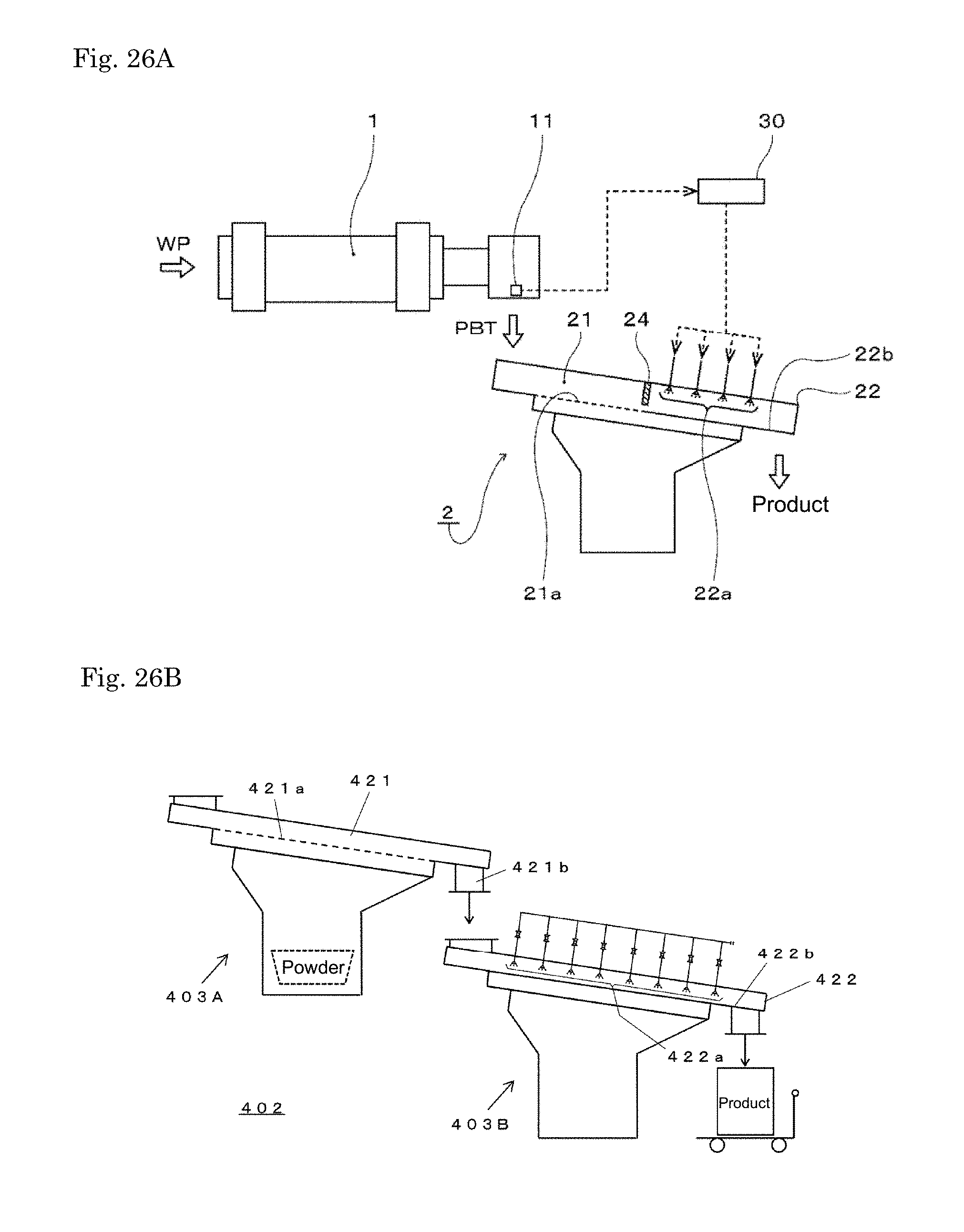
D00014

P00899

XML
uspto.report is an independent third-party trademark research tool that is not affiliated, endorsed, or sponsored by the United States Patent and Trademark Office (USPTO) or any other governmental organization. The information provided by uspto.report is based on publicly available data at the time of writing and is intended for informational purposes only.
While we strive to provide accurate and up-to-date information, we do not guarantee the accuracy, completeness, reliability, or suitability of the information displayed on this site. The use of this site is at your own risk. Any reliance you place on such information is therefore strictly at your own risk.
All official trademark data, including owner information, should be verified by visiting the official USPTO website at www.uspto.gov. This site is not intended to replace professional legal advice and should not be used as a substitute for consulting with a legal professional who is knowledgeable about trademark law.