A Vertical Packaging Machine
Fioravanti; Andrea ; et al.
U.S. patent application number 16/097254 was filed with the patent office on 2019-04-18 for a vertical packaging machine. The applicant listed for this patent is MBP S.r.l.. Invention is credited to Andrea Fioravanti, Marco Pavan.
| Application Number | 20190112089 16/097254 |
| Document ID | / |
| Family ID | 56801687 |
| Filed Date | 2019-04-18 |


| United States Patent Application | 20190112089 |
| Kind Code | A1 |
| Fioravanti; Andrea ; et al. | April 18, 2019 |
A VERTICAL PACKAGING MACHINE
Abstract
A vertical packaging machine (10) comprises a carcass having a substantially quadrangular plan, a forming tube (12) mounted on one side of said carcass and adapted to create packages of a product through the use of a continuous advancement film (13) supplied by a reel (14) mounted on a shaft (16) and arranged in a housing provided in a side of the carcass adjacent to that on N which said forming tube (12) is mounted, the unwinding of said film from said reel being performed by a motor (17) equipped with an appropriate means for controlling the unwinding of said film (13), said carcass being further equipped with a horizontal flat surface (21) on which the film (13) unwound from said reel is made to transit and change direction by 90.degree. for being then directed towards said forming tube (12). The 90.degree. direction change of said film (13) is performed through a substantially triangular frame (20) arranged on said horizontal flat surface (21) of said carcass, a first side of which frame is arranged at 45.degree. with respect to the respective advancement directions of the film as respectively unwound from the reel (14) and entering into the forming tube (12); a second side of said frame (20) is constrained to a slide (22) linearly movable through an appropriate motor means (24) along a movement lane (23) parallel to the advancement direction of said film (12) on said horizontal flat surface (21) before the 90.degree. direction change performed through said substantially triangular frame (20) takes place.
| Inventors: | Fioravanti; Andrea; (Castiglione Delle Stiviere, IT) ; Pavan; Marco; (Castiglione Delle Stiviere, IT) | ||||||||||
| Applicant: |
|
||||||||||
|---|---|---|---|---|---|---|---|---|---|---|---|
| Family ID: | 56801687 | ||||||||||
| Appl. No.: | 16/097254 | ||||||||||
| Filed: | April 18, 2017 | ||||||||||
| PCT Filed: | April 18, 2017 | ||||||||||
| PCT NO: | PCT/IB2017/052202 | ||||||||||
| 371 Date: | October 27, 2018 |
| Current U.S. Class: | 1/1 |
| Current CPC Class: | B65B 57/08 20130101; B65B 59/02 20130101; B65B 2210/04 20130101; B65B 9/20 20130101; B65B 59/003 20190501; B65B 57/04 20130101; B65B 41/18 20130101; B65B 61/025 20130101 |
| International Class: | B65B 41/18 20060101 B65B041/18; B65B 57/04 20060101 B65B057/04; B65B 57/08 20060101 B65B057/08; B65B 59/02 20060101 B65B059/02; B65B 61/02 20060101 B65B061/02; B65B 9/20 20060101 B65B009/20 |
Foreign Application Data
| Date | Code | Application Number |
|---|---|---|
| Apr 28, 2016 | IT | 102016000043541 |
Claims
1.-7. (canceled)
8. A vertical packaging machine comprising a framework with a substantially quadrangular plan, a forming tube mounted on one side of said framework for manufacturing a package of a product through the use of a continuously advancing film supplied by a reel mounted on a shaft and arranged in a housing provided in a side of the framework adjacent to that on which said forming tube is mounted, the unwinding of said film from said reel being performed by a motor equipped with an unit for controlling the unwinding of said film, said framework further comprising a horizontal flat surface on which the film passes and changes direction by 90.degree. when unwound from said reel being then directed towards said forming tube, wherein the 90.degree. direction change of said film is performed through a triangular frame arranged on said horizontal flat surface of said framework, a first side of said triangular frame being arranged at 45.degree. with relative to the respective advancement directions of the film as unwound from the reel and entering into the forming tube, whereby a second side of said frame is connected to a slide linearly movable through a motor along a movement lane parallel to the advancement direction of said film (on said horizontal flat surface before the 90.degree. direction change takes place performed through said triangular frame.
8. The machine of claim 7, wherein said first side of said triangular frame comprises a tubular element rigidly connected to the frame and carrying out a linear translation with the frame, said film being in operation arranged in contact with said tubular element which comprises a series of holes for the injection of compressed air in order to create an air cushion limiting friction between the film and the tubular element in the contact zone where the 90.degree. direction change of said film takes place.
9. The machine of claim 8, wherein the linear translation of said tubular element determines the variation of the position of the film based on type, shape and dimensions of the package to be manufactured in the forming tube, and determines the centering and the positioning of the film at a folding bell arranged at the inlet to said forming tube.
10. The machine of claim 7, further comprising a reel change unit arranged on said framework, downstream of the shaft on which said reel is mounted, in correspondence of which unit either films belonging to two different reels are joined to each other, or another reel having a different format with respect to the previous one being processed is mounted on the shaft.
11. The machine of claim 10, further comprising an accumulation unit formed by a series of adjacent rollers on the surface of which the moving film is passed, thereby forming a supply of film necessary for allowing an intermittent advancement of the film itself into the forming tube.
12. The machine of claim 7, further comprising a film labelling unit.
13. The machine of claim 7, further comprising a bracket carrying a sensor for constantly monitoring any slippage of the film, said sensor being connected to an electronic control unit which in turn controls the unwinding speed of the film from the reel.
Description
FIELD OF APPLICATION
[0001] The present invention relates to a vertical packaging machine for the production of sealed bags containing products of various kinds, mainly although not exclusively food products.
[0002] More particularly, the following invention relates to a vertical packaging machine whose characteristic is that of being equipped with a means for unwinding the film which allows lost time to be reduced during format changes due to mechanical adjustments of the reel unwinding zone.
[0003] The system also prevents film slippage phenomena due to mechanical inertia when the film is drawn for forming the bag.
[0004] The packaging machine according to the invention provides a film unwinding system mounted on the lateral part and not, as normally happens, on the rear part of the machine.
[0005] In the lower zone of this device, the speed of the film unwound during normal production is uniform, but the rotation speed of the motor that unwinds the reel varies automatically as a function of the diameter of the latter.
[0006] The present invention is advantageously applied in the sector of packaging machines for products of various kinds and mainly food products.
PRIOR ART
[0007] It is known that sealed packages normally available in the supermarkets containing products of various kinds, for example food products, are produced by automatic machines known as packaging machines.
[0008] There are various types of these machines of different types and, among these, there is also a version that is normally defined as a vertical packaging machine. The latter comprises a dosing device positioned in the uppermost part and from which the product to be packaged is left to drop for being conveyed into a vertical metal tube of a variable width and reduced length, known as a forming tube.
[0009] Outside the latter, the film is wound which advances around it through a drawing system comprising rubber coated belts and curved sheet metal parts, arranged around the forming tube.
[0010] By using the rubber coated belts it is possible to move the edges towards one another for sealing both vertically and horizontally hence creating the sealed package.
[0011] Traditional sealing systems installed on the machine, based on the chosen configuration, may sometimes seal the package only with the film on the stationary forming tube, hence making it necessary for the drawing members to intervene with an intermittent type of motion which consequently causes strong accelerations.
[0012] The set of devices mounted on the vertical packaging machine appointed to unwind the reel from which the film comes for forming the package, precisely due to such strong accelerations, limit the speed of the system and generate slippage which in turn has a negative effect on the quality of the package which could be aesthetically unpleasant or in extreme cases not correctly sealed.
[0013] Another problem connected with traditional film unwinding devices mounted on vertical packaging machines is highlighted during format changes.
[0014] As normally happens, users of these packaging machines need to produce packages of various sizes, therefore they are obliged to manually replace the device called the forming tube with other forming tubes of different sizes. To do this, they must necessarily also perform various mechanical adjustments on the film unwinding devices to adapt them to the new dimensions of the package to be produced with a notable loss of time before starting again with new production.
[0015] All this has a negative effect on the packaging processes, and causes an excessive lengthening of the time required for bag format changes, causing a condition such that, when added to the film advancement problem, prevents the production costs being contained also due to the need for frequent intervention by appointed personnel.
[0016] Document US 2015/0020483 describes a multi-line packaging machine equipped with four forming tubes mounted in parallel and four respective film unwinding reels. Each of the packaging lines envisages a triangular shaped fixed frame which allows a 90.degree. direction change of the film to be performed unwound from a reel and advanced towards a forming tube. However, a movement means of said triangular frame is not provided and therefore an adaptation and compensation means acting to keep the film centred with respect to the forming tube is not provided.
DESCRIPTION OF THE INVENTION
[0017] The present invention sets out to provide a vertical packaging machine for producing sealed bags containing products of various kinds which is equipped with a film unwinding device that facilitates bag format changes, thus creating a condition able to eliminate or at least reduce the drawbacks highlighted above.
[0018] The main advantages of this solution firstly regard the possibility to overcome the production speed limit imposed by the mechanical inertia produced by the film unwinding devices used up to now.
[0019] According to the present invention the advantages of this solution also regard the possibility to limit the format change time, avoiding a multitude of mechanical adjustments.
[0020] In particular, the system also prevents the occurrence of film slippage due to mechanical inertia when the film is drawn for forming the bag.
[0021] This is obtained through a vertical packaging machine for producing sealed bags equipped with a device for the easy unwinding of the film, whose characteristics are described in the main claim.
[0022] The dependent claims of the present solution delineate advantageous embodiments of the invention.
[0023] The main advantage of this solution regards the fact that the above machine provides a film unwinding system mounted on the lateral part of the packaging machine hence determining a mechanical condition such as to allow a reduction of losses of time during format changes caused by mechanical adjustments on the reel unwinding zone.
[0024] A further advantage offered by the invention is that relative to the possibility to prevent appointed personnel having to perform numerous and various mechanical adjustments on the film unwinding devices during format change operations. These operations were necessary for adapting the machine to the new dimensions of the package to be produced which, according to known solutions, caused a notable loss of time before starting again with new production.
ILLUSTRATION OF THE DRAWINGS
[0025] Further characteristics and advantages of the invention will be evident from reading the following description of an embodiment of the invention by way of non-limiting example with the aid of the figures illustrated in the appended tables of drawings, in which:
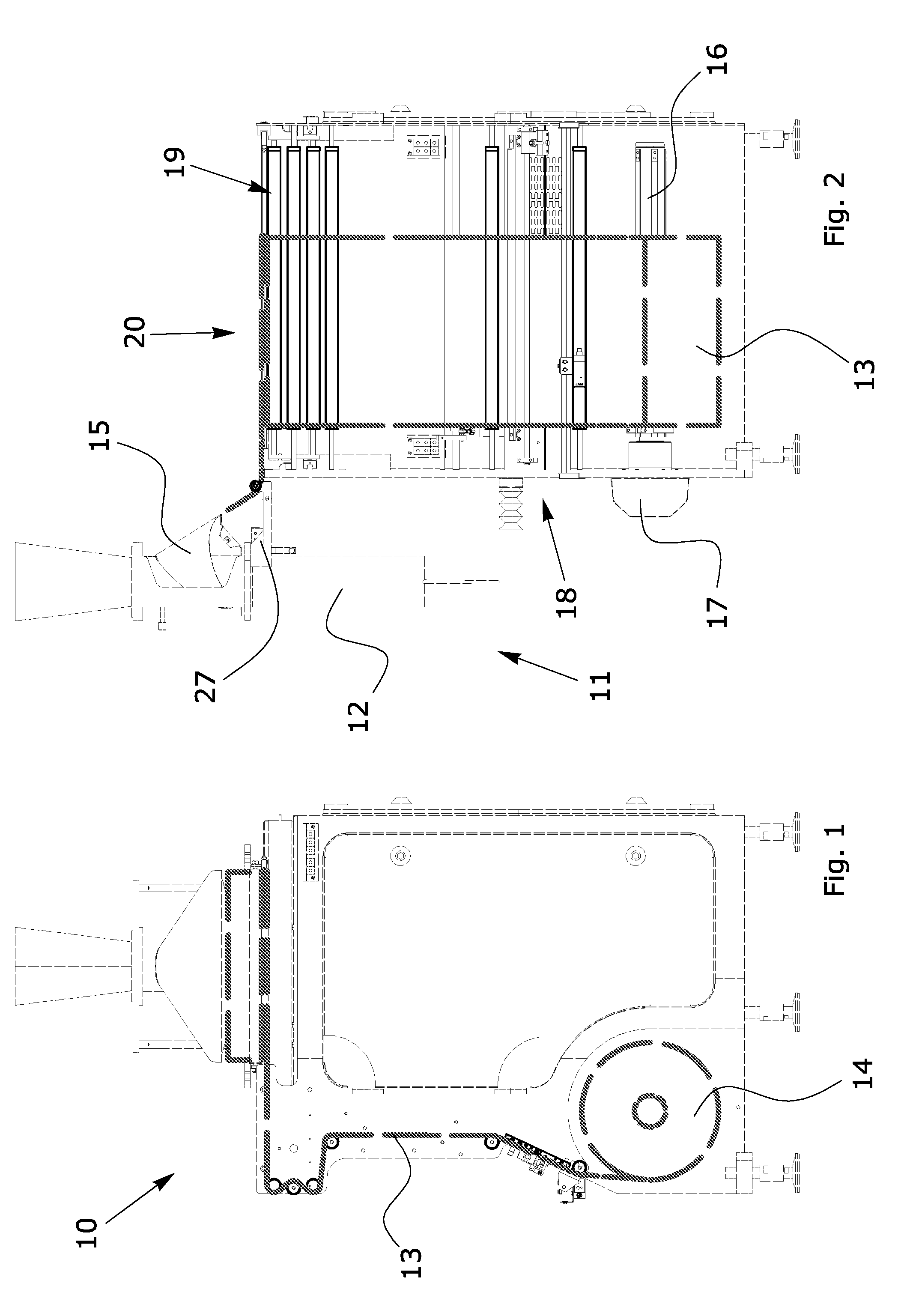
[0026] FIG. 1 represents a schematic side view highlighting a vertical packaging machine according to the invention, which highlights the path of the film;
[0027] FIG. 2 illustrates a schematic side view highlighting the same packaging machine according to a different angle;
[0028] FIG. 3 is a schematic and perspective view of the machine according to the invention provided with the means according to the invention for unwinding the film;
[0029] FIG. 4 shows a plan view of the vertical packaging machine provided with the means according to the invention for unwinding the film.
DESCRIPTION OF AN EMBODIMENT OF THE INVENTION
[0030] With reference to the appended figures, and initially in particular to FIG. 1, 10 generally indicates a vertical packaging machine equipped with the film unwinding system according to the invention.
[0031] The vertical packaging machine has a substantially prismatic conformation on four sides and with a vertical extension, and is equipped with a carcass having a front sector 11 in which the packages of the product to be packaged are formed at a forming tube 12.
[0032] The packages of product to be packaged are realised using a film 13 made of synthetic material with continuous advancement supplied by a reel 14 placed in its own housing in the lower part of the machine on one side of the carcass adjacent to the one on which the forming tube 12 is mounted. Such film 13 dispensed by the reel 14, is made to rise from the lower part to the upper part of the machine so as to reach the forming tube 12 passing from a folding bell 15 arranged at the inlet of said forming tube 12.
[0033] According to a characteristic of the invention, the film unwinding devices are mounted on one side of the vertical packaging machine and not on the rear part as happens in solutions of the prior art, thus allowing an innovative system to be used for the adjustment and adaptation to the different film formats subsequently used.
[0034] Proceeding with respect to the film unwinding order, the first device encountered is a support shaft 16 for supporting the reel 14 from which the film is unwound, which is fixed directly onto the main front plate of the carcass to which most of the machine's mechanical components are anchored.
[0035] The shaft 16 of the reel 14 is activated and controlled by a motor 17 which, through a reducer of the number of revolutions, makes the shaft and the reel rotate. The motor 17 is equipped with a device for controlling the unwinding of the reel.
[0036] According to an embodiment of the invention, it is envisaged that the film 13 rising upwards to reach the forming tube 12 passes through distinct operating units placed laterally to the packaging machine according to this order: a unit 18 for facilitating the cutting of the film; subsequently, according to the work requirements, printing and label application units, an accumulation device 19 which allows the intermittent motion necessary for the sealing systems on the forming tube.
[0037] According to a characteristic of the invention, a folding guide 20 is further provided comprising a triangular shaped frame which changes the unwinding direction by 90.degree. and inverts the side of the film so as to bring it onto the forming tube 12 in the correct way and direction.
[0038] In relation to the reel unit 14 of the film 13, during normal operation of the machine, the unwinding of the film in the first part of the unwinding device takes place at a uniform speed.
[0039] At the reel unit 14 an encoder 21 is provided associated with a small rubber-coated wheel, which allow the constant measurement of the film which is being unwound.
[0040] Considering that while the film is being unwound, the reel reduces in diameter, through a mathematical algorithm, the encoder sends signals to the computer which manages the machine, continuously correcting the speed of the motor for the rotation of the reel.
[0041] With the data acquired, the computer allows the operator to view information related to the diameter of the reel and other production-related data allowing all the rollers that rotate to accompany the film during its unwinding in the zone where the speed is uniform, to turn at the same speed, hence not opposing any force of inertia to the film.
[0042] Through these rollers, maintaining a constant speed and passing into the zone where the joining of the film is facilitated for the replacement of the reel, the film reaches the labelling zone, in which one or more pieces of equipment may provide for gluing the label and possibly printing the date or batch number or other information.
[0043] According to an embodiment of the invention, for aligning the position of the drawing already printed on the film with the printed date or the glued labels, a photocell 22 is used which detects a coloured reference notch on the film so that, by measuring the movement, using the same encoder already used for the speed, an electronic control unit can decide when to launch the printing or labelling command.
[0044] Therefore, without operating on the movement of rollers or mechanical parts, at the format change the operator can simply set the necessary package through a monitor connected to the computer of the electronic control unit and the system remembers at what height the date and the label had been positioned.
[0045] At the end of the printing and labelling step, the film 13 crosses a roller-operated accumulation device 19 which determines the intermittent motion necessary for the sealing systems on the forming tube.
[0046] The accumulation device 19 comprises 3 or more rollers, half of which are coupled to movable supports which in turn are moved by the stem of a mechanical actuator 23 where the thrust force is decided by the computer based on the accelerations in order to cancel out the inertia caused by the moving mechanical mass.
[0047] As can be seen in FIG. 3, once the accumulation device 19 has been passed, the film passes into the triangular shaped folding guide 20 which changes the unwinding direction by 90.degree. and inverts the side of the film so as to bring it onto the forming tube 12 in the correct way and direction.
[0048] More precisely, and as can be seen in FIGS. 3 and 4, the folding device 20 is arranged at the upper flat surface 21 of the carcass of the machine and comprises a substantially triangular shaped frame, one of whose sides is arranged according to a 45.degree. angle with respect to the front wall and the lateral wall of the machine. According to an important characteristic of the invention, another side of said triangular frame, in particular the one facing the front of the machine, is coupled to a movable slide 22 in linear translation along a rectilinear guide comprising a recirculating ball screw 23 activated in the rotary sense by an electric motor 24 arranged axially on an end of the screw itself, said rectilinear guide being substantially parallel to the advancement direction of the film on said flat surface as it is unwound from the reel.
[0049] On the side of the frame of said guide 20 which is arranged according to a 45.degree. angle with respect to the front wall of the machine, a respective tubular element 25 is mounted, which is solidly constrained to the frame and that can therefore translate in the linear sense together therewith through the activation of the motor 24 which moves the slide 22 on which it is applied.
[0050] On the tubular element 25, which is arranged according to a 45.degree. angle with respect to the front wall of the machine, holes are advantageously made for the injection of compressed air in order to create a cushion that limits friction between the film and the metal of the folding device.
[0051] As can be easily understood from the examination of the appended figures, the lateral movements of the tubular element 25 which is movable together with the guide 20 determine the variation of the position of the film based on the type, shape and dimensions of the package to be created, allowing the format change through the activation of the motor 24 which automatically moves the guide bringing it to the optimal position with that determined format.
[0052] During the normal operation of the machine, the movement of the tubular element 25 determines the centring and position of the film, which is arranged first on the folding bell 15 and then on the forming tube 12, at which it is folded in the tubular sense and sealed and cut to measure after the filling of the product to be packaged.
[0053] The linear translation movement of the triangular frame and the tubular element 25 therefore allows the automatic variation of the format of the film and its centring with respect to the forming tube 12, avoiding the manual controls that were necessary with systems of the prior art and reaching the objects of the present invention.
[0054] The movement of the tubular element 25, being very close to the folding bell, also allows the centring of the film much more quickly and dynamically with respect to systems of the prior art.
[0055] This solution as a whole also allows the operator to view the part of film that is normally screen printed on the whole length of the film unwinding device, visually checking if the printing position of any expiry date and any label are correct, solving the data control problems of traditional systems.
[0056] With the screen printing facing towards the operator and not towards the machine frame, the adhesive tape that is normally used for joining the new reel of film is also glued in the external side of the bag, thus facilitating the identification and discarding of these packages.
[0057] Another advantage of this solution is comprised of the fact that the end stroke ring where the reel 14 rests on the unwinding shaft 16 never needs to be adjusted, also limiting in this case the mechanical adjustments to be performed by personnel.
[0058] At the forming tube 12, a bracket is fixed, onto which a sensor 27 is coupled which constantly monitors any slippage of the film. In the event of a format change, the sensor may be uncoupled from the old forming tube to be put onto the new one with an already correct position, hence preventing any mechanical adjustments.
[0059] In the event of slippage on the film side, the sensor 27 measures the new position and consequently reports to the computer which manages the system the need to move the tubular element 25 through the electrical motor 24 for compensating the slippage of the film.
[0060] The invention has been described in the above with reference to a preferred embodiment thereof. However it is clear that the invention is susceptible to numerous variants which fall within the scope thereof, and which are technically equivalent.
* * * * *
D00000
D00001
D00002
XML
uspto.report is an independent third-party trademark research tool that is not affiliated, endorsed, or sponsored by the United States Patent and Trademark Office (USPTO) or any other governmental organization. The information provided by uspto.report is based on publicly available data at the time of writing and is intended for informational purposes only.
While we strive to provide accurate and up-to-date information, we do not guarantee the accuracy, completeness, reliability, or suitability of the information displayed on this site. The use of this site is at your own risk. Any reliance you place on such information is therefore strictly at your own risk.
All official trademark data, including owner information, should be verified by visiting the official USPTO website at www.uspto.gov. This site is not intended to replace professional legal advice and should not be used as a substitute for consulting with a legal professional who is knowledgeable about trademark law.