Bubble Producing Device, Toy, Or Wand With Bubble Release, Lights, And Sound
Kelly; Christopher D. ; et al.
U.S. patent application number 15/398154 was filed with the patent office on 2019-04-18 for bubble producing device, toy, or wand with bubble release, lights, and sound. The applicant listed for this patent is LightUpToys.com LLC. Invention is credited to Macaulay Bruton, Christopher D. Kelly, Joshua C. Kelly, Max Armendariz Lalama.
| Application Number | 20190111358 15/398154 |
| Document ID | / |
| Family ID | 66097244 |
| Filed Date | 2019-04-18 |


View All Diagrams
| United States Patent Application | 20190111358 |
| Kind Code | A1 |
| Kelly; Christopher D. ; et al. | April 18, 2019 |
BUBBLE PRODUCING DEVICE, TOY, OR WAND WITH BUBBLE RELEASE, LIGHTS, AND SOUND
Abstract
A device that produces bubbles and adds lighting to the bubbles being released and including a synchronized series of lights producing a light show and/or sounds, an at least three-way switch, as well as, a mechanical or electrical system with an improved engine design, chimney and extensions, as well as, an improved battery compartment.
| Inventors: | Kelly; Christopher D.; (New Albany, IN) ; Kelly; Joshua C.; (Sellersburg, IN) ; Lalama; Max Armendariz; (Sellersburg, IN) ; Bruton; Macaulay; (Louisville, KY) | ||||||||||
| Applicant: |
|
||||||||||
|---|---|---|---|---|---|---|---|---|---|---|---|
| Family ID: | 66097244 | ||||||||||
| Appl. No.: | 15/398154 | ||||||||||
| Filed: | January 4, 2017 |
| Current U.S. Class: | 1/1 |
| Current CPC Class: | A63H 5/00 20130101; A63H 33/28 20130101 |
| International Class: | A63H 33/28 20060101 A63H033/28 |
Claims
1. A device for producing bubbles comprising: At least one housing; at least one light or LED light; at least one of: at least one power source; at least one electrical connection system; at least one battery compartment; at least one battery compartment door; at least one of the following; at least one activation and/or mode switch that operates at least one mechanism and makes at least one electrical closure; at least one fan driven by an electric or mechanical motor or engine which produces an air stream from the said bubble device to an ambient environment; a dispensing device, such as, a dispensing ring with a dispensing aperture, venturi, chimney, or other dispensing device provided or provided therein; at least one electric or mechanical pump that receives bubble solution from at least one delivery tube and outputs bubble solution to at least one feed line that feeds said bubble solution to said dispensing device, venturi, chimney, or said dispensing ring; a propelling bubble solution film applicator device, such as, a film applicator radially oriented and moving in a circular motion via the action of a motorized or mechanical central shaft, that engages bubble solution onto and/or throughout the said dispensing ring or other said dispensing device; an electromechanical power sequence activated by the initiation of the trigger mechanism, and said at least one electrical closure, which delivers electrical power from said at least one power source to said electric motor that operates said fan, said pump, said bubble solution film applicator, said at least one light, and/or a sound and/or music and/or amplification system; at least one orifice, that houses said dispensing device, venturi, chimney, or said dispensing ring and/or bubble solution film applicator, located at the surface or other location or locations of said bubble producing device, to emit bubbles through the surface of said bubble producing device, or such other location or locations as desired for any embodiment.
2. The bubble producing device of claim 1 further comprising at least one of a at least three-way activation and/or mode switch to operate at least one of: said at least one light or LED light, sound, and/or said motor, or any combination thereof, in any order or sequence thereof.
3. The bubble producing device of claim 1 further comprising of a sound amplification system and/or a sound producing device or system.
4. The bubble producing device of claim 1 further comprising of at least one light that emits upwardly and/or outwardly and/or through and/or near the at least one orifice of said bubble producing device, and thus illuminating bubbles as they pass through this at least one orifice and exit said bubble producing device.
4. a. The bubble producing device of claim 1 further comprising of at least one independent and independently programed light and/or lighting system creating a light show, light show device, and/or light show toy.
4. b. The bubble producing device of claim 4a further comprising of at least one independent and independently programed light and/or lighting system creating a light show, light show device, and/or light show toy, additionally comprising sound, and/or at least one sound device, and/or at least one sound system which is either independent, or synchronized, programed together with, sequenced with, or combined with said light show, light show device, and/or light show toy.
4. c. The bubble producing device of claim 4b further comprising that the bubbles produced are either independent, or synchronized, programed together with, sequenced with, or combined with said lights and or said sound.
5. The bubble producing device of claim 1 further comprising a sealed container with external contacts that can hold at least one removably-insertable battery, wherein the at least one removably insert able battery is contained within a sealed container with or without external contacts and said container is at least one of: isolated, water resistant, or water proof.
5. a. The invention of claim 1 further comprising that the battery pack is more isolated from the rest of the product or toy which better protects the batteries from dirt and liquids from external sources Better protects batteries from possible contamination from internal bubble solution Limits access to the inside of the product or toy via the battery door.
5. b. The invention of claim 5 wherein the battery compartment contains spacers or separators between batteries which aides in the prevention of reverse polarization.
6. The bubble producing device in claim 5 wherein said sealed container has a door on the side that is attached and separated or opened by use of an attaching and removing device and/or fastener and/or screw to be tightened to close and loosened or removed to open.
7. The bubble producing device of claim 5 wherein said sealed container allows insertion and removal of batteries from the side of said bubble producing device.
8. The bubble producing device of claim 2 wherein said at least one light is multicolored and the light therefrom generated is transmitted throughout the entirety or a portion thereof of said bubble producing device and said at least one light emitted vertically beyond the device, past, and/or through the uppermost vertical or other outermost portion of said bubble producing device, thus illuminating the bubbles as they exit said dispensing device and/or dispensing ring.
9. The bubble producing device of claim 3 wherein said at least one light partially and/or completely change colors in rhythmic time with the sound and/or music produced by said sound amplification system and/or a sound producing device or system to achieve a synchronized light and sound show.
10. The bubble producing device of claim 1 wherein said sound and/or music amplification system and/or a sound producing device or system has its own activation mechanism which allows said sound and/or music amplification system and/or sound producing device or system to be engaged or disengaged under operator control when said bubble producing device is active and emitting light and bubbles.
11. A bubble producing device of claim 1 wherein said bubble solution is at least one of: contained inside, attached, inserted, incorporated therein, decompartmentalized, and/or removably-attachable or attached, refillable bubble solution reservoir which removably-attaches to said housing.
12. A bubble producing device of claim 1 further comprising electronics that controls the lighting of said at least one light in at least one sequence.
13. The bubble producing device of claim 1 wherein said at least one activation and/or mode switch initiates at least one lighting sequence.
14. The bubble device of device claim 13 wherein said at least one lighting sequence is repetitive.
15. The bubble producing device of claim 13 wherein said at least one lighting sequence is random.
16. The bubble producing device of claim 13 wherein said at least one lighting sequence is determined by time and/or is a function of time.
17. The bubble producing device of claim 13 wherein said at least one lighting sequence incorporates constant timing.
18. The bubble producing device of claim 13 wherein said at least one lighting sequence incorporates variable timing.
19. The bubble producing device of claim 18 whereby said timing is determined by the time interval between bubbles and/or the speed and/or rate of bubble production.
20. The bubble producing device of claim 13 wherein said at least one lighting sequence incorporates a dimming function as part of said at least one lighting sequence.
21. The bubble producing device of claim 12 further comprising at least one acoustic sensor that senses acoustic energy and/or audio from the environment and converts said acoustic energy and/or audio into at least one signal used to initiate and/or affect said at least one lighting sequence.
22. The bubble producing device of claim 21 wherein said at least one signal is resolved into frequency and/or amplitude and/or a combination thereof.
23. The bubble producing device of claim 22 wherein said frequency and/or amplitude and/or a combination thereof controls and/or affects the said at least one lighting sequence and/or at least one pattern and or intensity of said at least one lighting sequence.
24. The bubble producing device of claim 1 further comprising at least one connector and/or jack for connecting to an audio source and/or power source.
25. The bubble producing device of claim 1 further comprising at least one communication device that transmits and/or receives data and/or signals in a master-slave fashion via RF and/or IR and/or other at least one other method.
26. The invention of claim 1 having at least one of at least three types of improved engines as follows: Engine type 1 as described in claim 1; And/or Engine type 2 Using a second engine embodiment which has a decreased profile width wherein the at least one bubble chimney is rotated to fit more housing outer shapes and said Chimney on said second type Engine was designed in rotated position to slim the profile, and also uses transparent plastic and housing was changed to clear plastic in order to reduce the shadows that the first engine type white plastic engine produces when the LEDs are turned on and is additionally comprising at least one added bevel gear in its gear train, Because the bubble chimney was rotated, the wiper driveshaft had to be rotated with it, So a bevel gear was added to the end so it could still connect with the gear train The 5.sup.th gear was added to change the orientation of the wiper shaft, this engine type 2 provides two main benefits wherein Changing the direction of the Chimney makes the engine more compact and therefore Engine type 2 can fit into tighter spaces in a final product design, and so there is more freedom in the shapes and sizes that can be designed, and additionally the slimmer profile further reduces the shadows that it casts in the LED or other lighting resulting in an improved light show from LED or other lighting; And/or Engine type 3 using a third engine type embodiment more flexible then engine 1 or 2 for fitting into other housing shapes also having an Improved bubble solution pump and an Improved wiper axel placement resulting from the rotated chimney and while the the hose in engine type 2 can be pushed out, the hose in Engine type 3 cannot.
27. The invention of claim 26 wherein the said engine type 3 if present is used with at least one attached or removably attached Chimney Extender;
28. The invention of claim 27 wherein the chimney extender is at least one piece of plastic that protrudes outward allowing for attaching and removing of additional parts, including but not limited to heads, body parts, robot parts, to the outer housing of a product or toy.
29. the invention of claim 28 wherein at least one hose fits over this side of said connector, the said Plastic tube connector prevents the rubber hose from being pushed out of the peristaltic pump and a Second hose fits over the side of the connector.
30. The invention of claim 26 wherein the said Improved bubble solution pump has a pump cap
31. The invention of claim 26 wherein the Axel is completely contained in the engine housing.
32. The invention of claim 1 wherein the device additionally comprises at least one sensor device or mechanism so that when the said at least one sensor device is operating and/or on, and/or activated then the at least one activation switch is triggered and/or operated and/or controlled by said sensor device thus making the bubble producing device automatic in that the activation, deactivation, and/or operation of the device is not manually operated.
33. The invention of claim 32 wherein said at least one sensor device is at least one motion sensor device.
34. The invention of claim 1 wherein the device additionally includes the following: The device is an improved battery powered device device that produces bubbles from a liquid solution and lights and sounds; And/or the bubble emitting orifice is located at the upper most position of a hand-held wand which also incorporates lighting features that emit light upwards and outwards through the orifice in which bubbles exit, thus illuminating the bubbles as they leave the toy; and/or incorporating a battery powered electromechanical mechanism which produces a steady stream of bubbles as well as music and additional lighting for a synchronized light show which is all controlled by at least one, at least three-way switch, and at least one embodiment has at least one sensor for automatic and/or continuous performance and activation; and/or device is removably attached to a cart which has at least one of a power source, at least one sensor for activation and/or automatic and/or continuous light show, sound, and/or bubble production; and/or the device is or is part of at least one of a toy, wand, cane, robot, toy sword, bubble toy, doll, action figure, toy gun, character, vehicle, aircraft, boat, spaceship, rocket, train, planet, game, or other product or consumer product.
35. The invention of claim 1 wherein said orifices are at least two or more orifices.
36. The invention of claim 1 wherein said light show is at least one of: a 360 degree light show; up to a 360 degree light show covering all directions; a light show displayed over the surface of a globe or globe like surface; said surface is one of opaque, white, transparent, colored, multi-colored, black, clear, metallic, imprinted, printed, three-dimensional, decorated,
Description
FIELD OF INVENTION
[0001] This invention is in the field of bubble producing devices, and more specifically to a battery powered device that produces lights, sounds, and bubbles from a liquid solution.
BACKGROUND OF INVENTION
[0002] There have been many bubble toys over the years that operate in various ways, However, most bubble toys are hand-held rings that are either blown through or hand-waived by the user to produce a small amount of bubbles. It is desired to provide a device that produces a steady stream of bubbles as a safe form of entertainment for a child.
[0003] The present invention in its current preferred embodiment is an improved battery powered toy device that produces bubbles from a liquid solution and lights and sounds. In the present invention, in at least one embodiment the bubble emitting orifice is located at the upper most position of a hand-held wand which also incorporates lighting features that emit light upwards and outwards through the orifice in which. bubbles exit, thus illuminating the bubbles as they leave the toy. In addition, the present invention improves the quality of play by incorporating a battery powered electromechanical mechanism which produces a steady stream of bubbles as well as music and
[0004] Additional lighting for a synchronized light show which is all controlled by at least one, at least three-way switch, and at least one embodiment has at least one sensor for automatic. and/or continuous performance and. activation. In at least one embodiment the device is removably attached to a cart which has at least one of a power source, at least one sensor for activation and/or automatic and/or continuous light show, sound, and/or bubble production. In at least one embodiment the device is or is part of at least one of a toy, wand, cane, robot, character, vehicle, game, or other product or consumer product.
[0005] The invention in at least one embodiment light show is at least one of: a 360 degree light show; up to a 360 degree light show covering all directions; a light show displayed over the surface of a globe or globe like surface; the surface is one of opaque, white, transparent, colored, multi-colored, black, clear, metallic, imprinted, printed, three-dimensional and/or, decorated. Furthermore, the present invention can be manufactured in a quick and cost-effective manner.
SUMMARY OF INVENTION
[0006] A device for producing bubbles comprising: At least one housing; [0007] at least one light or LED light; at least one of: at least one power source; at least one electrical connection system; at least one battery compartment; at least one battery compartment door; at least one of the following; at least one activation and/or mode switch that operates at least one mechanism and makes at least one electrical closure; at least one fan driven by an electric or mechanical motor or engine which produces an air stream from the said bubble device to an ambient environment; a dispensing device, such as, a dispensing ring with a dispensing aperture, venturi, chimney, or other dispensing device provided or provided therein; at least one electric or mechanical pump that receives bubble solution from at least one delivery tube and outputs bubble solution to at least one feed line that feeds said bubble solution to said dispensing device, venture, chimney, or said dispensing ring; a propelling bubble solution film applicator device, such as, a film applicator radially oriented and moving in a circular motion via the action of a motorized or mechanical central shaft, that engages bubble solution onto and/or throughout the said dispensing ring or other said dispensing device; and electromechanical power sequence activated by the initiation of the trigger mechanism, and said at least one electrical closure, which delivers electrical power from said at least one power source to said electric motor that operates said fan, said pump, said bubble solution film applicator, said at least one light, and/or a sound and/or music and/or amplification system; an orifice, that houses said bubble solution film applicator, located at the most vertical and upward facing surface of said bubble producing device, to emit bubbles through the most vertical and upward facing surface of said bubble producing device, or such other location as desired for any embodiment. Further may be comprised of at least one of a at least three-way activation and/or mode switch to operate at least one of said at least one light or LED light, sound, and/or said motor, or any combination thereof, in any order or sequence thereof. May further be comprised of a sound amplification system and/or a sound producing device or system. The bubble producing device may further be comprising of at least of e light that emits upwardly and/or outwardly and/or through and/or near the at least one orifice of said bubble producing device, and thus illuminating bubbles as they pass through this at least one orifice and exit said bubble producing device. The bubble producing device may further be comprising of at least one independent and independently programed light and/or lighting system creating a light show, light show device, and/or light show toy. The bubble producing device may further be comprised of at least one independent and independently programed light and/or lighting system creating a light show, light show device, and/or light show toy, additionally comprising sound, and/or at least one sound device, and/or at least one sound system which is either independent, or synchronized, programed together with, sequenced with, or combined with said light show, light show device, and/or light show toy. The bubble producing device may be further comprised so that the bubbles produced are either independent, or synchronized, programed together with, sequenced or combined with lights and or sound. The bubble producing device may further be comprising a sealed container with external contacts that can hold at least one removably-insertable battery, wherein the at least one removably-insertable battery is contained within a sealed container with external contacts. The invention may further be comprised with that the battery pack is more isolated from the rest of the product or toy which better protects the batteries from dirt and liquids from external sources Better protects batteries from possible contamination from internal bubble solution Limits access to the inside of the product or toy via the battery door. The bubble producing device may have that the sealed container has a door on the side that is attached and separated or opened by use of an attaching and removing device and/or fastener and/or screw to be tightened to close and loosened or removed to open. The bubble producing device may have wherein said sealed container allows insertion and removal of batteries from the side of the bubble producing device. The bubble producing device may be wherein said at least one light is multicolored and the light therefrom generated is transmitted throughout the entirety or a portion thereof of the bubble producing device and said at least one light emitted vertically beyond the device, past, and/or through the uppermost vertical or other outermost portion of said bubble producing device, thus illuminating the bubbles as they exit said dispensing device and/or dispensing ring. The bubble producing device can have wherein said at least one light partially and/or completely change colors in rhythmic time with the sound and/or music produced by said sound amplification system and/or a sound producing device or system to achieve a synchronized light and sound show. The bubble producing device can include wherein said sound and/or music amplification system and/or a sound producing device or system has its own activation mechanism which allows said sound and/or music amplification system and/or sound producing device or system to be engaged or disengaged under operator control when the bubble producing device is active and emitting light and bubbles. The bubble producing device can include bubble solution contained inside a removably-attachable, refillable bubble solution reservoir which removably-attaches to said housing. The bubble producing device can timber comprise electronics that controls the lighting of at least one light in at least one sequence. The bubble producing device can have at least one activation and/or mode switch initiating at least one lighting sequence. The bubble device can have at least one lighting sequence is repetitive. The bubble producing device can have at least one lighting sequence that is random. The bubble producing device can have wherein the at least one lighting sequence is determined by time and/or is a function of time. The bubble producing device can have wherein said at least one lighting sequence incorporates constant timing and./or wherein said at least one lighting sequence incorporates variable timing and/or whereby said timing is determined by the time interval between bubbles and/or the speed and/or rate of bubble production and/or wherein said at least one lighting sequence incorporates a dimming function as part of said at least one lighting sequence and/or wherein it further comprising at least one acoustic sensor that senses acoustic energy and/or audio from the environment and converts said acoustic energy and/or audio into at least one signal used to initiate and/or affect said at least one lighting sequence and/or wherein said at least one signal is resolved into frequency and/or amplitude and/or a combination thereof and/or wherein said frequency and/or amplitude and/or a combination thereof controls and/or affects the said at least one lighting source and/or at least one pattern and or intensity of said at least one lighting sequence and/or it further comprising at least one connector and/or jack for connecting to an audio source and/or power source and/or the device further comprising at least one communication device that transmits and/or receives data and/or signals in a master* slave fashion via RE and/or IR and/or other at least one other method and/or The invention may have at least one of at least three types of improved engines as follows: [0008] Engine type 1 as described in claim 1; [0009] And/or [0010] Engine type 2 Using a second engine embodiment which has a decreased profile width wherein the at least one bubble chimney is rotated to fit more housing outer shapes and said Chimney on said second type Engine was designed in rotated position to slim the profile, and also uses transparent plastic and housing was changed to clear plastic in order to reduce the shadows that the first engine type white plastic engine produces when the LEDs are turned on and is additionally comprising at least one added bevel gear in its gear train, Because the bubble chimney was rotated, the wiper driveshaft had to be rotated with it, A bevel gear was added to the end so it could still connect with the gear train The 5th gear was added to change the orientation of the wiper shaft, this engine type 2 provides two main benefits wherein Changing the direction of the Chimney makes the engine more compact and therefore Engine type 2 can fit into tighter spaces in a final product design, and so there is more freedom in the shapes and sizes that can be designed, and additionally the slimmer profile further reduces the shadows that it casts in the LED or other lighting resulting in an improved light show from LED or other lighting; [0011] And/or [0012] Engine type 3 using a third engine type embodiment more flexible then engine 1 or 2 for fitting into other housing shapes also having an Improved bubble solution pump and an Improved wiper axel placement resulting from the rotated chimney and while the hose in engine type 2 can he pushed out, the hose in Engine type 3 cannot. [0013] The invention may have that wherein the engine type 3 if present is used with at least one attached or removably attached Chimney Extender; [0014] The invention of claim may have wherein the chimney extender is at least one piece of plastic that protrudes outward allowing for attaching and removing of additional parts, including but not limited to heads, body parts, robot parts, to the outer housing of a product or toy. The invention may be wherein at least one hose fits over this side of said connector; the said plastic tube connector prevents the rubber hose from being pushed out of the peristaltic pump and a second hose fits over the side of the connector. The invention may include that the said Improved bubble solution pump has a pump cap. The invention may include wherein the Axel is completely contained in the engine housing. The invention may include that wherein the device additionally comprises at least one sensor device or mechanism so that when the said at least one sensor device is operating and/or on, and/or activated then the at least one activation switch is triggered and/or operated and/or controlled by said sensor device thus making the bubble producing device automatic in that the activation, deactivation, and/or operation of the device is not manually operated. The invention may include wherein said at least one sensor device is at least one motion sensor device. [0015] The present invention may be a bubble producing device for producing bubbles from bubble solution. In one preferred embodiment, the present invention may be shaped like a wand and can include: a housing, at least one light, at least one power source that can be at least one battery contained within a battery compartment, an electrical connection system, a triggering or activating and/or mode switch that can operate at least one mechanism and makes at least one electrical closure, a fan driven by an electric motor which produces an air stream from the bubble toy device to an ambient environment, a dispensing ring with a dispensing aperture provided therein, an electric pump that receives bubble solution from a delivery tube and outputs bubble solution to a feed line that feeds bubble solution to the dispensing ring; a propelling bubble solution film applicator, radially oriented and moving in a circular motion via the action of a motorized central shaft that engages bubble solution onto and/or throughout the dispensing ring; and electromechanical power sequence activated by the initiation of the trigger mechanism, and at least one electrical closure, which delivers electrical power from at least one power source to the electric motor that operates the fan, the pump, the film-applying mechanism, at least one light, and/or a sound and/or music amplification system. In this embodiment, an exit orifice from which bubbles emit houses the bubble dispensing ring, which may be located at the topmost vertical and upward facing surface of the toy device, to emit bubbles through the most vertical and upward facing surface of the toy. It is a primary objective of the present invention that the bubble producing device may incorporate a series of lights and a sound amplification system which may be individually, or jointly, activated by triggering a switch and/or a mode switch. This can be a multi-position switch. This series of lights and lighting configuration may be integrated into the design to achieve the illumination of varying colors of light throughout the entirety or a portion thereof of the invention. In addition, the invention may include lighting which is directed upwardly and outwardly through and/or near the source of the bubble exiting orifice, to achieve illumination of the bubbles as they leave the toy. [0016] It is another objective of the present invention to provide an easily accessible battery compartment. In one preferred embodiment, the present invention may include a sealed container with external contacts that can hold at least one removably-insertable battery, wherein the at least one removably-insertable battery may be contained within a sealed container with external contacts. In addition, the present invention may integrate a sealed container that provides a door on the side of the invention that may be attached and separated or opened by use of an attaching and removing device, or fastener, or screw to be tightened to close and loosened or removed to open. It is yet another objective of the present invention to provide lights which may be multicolored and transmitted through the entirety or a portion thereof of the device and/or at least one light emitted vertically beyond the device, past, and/or through, the upper most vertical portion of the toy device, thus illuminating the bubbles as they exit the dispensing ring. In this embodiment, the present invention may utilize a series of lights, partially, or as a complete series, which can change colors in rhythmic time with the sound and/or music produced by the toy device to achieve a synchronized show between the lights and sounds. The invention may integrate lighting that is triggered by acoustical amplitude and/or frequency, or movement sensors which may trigger and/or modify at least one pattern of lighting. In addition, the lighting may also be non-rhythmic, timed, consistent or inconsistent and intermittently variable in timing and variable brightness and/or dimness. This can involve a controlled dimming function.
[0017] It is yet another objective of the present invention to include an alternative playing method for one embodiment of the invention, in which the user can set a mode switch to enable or disable the sound and/or music. In this preferred embodiment, the present invention may include a sound amplification system and/or a sound producing device or system, which has its own activation mechanism, which may allow the sound amplification system and/or sound producing device or system to be engaged or disengaged under user control when the bubble producing device is active and emitting light and bubble. It is yet another objective of the present invention that the present invention may include a refillable reservoir for bubble solution. [0018] Although preferred embodiments of the present invention have been described herein it will be understood by those skilled in the art that the present invention should not be limited to the described preferred embodiments. Rather, various changes and modifications can be made within the spirit and scope of the present invention.
[0019] All the material in this patent document is subject to copyright protection under the copyright laws of the United States and other countries. The copyright owner has no objection to the facsimile reproduction by anyone of the patent document or the patent disclosure, as it appears in official governmental records but, otherwise, all other copyright rights whatsoever are reserved.
SOME KEY COMPONENTS
[0020] 1 the device 2 handle/housing (two pieces) 3 removeably-attachable reservoir 4 globe (two pieces) 5 battery compartment door 6 switch (three position up: lights, sounds, bubbles 1 mid: off 1 down: light and sound, no bubbles) 7 top outer ring on globe 9 globe securing screw holes 10 exit orifice from which bubbles emit 11 inner bubble dispensing ring 12 rotating film applicator 13 audio grill 14 return line drain 15 seal cap (with threading) 17 reservoir to pump input 18 pump output feed line to dispensing ring sub-assembly 20 external LED (at least one) 21 motor (not shown and internally located) 22 fan (not shown and internally located) 23 fan impeller 24 fan air input 25 fan duct 26 rotating film applicator drive shaft 27 motor/pump/fan housing 28 speakers 29 negative battery terminal 30 circular ring PCB 31 globe illuminating LEDs 32 battery compartment 33 gear reduction sub system (not shown and internally located) 34 (positive displacement) pump (not shown and internally located) 35 screw receiving boss 36 motor/pump/fan housing securing screw
BRIEF DESCRIPTION OF THE DRAWINGS
[0021] FIG. 1 is a front view of an embodiment of a bubble producing toy consistent with description herein.
[0022] FIG. 2 is a top perspective view of the bubble producing toy of FIG. 1.
[0023] FIG. 3 is a partial rear view of the bubble producing toy of FIG. 1.
[0024] FIG. 4 is a partial front view of the bubble producing toy of FIG. 1.
[0025] FIG. 5 is bottom perspective view of the bubble producing toy of FIG. 1.
[0026] FIG. 6 is partial cross-sectional view illustrating an interior cavity of the bubble producing toy of FIG. 1.
[0027] FIG. 7 is second partial cross-sectional view illustrating the interior cavity of the bubble producing toy of FIG. 1.
[0028] FIG. 8 is third partial cross-sectional view illustrating the interior cavity of the bubble producing toy of FIG. 1.
[0029] FIG. 9A-C illustrate a battery pack of a bubble producing toy consistent with the description herein. FIG. 9A illustrates the battery pack without batteries inserted. FIG. 9B illustrates the battery pack with batteries inserted. FIG. 9C illustrates an enlarged view of the battery pack with batteries inserted.
[0030] FIG. 10 illustrates another embodiment of a battery pack of a bubble producing toy.
[0031] FIG. 11 illustrates an embodiment of engine 1 and engine 2 consistent with the description herein.
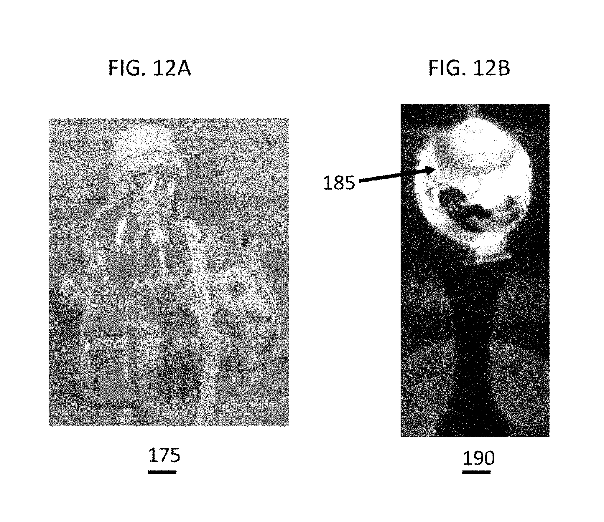
[0032] FIG. 12A-B illustrate an embodiment of engine 2. FIG. 12A illustrates an embodiment of engine 2; FIG. 12B illustrates a bubble producing wand with LEDs.
[0033] FIG. 13A-B illustrate an embodiment of a bubble chimney of engine 1 and engine 2. FIG. 13A illustrates the bubble chimney of engine 1; FIG. 13B illustrates the bubble chimney of engine 2.
[0034] FIG. 14 illustrates an embodiment of a bubble chimney.
[0035] FIG. 15A-B illustrate an embodiment of gears in engine 1 and engine 2. FIG. 15A illustrates the gears of engine 1; FIG. 15B illustrates the gears of engine 2.
[0036] FIG. 16A-B are schematics of an embodiment of a gear layout for engine 1 and engine 2. FIG. 16A is a schematic of the gear layout for engine 1; FIG. 2B is a schematic of the gear layout for engine 2.
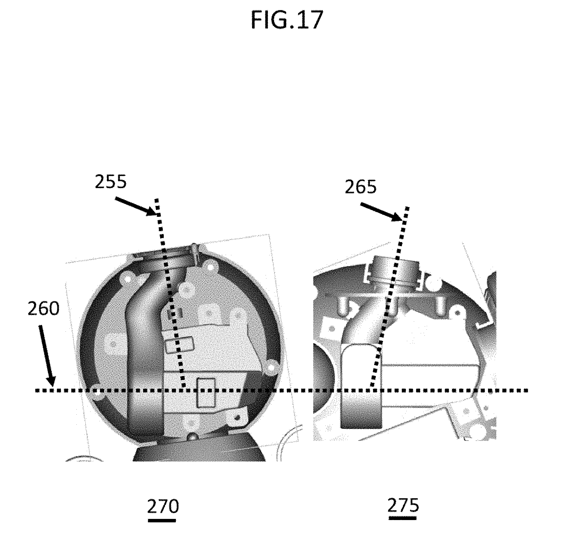
[0037] FIG. 17 illustrates an embodiment of engine 2 and of engine 3.
[0038] FIG. 18A-B illustrate embodiments of engine 2 and engine 3 in a toy. FIG. 18A illustrates engine 2 in a toy; FIG. 18B illustrates engine 3 in a toy.
[0039] FIG. 19A-B illustrate an embodiment of a bubble solution pump of engine 3. FIG. 19A illustrates the bubble solution pump of engine 3; FIG. 19B illustrates an enlarged portion of the bubble solution pump of FIG. 19A.
[0040] FIG. 20A-B illustrates an embodiment of a hose path in a bubble solution pump of engine 2 and engine 3. FIG. 20A illustrates a hose path in engine 2; FIG. 20B illustrates a hose path in engine 3.
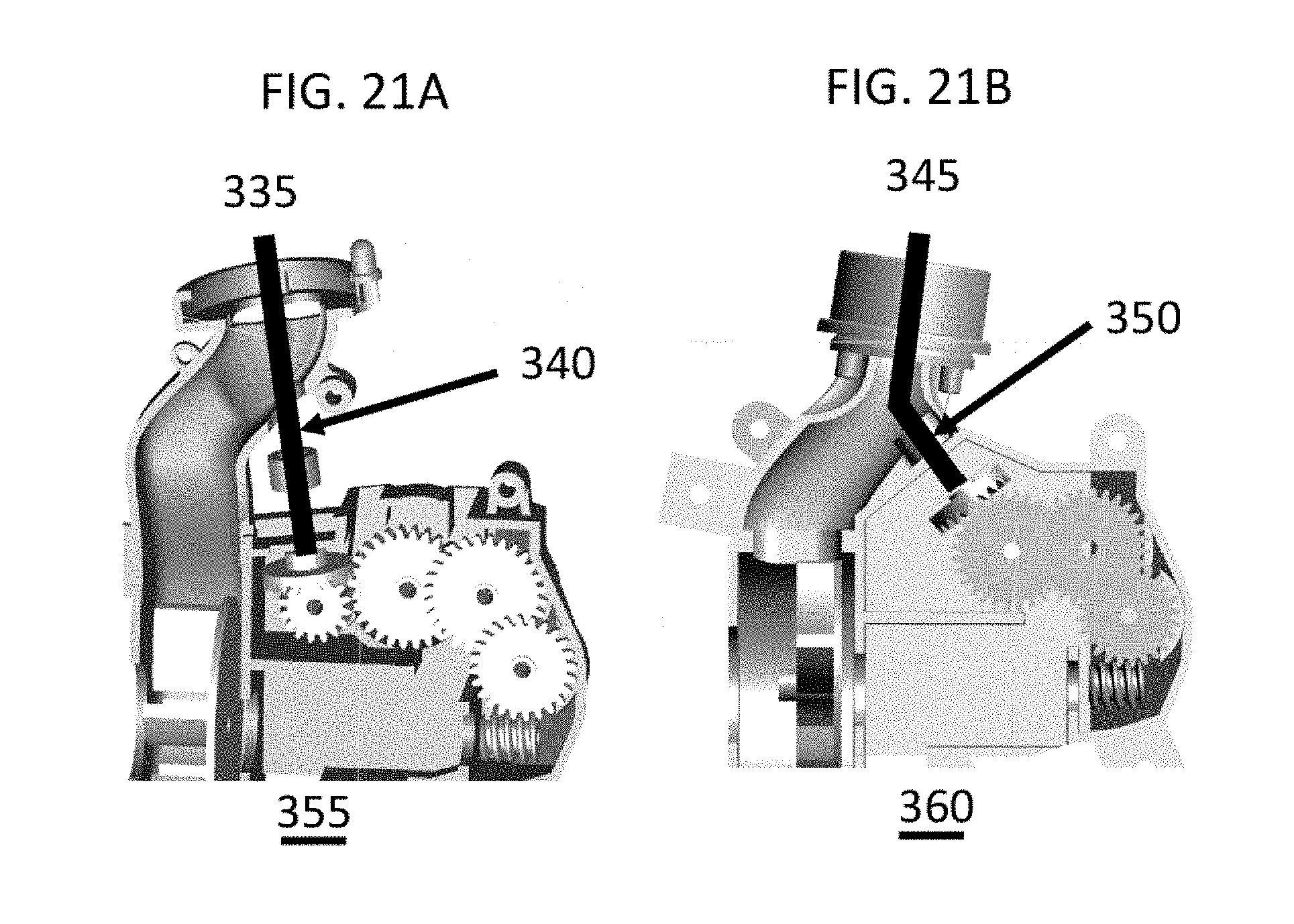
[0041] FIG. 21A-B illustrates the placement of an axel wiper in engine 2 and engine 3. FIG. 21A illustrates the axel wiper placement in engine 2; FIG. 21B illustrates the axel wiper placement in engine 3.
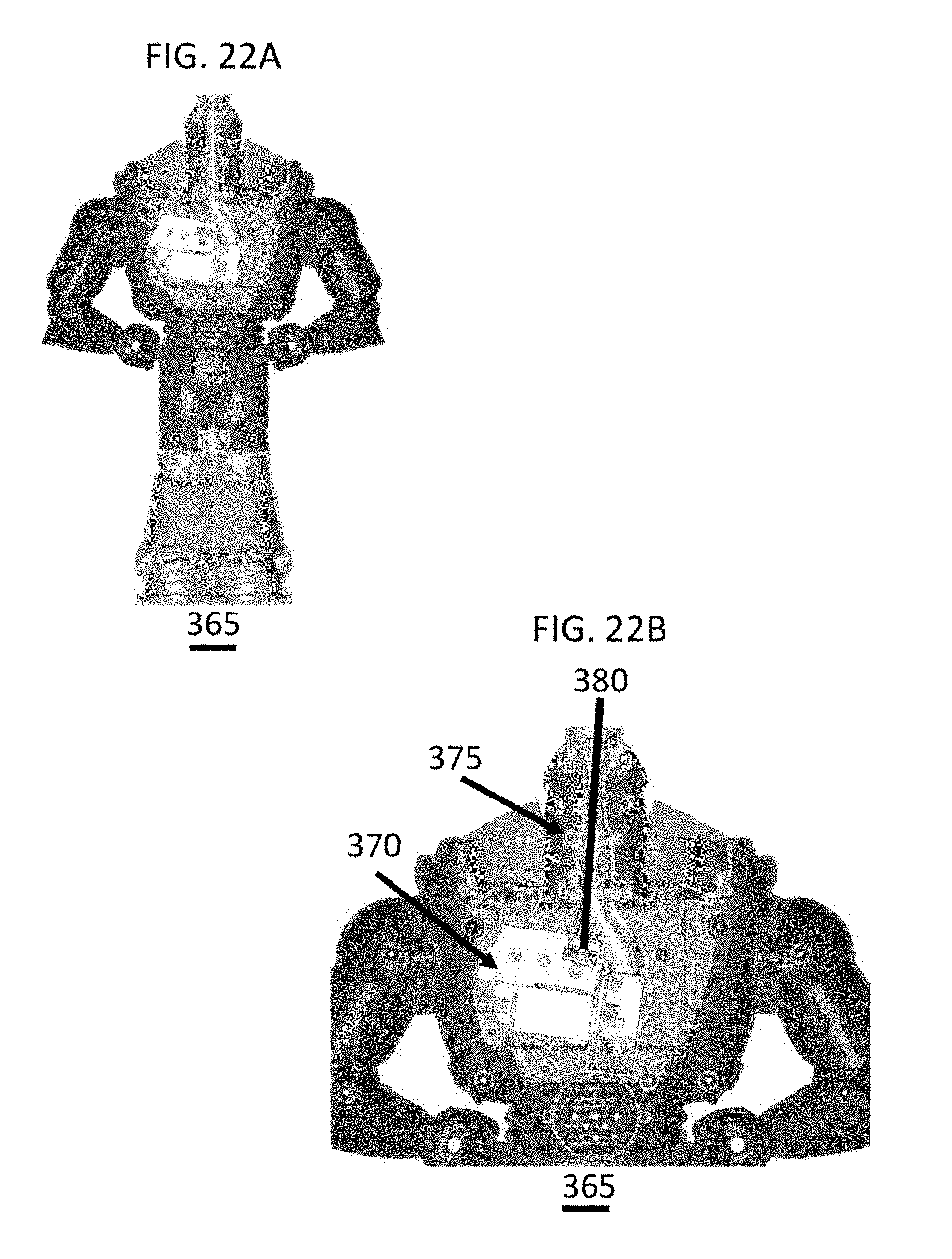
[0042] FIG. 22A-B illustrate an embodiment of a bubble chimney extender in a toy. FIG. 22A illustrates a toy with a bubble chimney extender; FIG. 22B illustrates an enlarged view of the bubble chimney extender.
[0043] FIG. 23A-B illustrate views of an embodiment of engine 3. FIG. 23A illustrates a first view of engine 3; FIG. 23B illustrates a second view of engine 3.
[0044] FIG. 24 illustrates an embodiment of engine 3.
[0045] FIG. 25 illustrates an embodiment of engine 3.
DESCRIPTION OF DRAWINGS
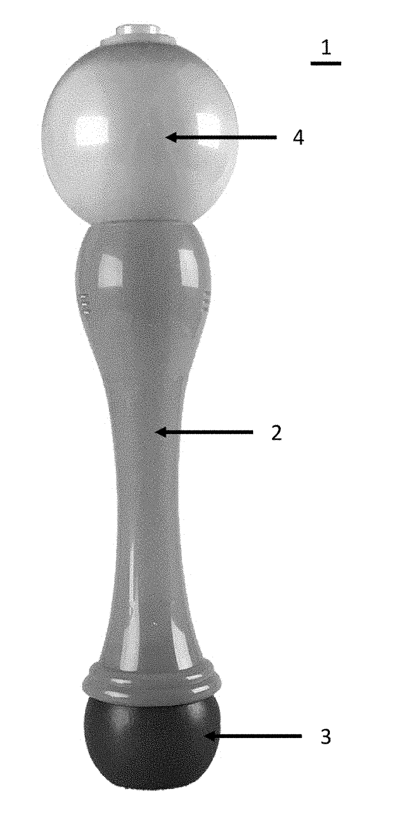
[0046] FIG. 1 depicts a front view of the present invention, which is a bubble producing toy or wand that integrates lighting effects and sound and the production of bubbles. Shown in FIG. 1 is the vertical mermaid bubble wand 1, which consists of the globe 4 (which is illuminated from within and from where the bubbles emanate), the handle/housing 2, and a removeably attachable reservoir 3.
[0047] FIG. 2 depicts a top view of the present invention, showing the top of the globe 4 and the exit orifice from which bubbles emit 10. Within the center within the exit orifice from which bubbles emit 10 is the inner bubble dispensing ring 11 and the rotating film applicator 12.
[0048] The rotating film applicator 12 moves in a circular motion and spreads a bubble film around the inner bubble dispensing ring 11. A motor-driven fan 22 (not shown) within causes air to blow through the center of the inner bubble dispensing ring 11, thus forming bubbles which emanate outward from the globe 4. External LED 20 illuminates these bubbles as they leave the vertical mermaid bubble wand 1. The top outer ring on globe 7 is more a cosmetic and ornamental feature on the surface of the globe 4, which in this embodiment is a two-piece assembly held together with screws within the globe securing screw holes 9. The present invention incorporates specially designed synchronization of lights and sound with bubble production, and a new and improved rotating film applicator 12 engineered to reduce excess bubble solution on the inner bubble dispensing ring 11.
[0049] FIG. 3 is a close-up back view of the exterior of the vertical mermaid bubble wand 1, showing the audio grill 13 located on the handle/housing 2.
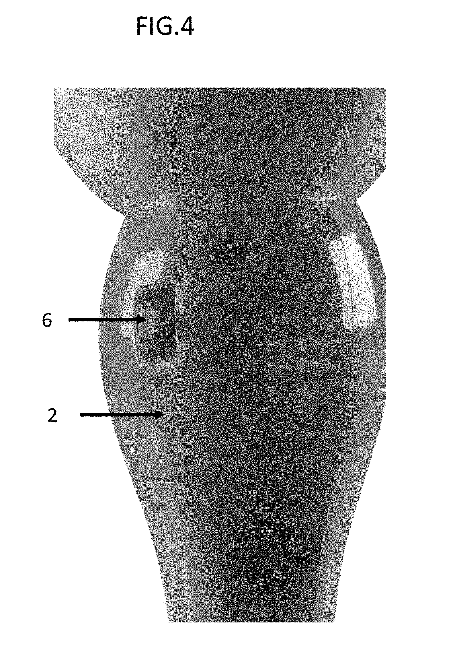
[0050] FIG. 4 is a close-up front view of the exterior of the vertical mermaid bubble wand 1, showing the switch 6 located on the handle/housing 2.
[0051] FIG. 5 is a close-up view considering the interior cavity at the bottom of the invention, with the remove ably-attachable reservoir 3 removed. Shown is the handle/housing 2, reservoir to pump input 17, and the return line drain 14. Also shown is the seal cap 15, which prevents leakage when the removeably-attachable reservoir 3 is attached and screwed within the handle/housing 2, thus allowing the reservoir to pump input 17 tube and the return line drain 14 tube to enter the interior of the removeably-attachable reservoir 3.
[0052] FIG. 6 is a close-up view considering the interior cavity of the invention showing the handle/housing 2, the switch 6, the speaker 28, battery compartment 32 with negative battery terminal 29, and the globe 4.
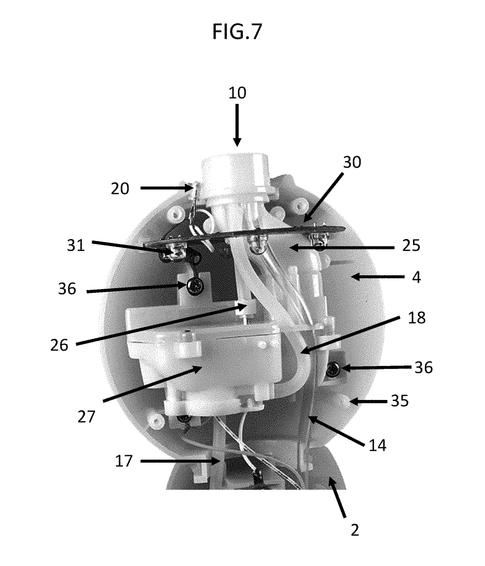
[0053] FIG. 7 is a close-up view considering the interior cavity of the invention showing the motor/pump/fan housing 27 secured within the globe 4 via motor/pump/fan housing securing screw 36. Globe 4 attaches to handle/housing 2. Contained within the motor/pump/fan housing 27 is the motor 21 (not pictured and internally located) which powers the fan 22 (not shown and internally located) and the gear reduction sub system 33 (not shown and internally located) which drives the positive displacement pump 34 (not shown and internally located) and the rotating film applicator drive shaft 26. FIG. 8 shows the fan air input 24 and the fan impeller 23. Returning to FIG. 7, the fan duct 25 carries air from the fan impeller 23 to the exit at least one orifice from. which bubbles emit 10 after air passes through the inner bubble dispensing ring 11. The pump output feed line to dispensing ring sub-assembly 18 can be seen, and this carries bubble solution from the output of the pump 34 (not shown) to the inner bubble dispensing ring 11. Also shown is return line drain 14 which carries excess bubble solution back to the removeably-attachable reservoir 3. Also shown is the circular ring PCB 30 on which are attached the globe illuminating LEDs 31, of which in this embodiment there are six pointing downward, and external LED 20 which points upward to illuminate bubbles emanating vertically from the exit orifice from which bubbles emit 10. Emanating vertically from the motor/pump/fan housing 2 is the rotating film applicator drive shaft 26 which passes through the wall of the fan duct 25, and is directly coupled to the rotating film applicator 12, thus causing the rotating film applicator 12 to rotate and spread bubble solution across the surface of the inner bubble dispensing ring 11. Also, can be seen is a screw receiving boss 35 which holds both halves of the globe 4 together when receiving a screw.
[0054] The globe illuminating LEDs 31 can be a multitude of LEDs of varying colors. In one embodiment, the invention integrates six LEDs inside the globe 4, and these are programmed to synchronize with the music or sound emitting from speaker 28 and the audio grill 13 External LED 20 can be more than one LED in other embodiments and can also be a multitude of colors including but not limited to one or more multi-colored LEDs.
[0055] The three-position activation switch 6 in this embodiment has three functions and positions: [0056] 1) UP: lights and sound on, with bubbles, [0057] 2) MIDDLE: off [0058] 3) DOWN: lights and sound on, and no bubbles.
[0059] In other embodiments of the invention there can be other combinations of features. The battery compartment 32 on the invention is a separate internal container with external contacts, wherein removably-insertable batteries (not shown), which are accessible through the battery compartment door 5 on the side of the invention's handle/housing 2 can be removably-attached by use of an attaching device, fastener, or screw.
[0060] FIGS. 9A-C depicts the Bubble Wand battery pack with an anti-reverse polarity feature 110. If one or more batteries are inserted backwards (called reverse polarity), the batteries can heat up, leak, cause fire or even explode. The anti-reverse polarity feature makes it so that it is impossible for the batteries to be put in backwards and still close the electrical circuit. The anti-reverse polarity feature consists of two white small plastic sliders 110. The bump 115 on the positive terminal of the battery can reach past the plastic slider and complete the circuit. However, the plate on the negative terminal 120, cannot reach past the plastic slider, so if one or more of the three batteries is/are flipped in the wand, the circuit cannot be closed.
[0061] FIG. 10 depicts the Bubble Wand with a more isolated battery pack whereby the battery pack is more isolated from the rest of the toy. The battery compartment is inside the main body of the wand 125 but has its own housing that isolates it from the main body of the wand 135. This better protects the batteries from dirt and liquids from external sources. It also protects the batteries from possible contamination from internal bubble solution. This battery pack limits access to the inside of the toy via a battery door. The battery door accesses the main body compartment of the wand 130 and the battery door accesses the battery compartment only, not the main body compartment 140 & 145.
[0062] Next are comparisons of bubble engines 1, 2 and 3, whereby in FIG. 11, engine 1 (170) was the inventions first bubble engine, engine 2 is an improvement of engine 1 by decreasing the profile width and using clear transparent plastic 175 instead of white 170. The chimney on engine 2 was rotated 115 to slim the profile. Engine 2 has one more bevel gear 165 in its gear train. Engine 3 is a modified version of engine 2 and made to fit inside toys that engine 2 could not and is able to attach a chimney extender for tall/slender toy parts.
[0063] FIG. 12A shows that engine 2's housing was changed to clear plastic 180 in order to reduce the shadows 185 that the white plastic engine produces when the LEDs are turned on shown in the wand 190 (illustrated in FIG. 12B).
[0064] FIG. 13A shows engine 1 and how the bubble chimney was rotated. As mentioned above, the bubble chimney was rotated to slim the profile of engine 2, illustrated in FIG. 13B. This provides two benefits: 1. Engine 2 can fit into tighter spaces in the final product (i.e., bubble wands, etc.) and so there is more freedom in shapes and sizes that can be designed. 2. The slimmer profile further reduces the shadows that it casts in the LED light.
[0065] FIG. 14 shows that because the bubble chimney was rotated, the wiper drive shaft had to be rotated with it. So a bevel gear 215 was added to the end so it could still connect with the gear train.
[0066] FIGS. 15A-B & 16A-B shows the old Engine 1 (230) with 4 gears and the newer engine 2 (225) with 5 gears and the gear train for each engine. The fifth gear was added to change the orientation of the wiper shaft. FIGS. 16A-B shows the difference between the old engine's gear layout and the new engine's gear layout.
[0067] FIG. 17 depicts benefits of bubble engine 3. Of which engine 3 is/was 1. Made to fit inside toys that engine 2 could not, 2. an improved bubble solution pump, 3. an improved wiper axel placement, and 4. able to attach a bubble chimney extender. In FIG. 17, where engine 2 is 270 and engine 3 is 275, the changing of the direction of the chimney makes the engine more compact 265.
[0068] FIGS. 18A-B shows examples of engines 2 (FIG. 18A) and 3 (FIG. 18B) in toys. The picture on the left has engine 2 in it and the picture on the right has engine 3 in it.
[0069] FIGS. 19A-B shows the improved bubble solution pump of engine 3 with a pump cap 290, a plastic tube connector 300 that prevents the rubber hose from being pushed out of the peristaltic pump, one hose 295 fitting over one side of the connector and a second hose that fits over the other side of the connector.
[0070] FIGS. 20A-B shows yet another improvement to the bubble solution pump and how the hose in engine 2 (315 of FIG. 20A) can be pushed out and cannot be pushed out in engine 3 (320 of FIG. 20B) because of the change in the hose paths as shown for engine 2 (315) path 310 versus the hose path for engine 3 (320) as shown in paths 1 (330) and 2 (325).
[0071] FIGS. 21A-B shows the improved wiper axel placement. In engine 2 (355 of FIG. 21A), because of the path of the wiper axel (335), the axel goes out and back into the engine housing, leaving opportunity for dirt or solution to enter the engine 340, where in engine 3 (360 of FIG. 21B), the path of the wiper axel (345) shows the axel is completely contained in the engine housing (350).
[0072] FIGS. 22A-B shows engine 3's (370) ability to attach a bubble chimney extender. Engine 3 and chimney extender are shown here in a Buzz Lightyear toy (365). The chimney extender (375) connects to engine 3 (370) and directs air and the wiper axel to the top (380).
[0073] FIGS. 23A-B through 25 show different views of engine 3 (390 & 395)
[0074] While the drawings, and photographs depicted as the preferred embodiments of this invention include images, likenesses, logos, marks, themes, and music of Disney's Little Mermaid, this invention in no way claims any superior intellectual property rights over any of these characters and attributes which are the rightful property of Disney.
Definitions
[0075] Bubble solution is bubble solution and/or other liquid, solid, gas, or combination thereof.
[0076] Engine includes at least of a motor, gears, gear-train, pump, fan, chimney, air ducts, orifices, dispensing device.
[0077] Chimney refers to a duct, tube, or other conduit or extension thereof,
* * * * *
D00000
D00001
D00002
D00003
D00004
D00005
D00006
D00007
D00008
D00009
D00010
D00011
D00012
D00013

D00014

D00015

D00016

D00017
D00018

D00019

D00020

D00021
D00022
D00023

D00024

D00025

P00999
XML
uspto.report is an independent third-party trademark research tool that is not affiliated, endorsed, or sponsored by the United States Patent and Trademark Office (USPTO) or any other governmental organization. The information provided by uspto.report is based on publicly available data at the time of writing and is intended for informational purposes only.
While we strive to provide accurate and up-to-date information, we do not guarantee the accuracy, completeness, reliability, or suitability of the information displayed on this site. The use of this site is at your own risk. Any reliance you place on such information is therefore strictly at your own risk.
All official trademark data, including owner information, should be verified by visiting the official USPTO website at www.uspto.gov. This site is not intended to replace professional legal advice and should not be used as a substitute for consulting with a legal professional who is knowledgeable about trademark law.